Having verified the brake sensors work and with some idea of their actuation distances, installing them on Mary’s Tour Easy involved no more than:
- Remove the fairing
- Unwrap three spiral looms from All The Cables
- Wrestle the Julet connectors apart
- Plug in the new sensors
- Stick the sensors in the proper locations
- Verify proper brake operation
- Rewrap the looms
- Install the fairing
The “proper location” put the actuation point about halfway between the brake lever’s released and pulled positions. Given that the previous sensors lacked indicators, I don’t know where their actuation point might have been, other than likely too close to their released position.
A slideshow of the front brake lever positions:
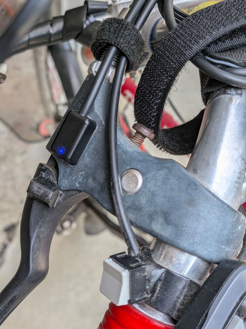

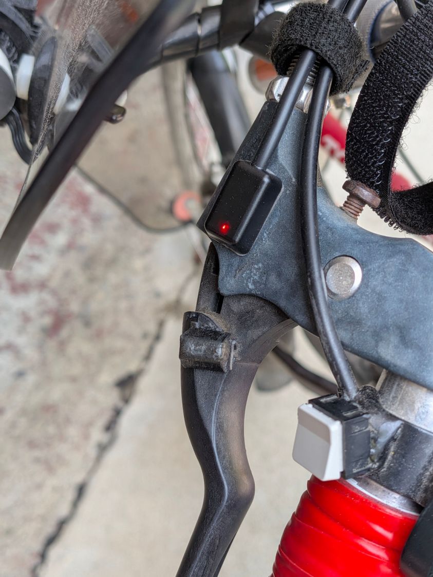
Similarly for the rear brake lever positions:
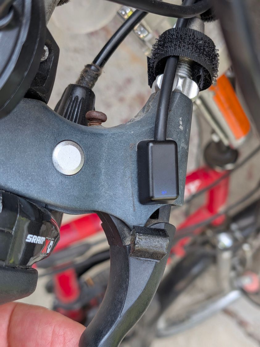
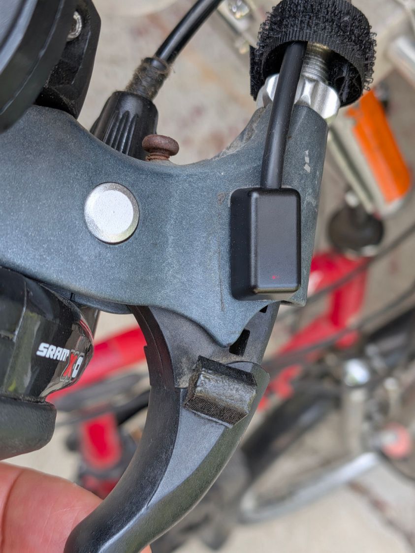
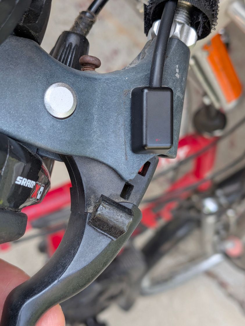
Obviously, the rear brake lever sensor has the “dim” LEDs.
There’s not much to go wrong and the first ride was uneventful, so we’ll declare victory until the sensors or magnets shift their position, despite the wraps holding their wires to the brake cables.
The magnets come from power toothbrush heads, encased in urethane adhesive in 3D printed mounts.
Stipulated: I sometimes over-do things.
However, I am absolutely not going to back down from saying the lashup shown in this screen grab from the sensor installation video is utterly and completely wrong:
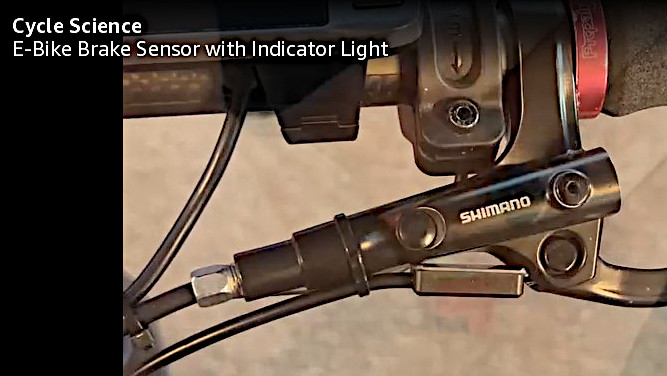
Do not get me started, you know how I am. OK?


Spam comments get trashed, so don’t bother; you’re not as clever as you think. Comment moderation may cause a delay.