Some years ago we acquired a free quartet of aluminum-frame patio chairs in need of new straps and feet. Eventually enough straps broke to force me to re-strap the things and I finally got around to replacing the badly worn OEM feet:
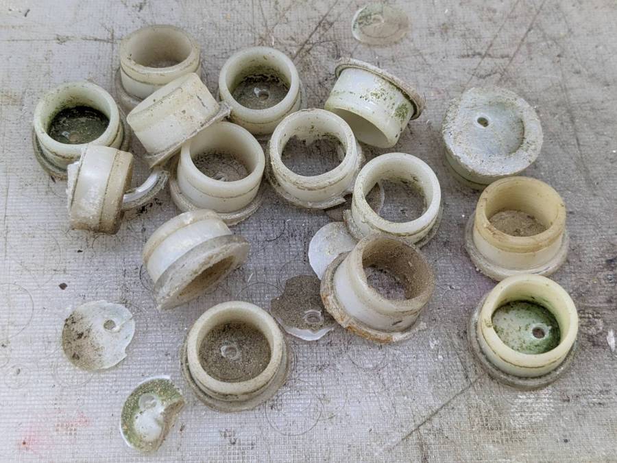
The small drilled holes let me yoink most them out with sheet-metal screw attached to a slide hammer, then apply the Designated Prydriver to the most recalcitrant / broken ones.
Some feet had worn enough to expose the aluminum tubes, but most had at least a thin layer of plastic:

Obviously, I should have stripped and repainted the frames (if that’s possible, as they’re probably powder-coated), but a man’s gotta know his limitations and this job needed to get done.
One might think patio furniture replacement feet are cheap & readily available, but no amount of keyword engineering produced search results with any degree of assured fit, so I conjured adapters for screw-in feet from the vasty digital deep:
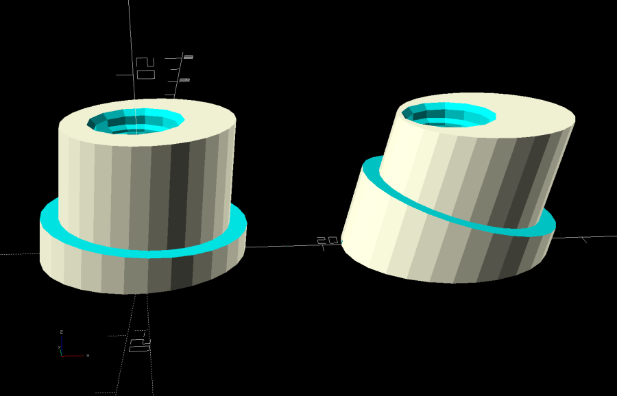
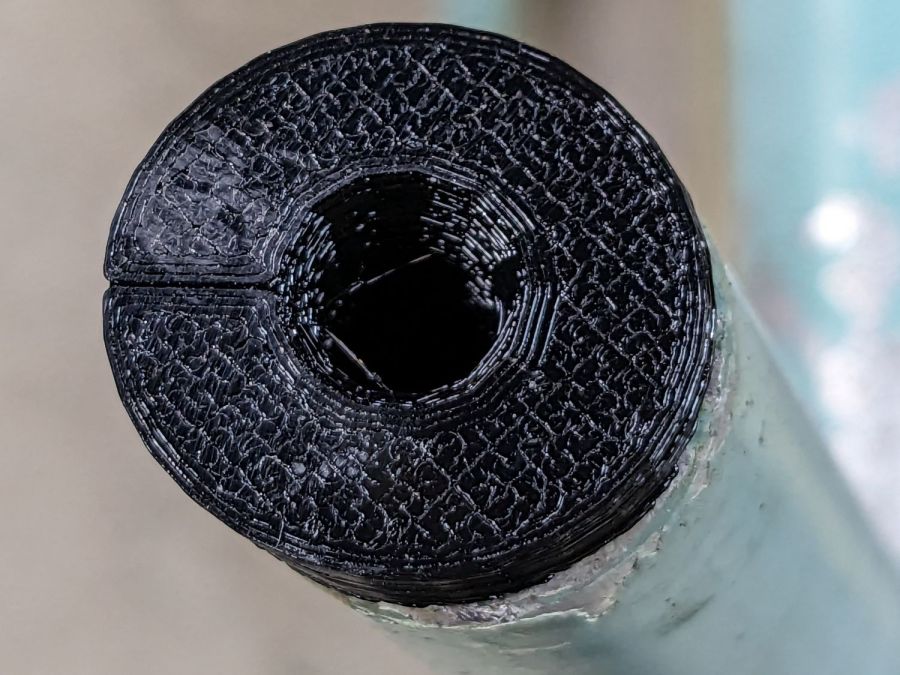
This was a long-awaited opportunity to explore the BOSL2 library and it worked wonderfully well. Each adapter is whittled from a huge hex nut with threads that perfectly fit the M8×1.25 stud, which stands vertically through the middle of the (slightly oval) bottom surface parallel to the floor.
The front tubes have a 5° angle with respect to the vertical:
And the rear tubes are 15° off:
Each adapter has an orientation notch pointing toward the front of the front leg and the rear of the rear leg:
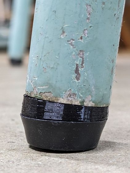
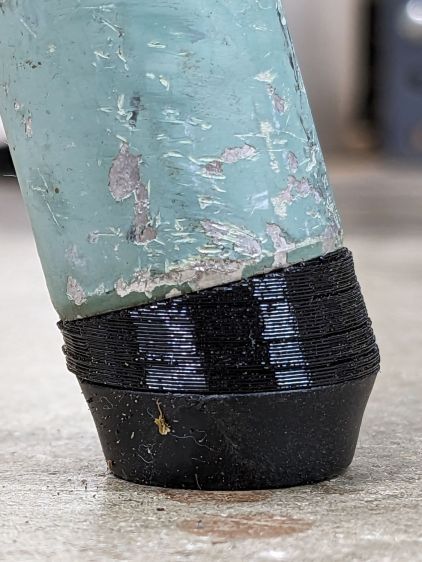
I expected to apply adhesive on the inside and outside of the adapters, but they tapped firmly into place inside the legs and the studs screwed firmly into them, so we’ll see how they survive in actual use. I expect the studs to rust after a while, but that might not be the most awful thing ever to happen.
The OpenSCAD source code as a GitHub Gist:
| // Patio chair foot adapter | |
| // Ed Nisley – KE4ZNU – 2023-06 | |
| include <BOSL2/std.scad> | |
| include <BOSL2/threading.scad> | |
| LegAngles = [5,15]; | |
| /* [Hidden] */ | |
| ThreadThick = 0.25; | |
| ThreadWidth = 0.40; | |
| HoleWindage = 0.2; | |
| Protrusion = 0.1; // make holes end cleanly | |
| function IntegerMultiple(Size,Unit) = Unit * ceil(Size / Unit); | |
| ID = 0; | |
| OD = 1; | |
| LENGTH = 2; | |
| inch = 25.4; | |
| //———————- | |
| // Dimensions | |
| LegTube = [18.8 – HoleWindage,22.5,0]; | |
| Stud = [8.0,1.25,10.0]; // M8x1.25 foot stud | |
| FlangeBase = 3.0; | |
| //———————– | |
| for (i=[0:len(LegAngles)-1]) { | |
| ang = LegAngles[i]; | |
| FlangeIncr = LegTube[OD]*tan(ang); | |
| Flange = [Stud[0],LegTube[OD],FlangeBase + FlangeIncr]; | |
| translate([i*1.5*Flange[OD],0,0]) | |
| difference() { | |
| translate([0,0,0*-FlangeIncr/2]) | |
| threaded_nut(2*Flange[OD],Stud[0],1.5*Stud[2],Stud[1], | |
| anchor=BOTTOM,bevel=false,$slop=0.2); | |
| rotate([0,ang,0]) { | |
| translate([0,0,FlangeBase + FlangeIncr/2]) | |
| tube(4*Stud[2],2*Flange[OD],LegTube[ID]/2, | |
| anchor=BOTTOM); | |
| tube(4*Stud[2],2*Flange[OD],Flange[OD]/2, | |
| anchor=CENTER); | |
| } | |
| cube([Flange[OD],ThreadWidth,2*ThreadThick],anchor=BOTTOM+RIGHT); | |
| } | |
| } |

Comments
4 responses to “Patio Chair Foot Adapters”
If the tube diameter is compatible you might have used rubber cane tips. These are available in several sizes. Example:
https://www.walmart.com/ip/Equate-3-4-Rubber-Cane-Tips-2-Count/776646650
The chair tubes are annoyingly larger than ¾ inch OD (maybe ⅞ inch would fit?) and I think those raw ends would punch through the rubber in short order. They might wear better than hard plastic against the concrete, though.
For less than half the price, I got to do some solid modeling!
With such a shape, it may be interesting to split the body with a median plane, and print two half-cylindrical parts :
Some superglue and the tube will keep them together, and overall resistance to shearing forces does not depend on layer cohesion.
Aye!
I think that chunky steel screw up the middle will distribute the stress evenly enough to let the plastic hang together, particularly because the whole thing is under compression around the perimeter. A couple of early failures will convince me otherwise, in which case I’ll try a different layout.
FWIW, our Young Engineer printed some spectacularly nice screw threads laid out horizontally, which I wouldn’t have believed possible.