The Smell of Molten Projects in the Morning

Ed Nisley's Blog: Shop notes, electronics, firmware, machinery, 3D printing, laser cuttery, and curiosities. Contents: 100% human thinking, 0% AI slop.

Month: May 2018

  • Squidwrench Electronics Workshop: Session 2

    Some ex post facto notes from the second SquidWrench Electronics Workshop. This turned out much more intense than the first session, with plenty of hands-on measurement and extemporized explanations.

    Measure voltage across and current through 4.7 kΩ 5 W resistor from 0.5 V to 30 V. Note importance of writing down what you intend to measure, voltage values, units. Plot data, find slope, calculate 1/slope.

    Introduce parallel resistors: 1/R = 1/R1 + 1/R2. Derive by adding branch currents, compute overall resistance, factor & reciprocal.

    Review metric prefixes and units!

    Introduce power equation (P = E I) and variations (P = I² R, P = E²/R)

    Measure voltage across  and current through incandescent bulb (6 V flashlight) at 0.1 through 6 V, note difference between voltage at power supply and voltage across bulb. Plot data, find slopes at 1 V and 5 V, calculate 1/slopes.

    Measure voltage across ammeter with bulb at 6 V, compute meter internal resistance, measure meter resistance. Note on ammeter resistance trimming.

    Measure voltage across and current through hulking power diode from 50 mV – 850 mV. Note large difference between power supply voltage and diode voltage above 750-ish mV. Note power supply current limit at 3 A. Plot, find slopes at 100 mV and 800 mV, calculate 1/slopes. Compare diode resistance with ammeter resistance.

    Review prefixes and units!

    The final whiteboard:

    Whiteboard - Session 2
    Whiteboard – Session 2

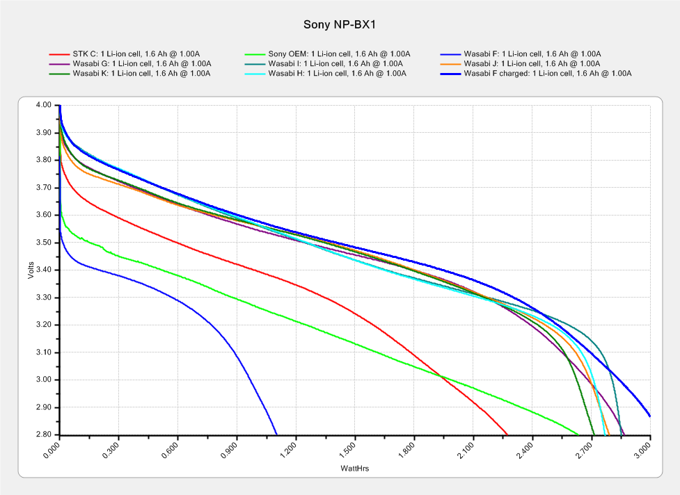
    Hand-measured data & crude plots FTW!

  • Squidwrench Electronics Workshop: Session 1

    Some ex post facto notes from the first SquidWrench Electronics Workshop, in the expectation we’ll run the series from the start in a while. I should have taken pictures of my scribbles on the whiteboard.

    Define:

    • Voltage – symbol E (Electromotive Force or some French phrase), unit V = volt
    • Current – symbol I (French “intensity” or some such), unit A = ampere
    • Resistance – symbol R (“resistance”), unit Ω (capital Greek Omega) = ohm

    Introduce Ohm’s Law & permutations, postpone calculations.

    Measure the actual voltage of assorted cells & batteries. Identify chemistry, internal wiring:

    • 1.2 = nickel-cadmium or nickel-metal-hydride
    • 1.5 = carbon-zinc or alkaline
    • 2 V = lead-acid
    • 3.0 = primary lithium
    • 3.6 – 3.7 = rechargeable lithium, several variations
    • 4.8 = 4 x 1.2 V
    • 7.2 = 6 x 1.2 V
    • 7.4 = 2 x 3.6 V
    • 9.6 = 8 x 1.2 V
    • 10.8 = 3 x 3.6 V
    • 12 = 6 x 2 V

    Measure various resistors, favoring hulking finger-friendly sandstone blocks.

    Introduce metric prefixes:

    • Engineering notation uses only multiple-of-three exponents
    • μ = micro = 10-6
    • m = milli = 10-3
    • k = kilo = 103
    • M = mega = 106

    Discuss resistor power dissipation vs. size vs. location, postpone power formula.

    Clip-lead various resistors to various batteries, measure voltage & current.

    Introduce fixed & variable power supplies, repeat resistor measurements.

    Now compute permutations of Ohm’s Law using actual data!

  • Monthly Image: Nice Doggie

    “He’s very friendly!”

    “She won’t bite!”

    That’s what all dog owners say when their dog lunges at you:

    Dog Lunge - DCRT 2017-05-13
    Dog Lunge – DCRT 2017-05-13

    We sounded our usual bike bell dings while approaching and moved as far to the left as we could. The group compressed to the right, which was unusually courteous, we said nothing, and they said nothing while their dog barked and lunged at both of us.

    Perhaps we are easily startled, but we do not regard lunging and barking as friendly or sociable gestures. Even as pedestrians, we do not want our crotches explored, our hands licked, or our chests pawed.

    AFAICT the only reason Mary didn’t get knocked over and gnawed was a good grip on a thin leash. Maybe the dog would just lick her to death, but it’s still unwanted aggression.

    From what I’ve read, dog shoulders operate as front-to-back rotating pivots, rather than all-direction ball joints. Disabling an attacking dog thus requires grabbing its front legs and spreading them as far apart as possible, which is feasible because human arms are much stronger laterally than dog legs. While the process brings one’s head entirely too close to the dog’s jaws, it apparently breaks most of the dog’s ribs, collapses its lungs, and instantly puts it out of action.

    I devoutly hope I need never test that maneuver under field conditions, as I can see serious repercussions. If it’s in Mary’s face, however, I will not err on the side of generosity.

    Protip: if your dog isn’t well-trained enough to completely ignore strangers, don’t bring it near strangers who may not be dog people.

  • Sony NP-BX1 Battery Status

    The genuine Sony NP-BX1 that came with the AS30V camera suffers from voltage depression (green trace) and no longer survives a typical ride:

    Sony NP-BX1 - 2018-04-24
    Sony NP-BX1 – 2018-04-24

    The STK C battery (red trace) is also pretty much kaput, so the two of them go into the recycle bag.

    The very short blue trace is the Wasabi F battery after a ride, showing about 1 W·h remaining of the initial charge. After a full change, the upper blue trace shows it has a capacity in the same range as the others. Our rides are about an hour long, so the camera draws somewhat less than the 1 A test current, roughly what I’d estimated from other data.

    The cluster of traces along the top show the remaining Wasabi batteries are all pretty much alike, with the older F and G batteries no worse than the newer (and unused) H I J K batteries. I’m underwhelmed by the overall performance of the latter four, as I’d expect them to be better than their well-used predecessors.

    I’m still mulling an external 18650 cell grafted into a NP-BX1 carcass, but it’s stalled behind some other projects.

  • Tour Easy: SRAM X.9 Grip Shift Replacement

    The rear shifter on my Tour Easy stopped working when we were most of the way to the grocery store, due to what turned out to be due to a broken cable. I managed to yank the frayed end out of the shifter, pulled the derailleur into a middling gear, and belayed the cable into a deadly cactus:

    SRAM X.9 Rear Shifter - frayed cable
    SRAM X.9 Rear Shifter – frayed cable

    A three-speed recumbent got me home again, albeit with spin-it-out high gear and a low gear barely sufficient for trailer hauling.

    Attempting to remove the frayed cable from the SRAM X.9 grip shifter didn’t go well at all:

    SRAM X.9 Rear Shifter - cable tangle
    SRAM X.9 Rear Shifter – cable tangle

    I managed to extract the lead pellet, but, while it may be possible to extract the remaining tangle, even pulling on individual wires wasn’t productive.

    AFAICT, the shifter came as original equipment on the bike, so it’s been in constant use for the last 17-ish years. The nice soft grip material (and the cover over the cable port) turned into gummy sludge under the cheerful silicone tape I applied some years ago, so I sliced the old grip and pulled it off:

    SRAM X.9 Rear Shifter - gummified grip
    SRAM X.9 Rear Shifter – gummified grip

    Popping a new-old-stock X.9 shifter from the Big Box o’ Bike Parts and installing it proceeded without problems. This being the rear shifter, I had to remove the shiny OEM cable and replace it with a PTFE-coated tandem-length rear cable, but that’s normal for a long wheelbase recumbent.

    For the record, both black shift indicator tabs still show no signs of failing after half a year, so a bent piece of polypropylene sheet looks like a win.

  • Relic of the Empire: Pay Phone Mount

    Spotted at the NSQG World of Quilts show in the WCSU O’Neill Center:

    Payphone mounting plate
    Payphone mounting plate

    I’m mildly surprised the (apparently recent) wall reupholstering didn’t cover it up. I’m certain many students don’t recognize it.

    The FCC says the US is down to 100 k pay phones from a peak of over two million; they don’t tally the number of bare wall mount plates, though.


  • MPCNC: Tweaked GRBL Config

    These GRBL configuration constants seem to work well with the DW660 router in the MPCNC gantry:

    $$
    $0=10
    $1=255
    $2=0
    $3=2
    $4=0
    $5=0
    $6=0
    $10=1
    $11=0.010
    $12=0.002
    $13=0
    $20=1
    $21=1
    $22=1
    $23=0
    $24=500.000
    $25=2500.000
    $26=250
    $27=3.000
    $30=30000
    $31=0
    $32=0
    $100=100.000
    $101=100.000
    $102=400.000
    $110=8000.000
    $111=8000.000
    $112=3000.000
    $120=2000.000
    $121=2000.000
    $122=2000.000
    $130=635.000
    $131=465.000
    $132=103.000
    —–
    $n
    $N0=F150
    $N1=G10L2P1X-633Y-463Z-3
    —–
    $#
    [G54:-633.000,-463.000,-3.000]
    [G55:0.000,0.000,0.000]
    [G56:0.000,0.000,0.000]
    [G57:0.000,0.000,0.000]
    [G58:0.000,0.000,0.000]
    [G59:0.000,0.000,0.000]
    [G28:-418.670,-282.016,-3.000]
    [G30:-628.000,-3.000,-3.000]
    [G92:0.000,0.000,0.000]
    [TLO:0.000]
    [PRB:0.000,0.000,0.000:0]
    view raw MPCNC-GRBL.cfg hosted with ❤ by GitHub

    The overall XY travel is slightly smaller than the initial configuration, because the router sticks out further than the penholder I’d been using. Increasing the $27 Homing Pulloff distance to 3 mm leaves a comfortable space beyond the limit switches after homing to the positive end:

    MPCNC - X-axis endstop - home
    MPCNC – X-axis endstop – home

    Adjusting the $13[01] XY travel distances and switch positions on the other end of the rail leaves a similar comfort zone at the negative end:

    MPCNC - X-axis endstop - X min
    MPCNC – X-axis endstop – X min

    Both switches now live on the rear X-axis rail and appear as seen from behind the bench; they just look backwards. The Y-axis switches are on the left rail and look exactly the same.

    The XY travel works out to 630 × 460 mm = 24.8 × 18.1 inch, which is Good Enough.

    Some fiddling with the Z axis limit switch tape mask produces a nice round 100 mm = 3.9 inch vertical travel. The Z-axis rails just barely clear the table at the lower limit and just barely stay in the bottom bearings at the upper limit, so it’s a near thing. In practical terms, the rails or the tool will smash into the workpiece sitting atop the table before the limit switch trips.

    Setting both $20=1 Soft Limits and $21=1 Hard Limits may be excessive, but I vastly prefer having the firmware detect out-of-range moves and the hardware forcibly shut down if the firmware loses track of its position, rather than letting it grind away until I can slap the BRS. The steppers aren’t powerful enough to damage anything, of course, so it’s a matter of principle.

    The $N0=F150 sets the initial speed, as the default F0 seems to (sometimes) confuse bCNC’s auto-level grid probing.

    The $N1=G10L2P1X-633Y-463Z-3 sets the default G54 coordinate origin to the front-left corner, with Z=0 at the home position up top, so as to prevent surprises. I expect to use G55 for most work holder touchoffs, although we’ll see how that plays out.

    The G28 and G30 settings depend on the tool change location and the Z-axis probe location, so they’re still not cast in concrete.