The Smell of Molten Projects in the Morning

Ed Nisley's Blog: Shop notes, electronics, firmware, machinery, 3D printing, laser cuttery, and curiosities. Contents: 100% human thinking, 0% AI slop.

Month: January 2018

  • Kenmore Electric Dryer: Power Resistor Replacement

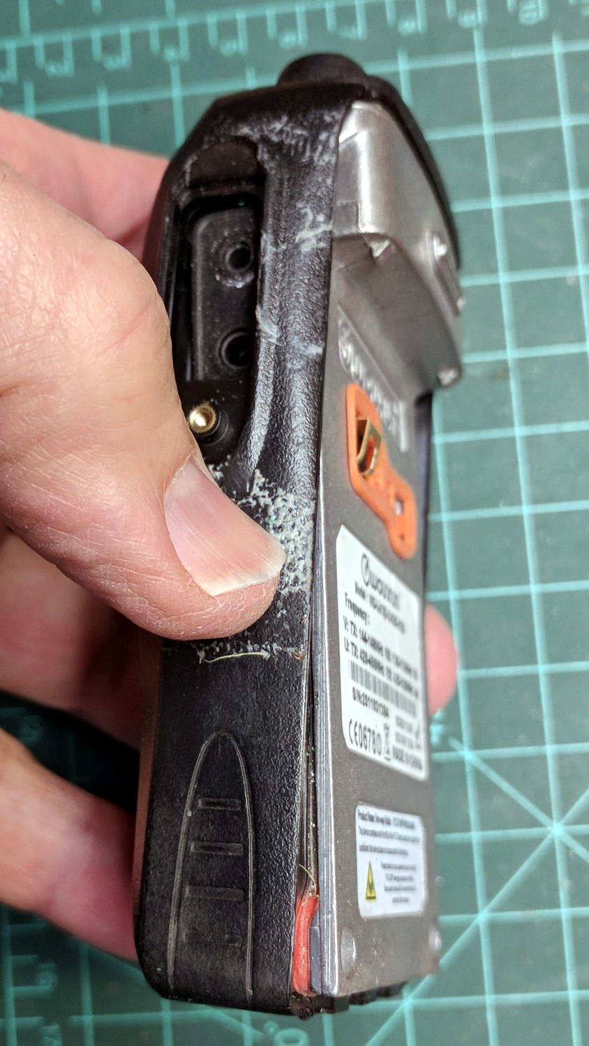
    Our long-suffering and much-repaired Kenmore clothes dryer didn’t shut off, with the heat on and the timer failing to advance from whatever position we set it to; the clothes were plenty dry and scorching hot. I tried “timed air dry” to eliminate the heater from the problem and found the timer still didn’t advance.

    Referring to the wiring diagram may be of some help:

    Kenmore clothes dryer 110.96282100 - wiring diagram
    Kenmore clothes dryer 110.96282100 – wiring diagram

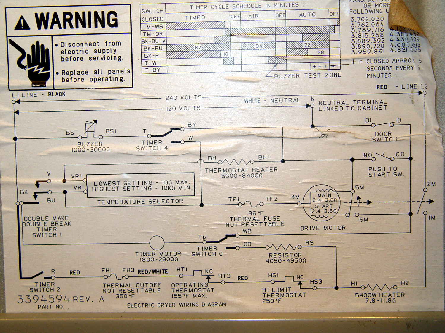
    The timer motor is in the next-to-bottom ladder rung. Its BK terminal on the left connects to one side of the 240 VAC supply and the switch just to its right connects terminal TM to either the neutral AC line (thus unbalancing the 240 VAC line by a smidge) or to through a 4-ish kΩ resistor and the heater element (essentially zero, on this scale) to the other hot line; the resistor thus dropping 120-ish VAC.

    The various switches around the timer collect nearly all the wiring in the dryer:

    Kenmore dryer - timer wiring
    Kenmore dryer – timer wiring

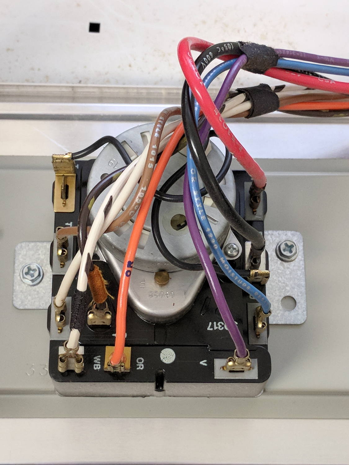
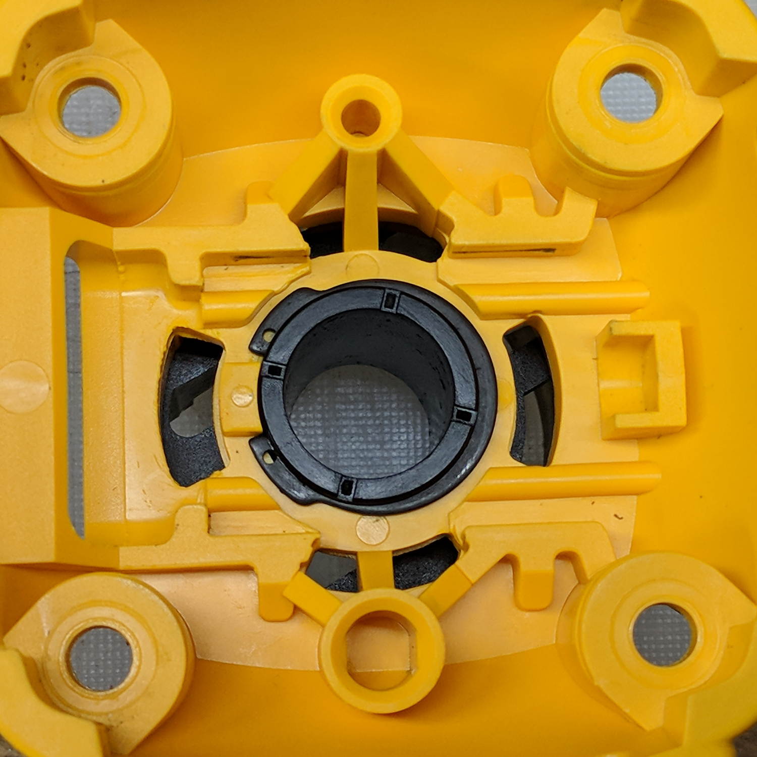
    A closer look at the back, minus all the wiring:

    Kenmore dryer - timer backplate
    Kenmore dryer – timer backplate

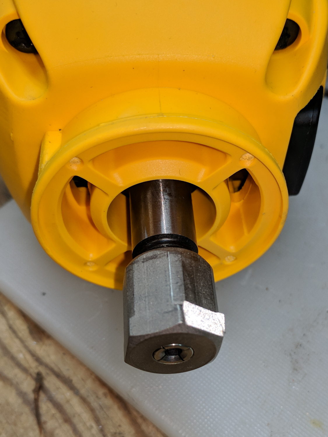
    The motor comes off easily enough, revealing the fact that it’s not just an ordinary (i.e., cheap & readily available) timer motor:

    Kenmore dryer - timer motor pinions
    Kenmore dryer – timer motor pinions

    Hotwiring the motor through a widowmaker zip cord showed it worked just fine. For reference, the upper pinion rotates at about 45 sec/rev, the lower pinion takes maybe 1 hr/rev, both counterclockwise.

    Reassembling and hotwiring the complete timer showed it worked just fine, too.

    Poring over the wiring diagram suggested the power resistor might be open and, indeed, it was:

    Kenmore dryer - power resistor failure
    Kenmore dryer – power resistor failure

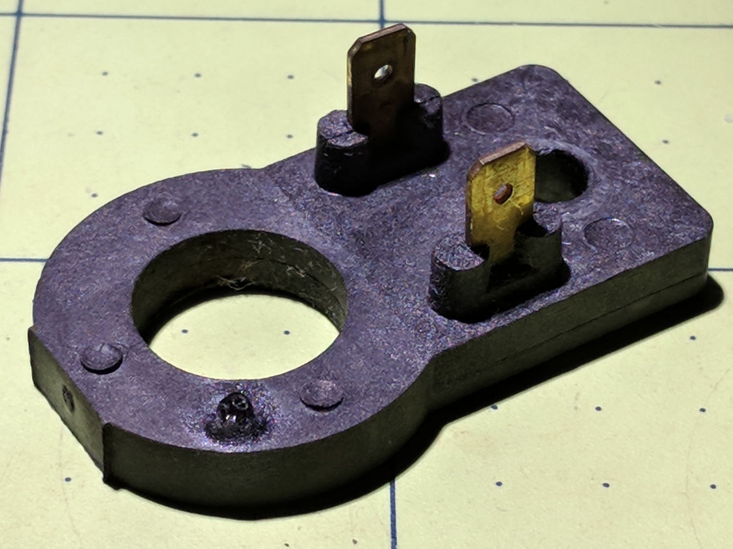
    The raised zit near the front shouldn’t be there:

    Kenmore dryer - power resistor failure - detail
    Kenmore dryer – power resistor failure – detail

    Apparently, the resistive element broke at that spot, burned through the thermoset plastic case, and failed safe.

    Introducing it to Mr Disk Sander revealed a cavity below the zit, surrounded by the remains of the resistive element:

    Kenmore dryer - power resistor - cut open
    Kenmore dryer – power resistor – cut open

    You can get a replacement resistor from the usual suspects for prices between $20 and $40, plus or minus shipping, but their pictures look a lot like an ordinary power resistor inside a length of heatshrink tubing, rather than the molded OEM part. I don’t put much stock in reviews & comments, although they seemed to suggest you get, indeed, an ordinary power resistor.

    I didn’t have a 4.7 kΩ power resistor in my (diminished) collection, so I soldered a giant 1.5 kΩ cylindrical resistor in series with a small 3.5 kΩ sandbox, wrapped them up, and tucked them under the front panel’s ground wire:

    Kenmore dryer - expedient power resistor
    Kenmore dryer – expedient power resistor

    A small box of resistors should arrive in the next month and I’ll re-do the repair with a bit more attention to permanency.

  • Measuring Spoon Drainer

    We just scrapped out the old dish drainer, only to find the gadget bin on the new drainer let the measuring spoons fall over and lie along its bottom. After a week of fishing them out from under paring knives, cheese slicers, and suchlike, I gimmicked up a holder:

    Measuring Spoon Drainer - installed
    Measuring Spoon Drainer – installed

    One might suggest natural PETG, rather than orange, thereby displaying a shocking ignorance of the MVP concept. We’ll run with orange for the shakedown trials, then build-measure-learn, iterate, and, for all I know, we may even pivot.

    A bottom-up view of the solid model shows the trench accommodating the bin lip:

    Measuring Spoon Drainer - Slic3r preview
    Measuring Spoon Drainer – Slic3r preview

    The OpenSCAD source code as a GitHub Gist:

    // Measuring spoon drainer
    // Ed Nisley KE4ZNU – 2018-01-13
    /* [Extrusion] */
    ThreadThick = 0.25; // [0.20, 0.25]
    ThreadWidth = 0.40; // [0.40]
    /* [Hidden] */
    Protrusion = 0.1; // [0.01, 0.1]
    HoleWindage = 0.2;
    function IntegerMultiple(Size,Unit) = Unit * ceil(Size / Unit);
    ID = 0;
    OD = 1;
    LENGTH = 2;
    //- Adjust hole diameter to make the size come out right
    module PolyCyl(Dia,Height,ForceSides=0) { // based on nophead's polyholes
    Sides = (ForceSides != 0) ? ForceSides : (ceil(Dia) + 2);
    FixDia = Dia / cos(180/Sides);
    cylinder(r=(FixDia + HoleWindage)/2,h=Height,$fn=Sides);
    }
    /* [Spoon] */
    SpoonOD = IntegerMultiple(3.3,2);
    SpoonWidth = IntegerMultiple(16.5,2.0);
    SpoonOC = 30.0;
    /* [Drainer] */
    Drainer = [52.0,59.5,100.0]; // overall drainer cup
    DrainerRimWidth = (Drainer[1] – Drainer[0])/2;
    DrainerRimHeight = 2.5;
    DrainerExtent = 15.0;
    /* [Hidden] */
    WallThick = 2.0; // basic wall & floor thickness
    PlateThick = WallThick + 2*DrainerRimHeight;
    NumSides = 8*4;
    //—–
    // Define shapes
    module CoverPlate() {
    OD = Drainer[OD] + 2*WallThick;
    difference() {
    cylinder(d=OD,h=PlateThick,$fn=NumSides);
    for (j=[-1,1])
    translate([-(OD/2 – Protrusion),j*(Drainer[ID]/2 + DrainerRimWidth/2),WallThick + DrainerRimHeight + Protrusion/2])
    cube([OD,DrainerRimWidth,2*DrainerRimHeight + Protrusion],center=true);
    translate([0,0,WallThick + PlateThick/2])
    rotate(-90)
    rotate_extrude(angle=180,$fn=NumSides)
    translate([Drainer[ID]/2 + DrainerRimWidth/2,0])
    square([DrainerRimWidth,PlateThick],center=true);
    translate([-(OD/2 + DrainerExtent),0,PlateThick/2])
    cube([OD,OD,PlateThick + 2*Protrusion],center=true);
    }
    }
    //—–
    // Build it
    difference() {
    CoverPlate();
    for (j=[-1,1])
    translate([0,j*(SpoonOC/2),-Protrusion])
    linear_extrude(height=PlateThick + 2*Protrusion)
    hull()
    for (i=[-1,1])
    translate([i*(SpoonWidth – SpoonOD)/2,0])
    circle(d=SpoonOD,$fn=8);
    }

    The original doodle has useful dimensions, along with the usual over-elaborate features sacrificed in order to get it made:

    Measuring spoon drainer - doodles
    Measuring spoon drainer – doodles
  • MPCNC: DeWalt DW660 Collet Grip Removal

    The MPCNC uses a DW660 Cutout tool as a low-cost spindle for tools with 1/8 and 1/4 inch shanks. It features a tool-free “collet grip” to twist the collet nut against the shaft lock, which is convenient for a hand tool and not so much for a CNC spindle: I find it difficult to get two hands into the MPCNC setup with the proper orientation to push-and-hold two locking buttons, while applying enough torque to twist the collet nut:

    DW660 - collet grip
    DW660 – collet grip

    Fortunately, it’s easy enough to remove the collet grip. Remove the collet nut, unscrew the four screws holding the yellow snout in place, then pull the snout straight off to reveal the spindle lock plate:

    DW660 - nose cap interior
    DW660 – nose cap interior

    Capture the spring, slide the spindle lock plate out to expose the snap ring (a.k.a. Jesus clip) holding the collet grip in place:

    DW660 - collet grip snap ring
    DW660 – collet grip snap ring

    Remove the snap ring, make the appropriate remark, pull the collet grip out of the snout, reassemble the snout in its One Correct Orientation, and you’re done:

    DW660 - collet grip removed
    DW660 – collet grip removed

    The retroreflective tape snippet let my laser tachometer report a top speed over 29 k rpm, pretty close to the advertised 30 k rpm.

    If one were fussy, one would 3D print a thing to cover the snout’s open end:

    DW660 - snout cover
    DW660 – snout cover

    The original snap ring holds it in place and the fancy pattern comes from octogram spiral infill on the bottom.

    The collet nut fits either a 5/8 inch or 16 mm wrench, both of which stick out to the side far enough for a convenient hold while pressing the shaft lock button.


  • Egg Size Distribution

    We got several cartons of “medium” brown eggs with what seemed like an unusually wide size distribution, so I picked out and weighed an assortment for future reference:

    Brown egg size distribution
    Brown egg size distribution

    Of course, there’s an egg size specification. Actually, there are many egg size specifications.

    We occasionally get huge eggs, tiny eggs, eggs with two yolks, no yolks, or blood-spotted yolks, all of which turn out to be no big deal. I admit to not previously encountering the term “fart egg”, however …

  • Brita Smart Pitcher Timer Innards

    After far too many repairs, we bought a new Brita pitcher with slightly different, although apparently equally crappy, hinge pins, whereupon I bandsawed the long-failed “smart” filter timer out of the old pitcher’s lid:

    Brita pitcher timer - contents
    Brita pitcher timer – contents

    The gray rectangle is the LCD panel showing how long since you last replaced the filter. It died some years ago and, indeed, the CR1616 battery was down to 2.8 V.

    However, I think the real failure happened when the black square of conductive foam slipped off the switch contacts under the Reset pushbutton’s stud and went walkabout inside the timer:

    Brita pitcher timer - opened
    Brita pitcher timer – opened

    That’s where I found it after sawing the casing open. I think the adhesive side should be stuck to the stud, but we’ll never know.

    The new pitcher includes a different indicator with green LED status blinkies for “Standard” (40 gallon) and “Longlast” (120 gallon) filter cartridges and a red blinkie for “Expired”:

    Brita pitcher - Filter Life counter
    Brita pitcher – Filter Life counter

    Yeah, purple. For some unknown reason, it cost 10% less than the other colors and we’re not fussy.

    This one measures filter use by water volume, not elapsed time, counting the number of pitcher refills by noticing when you open the flip-top lid; the corresponding volume depends on your ability to see a nearly invisible line molded into the lid. Unsurprisingly, Longlast filters cost only slightly less than three times standard ones, so they’re not a compelling value proposition.

  • Low Budget Bench Supply: Digital Version

    This one costs slightly more than the analog tattoo power supply:

    Tattoo Digital Power Supply - front panel
    Tattoo Digital Power Supply – front panel

    The gold lion really spiffs up the Electronics Workbench!

    Somewhat to my surprise, the circuit uses a switching power supply based on a Reactor Micro RM6302 controller that can produce about an amp at voltages up to about 14 V:

    Tattoo Digital Power Supply - internal view
    Tattoo Digital Power Supply – internal view

    CAUTION: Everything on the input side of the transformer runs at line potential. I have my doubts about isolation, particularly under fault conditions.

    The trimpot on the PCB seems to adjust the output voltage, although it’s not clear what’s going on.

    The three wire AC line cord has a standard IEC entry block on the rear panel, albeit with the ground terminal not connected to anything inside the plastic case. It arrived with the hot wire soldered to a tiny fuse on the PCB and the neutral wire (red!) to the back-panel switch. There being no practical way to put the fuse before the switch, I rewired the hot side to the switch before the fuse and the unswitched neutral to the PCB; that’s as good as it’ll get.

    I also flipped the AC switch to put the ON position at the top. Sheesh.

    The two 1/4 inch jacks on the front panel are wired in series, so it didn’t matter which one got the tattoo needler or the foot switch:

    Tattoo Digital Power Supply - jacks in series
    Tattoo Digital Power Supply – jacks in series

    I rewired the sockets in parallel to eliminate the need for a shorting plug, although I cannot imagine any need for two outputs.

    The knob seemed unusually sloppy, which turned out to be due to a broken threaded sleeve around the pot shaft that prevented the crudely made nut from seating tightly:

    Tattoo Digital Power Supply - broken pot threads
    Tattoo Digital Power Supply – broken pot threads

    Given that the builders stuck everything else to the front panel with hot-melt glue, I followed suit:

    Tattoo Digital Power Supply - glued pot threads
    Tattoo Digital Power Supply – glued pot threads

    Which actually held it in place reasonably well, despite the hideous appearance. The knob covers the blob, so It Doesn’t Matter.

    The output range extends from about 1.2 V to just over 14 V at about an amp, but the knob seems erratic and the digital meter has only a casual relationship to the actual output voltage.

    I think if you regard this one as a parts kit, reverse-engineer the schematic (which surely descends directly from the RM6302 datasheet), and rebuild the electronics, it might work better.

    Bottom line: The analog version seems to be better as a low-budget power supply, not least because it has a metal case and an actual power transformer for galvanic isolation.

  • Wouxun KG-UV3D: Another Failure

    Once is happenstance, twice is coincidence:

    Wouxun KG-UV3D - failure
    Wouxun KG-UV3D – failure

    Three times is enemy action, but we’re not there yet. I was willing to believe something I’d done had killed both of the radios, even though it seemed unlikely for them to last five years and fail almost simultaneously.

    So I dismantled this one to see what’s inside. Pull off both knobs, remove the two screws at the bottom of the battery compartment, pry gently with a small screwdriver, and the whole PCB pulls out:

    Wouxun KG-UV3D - disassembly
    Wouxun KG-UV3D – disassembly

    A bit more prying separates the big pieces:

    Wouxun KG-UV3D - interior
    Wouxun KG-UV3D – interior

    Looking closely at the main PCB showed some problems I definitely didn’t cause:

    Wouxun KG-UV3D - PCB overview
    Wouxun KG-UV3D – PCB overview

    Although it’s been riding around on my bike, the white blotches on the PCB came from inadequate flux removal after hand soldering.

    A collection of images taken through the microscope reveals the problems:

    This slideshow requires JavaScript.

    I swabbed off the crud with denatured alcohol to no avail. The bottom side of the PCB has even more components and, I’m sure, even more crud, but I didn’t bother removing all the screws required to expose it, nor did I dismantle the other failed HT.

    I doubt Wouxun’s QC improved over the last few years, which means the two replacement KG-UV3D radios I just bought are already on their last legs, despite my paying top dollar to the same reputable source that sold me the first pair.

    We’ll be ready for new radios on new bikes by the time these fail.