The Smell of Molten Projects in the Morning

Ed Nisley's Blog: Shop notes, electronics, firmware, machinery, 3D printing, laser cuttery, and curiosities. Contents: 100% human thinking, 0% AI slop.

Month: February 2017

  • Bandsaw Worklight: LED Cable Clips

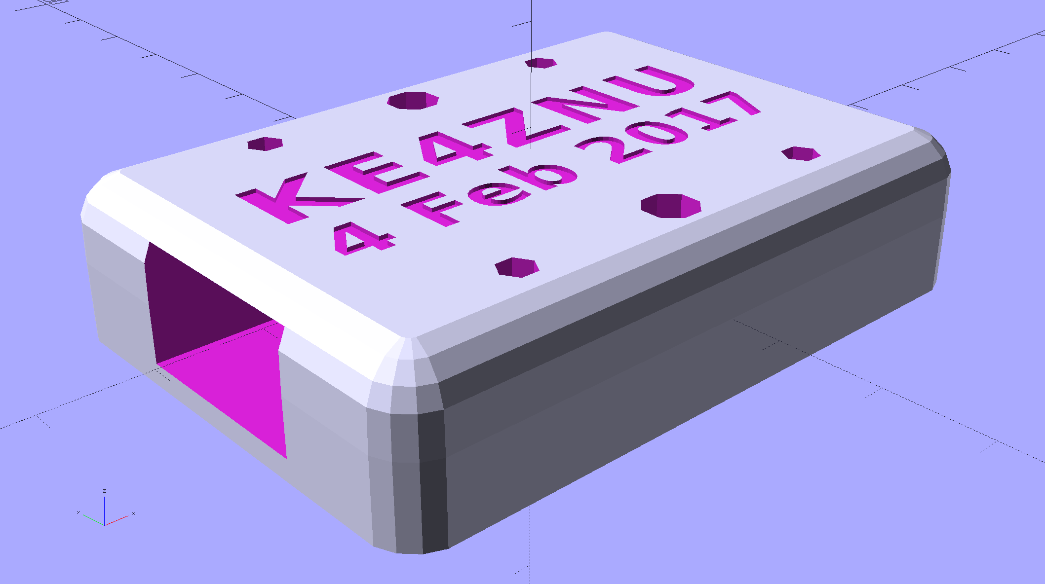
    Adapting the sewing machine cable clips for larger USB cables:

    LED Cable Clips - solid model
    LED Cable Clips – solid model

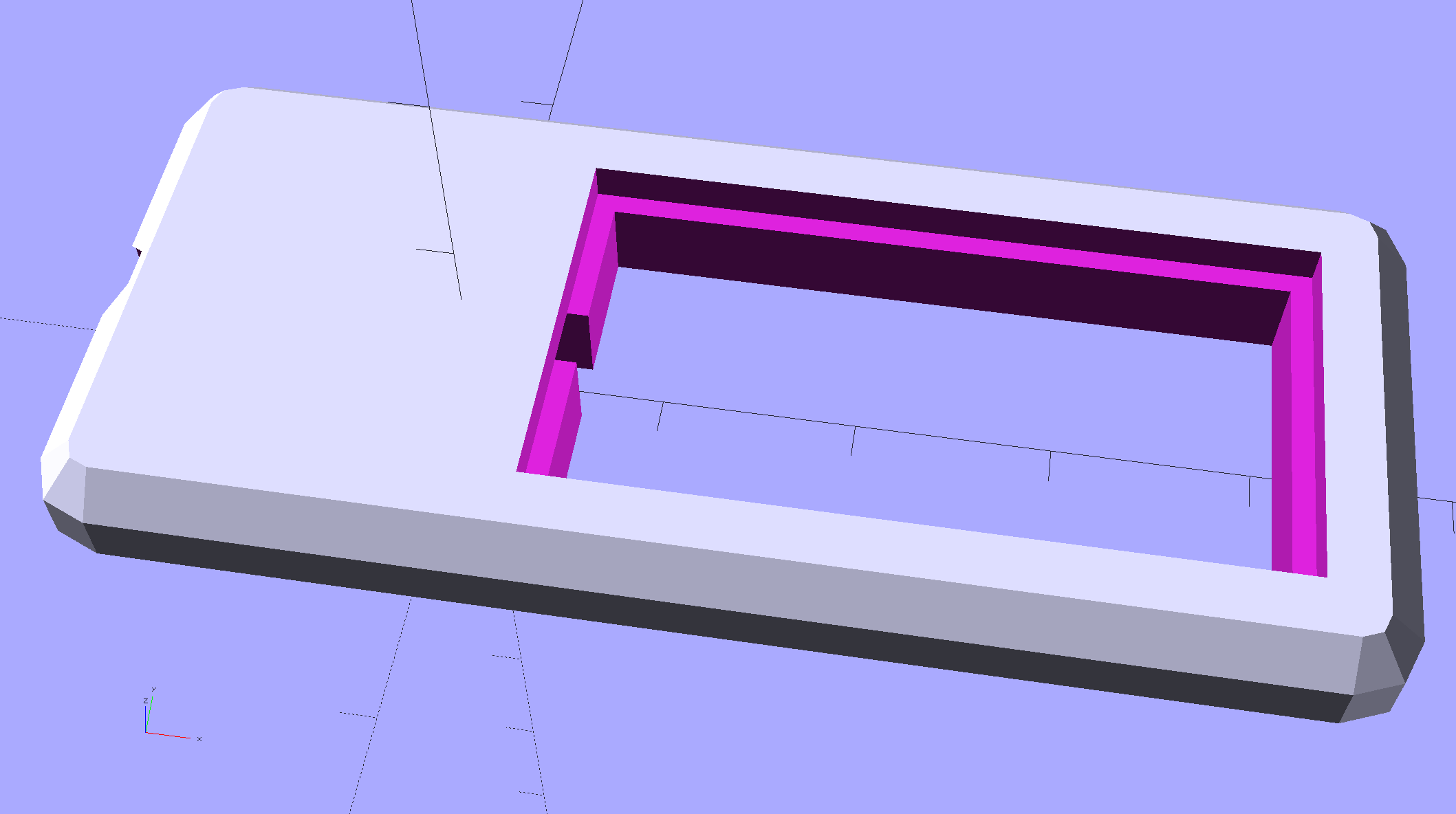
    The calculation positioning the posts wasn’t quite right; they now touch the cable OD at their midline and converge slightly overhead to retain it.

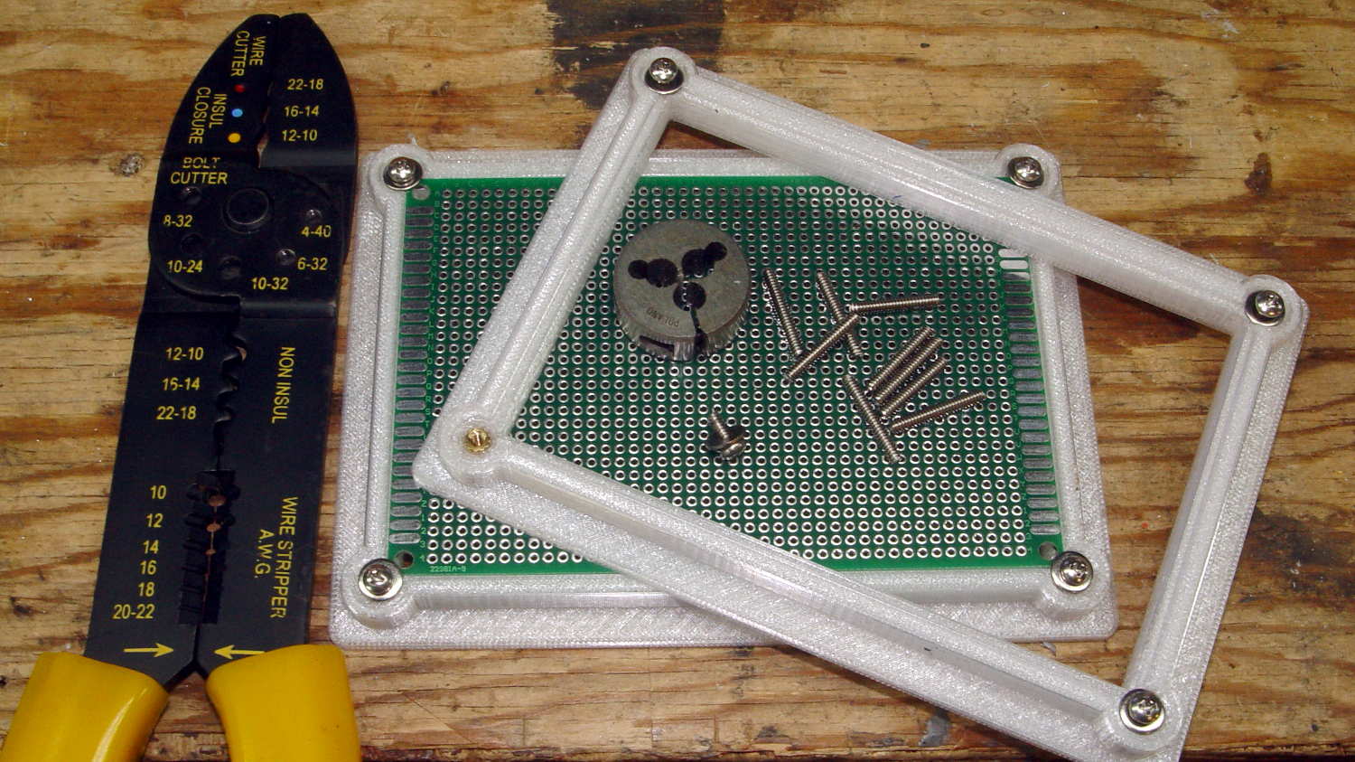
    They’re great candidates for sequential printing:

    LED Cable Clips - Slic3r - sequential print
    LED Cable Clips – Slic3r – sequential print

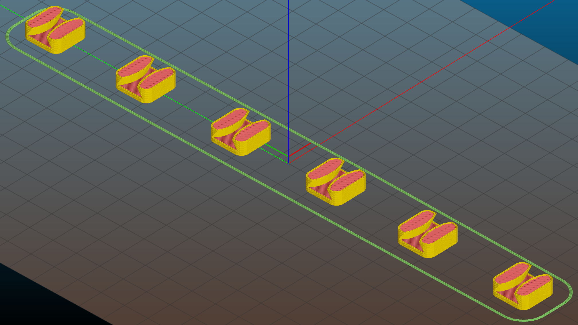
    With the basement at 14 °C, any cooling is too much: the platform heater can’t keep the bed above the thermal cutout temperature, the firmware concludes the thermistor has failed, and shuts the printer off. So I popped the four finished clips off the platform, removed the skirt, unplugged the fan, rebooted that sucker, and restarted the print.

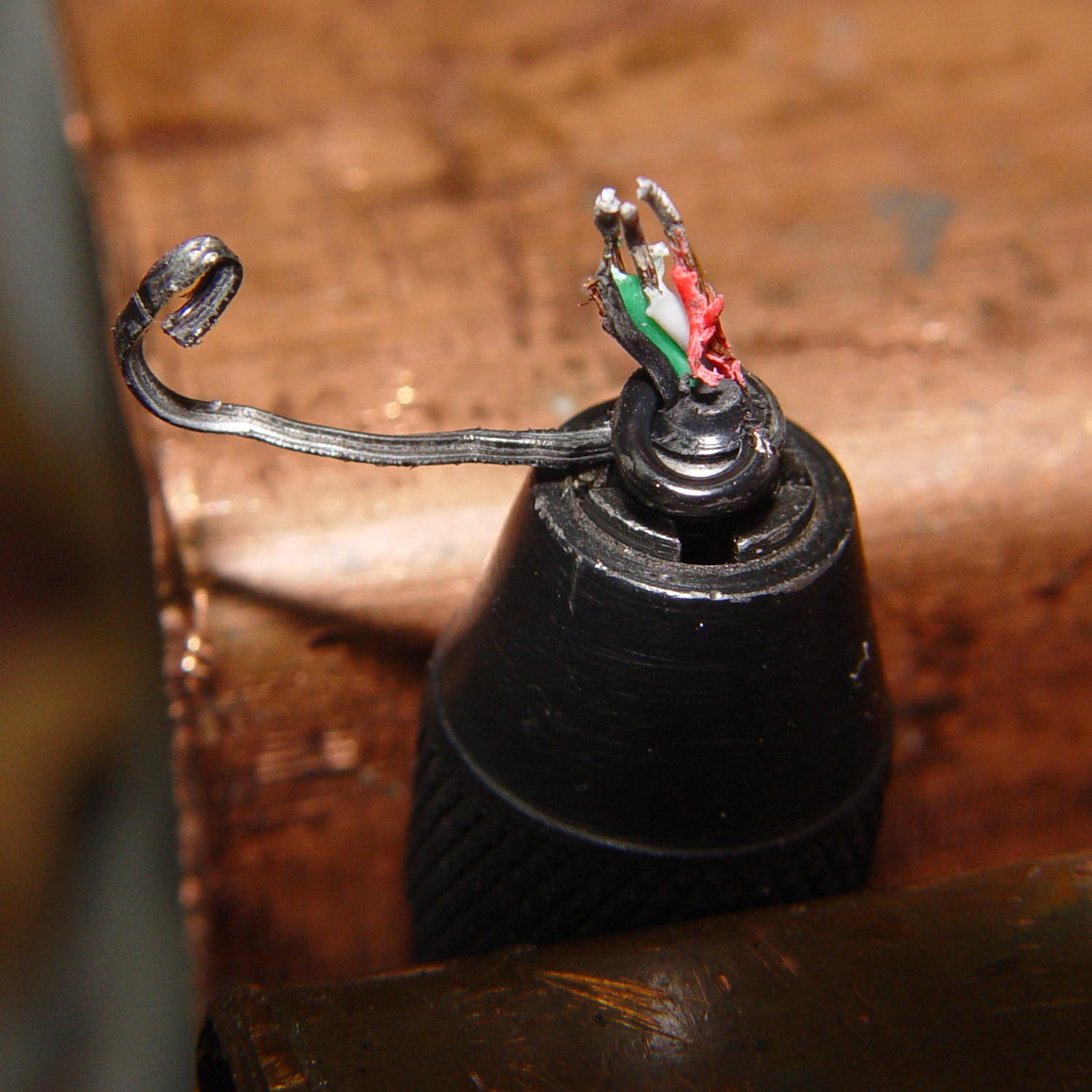
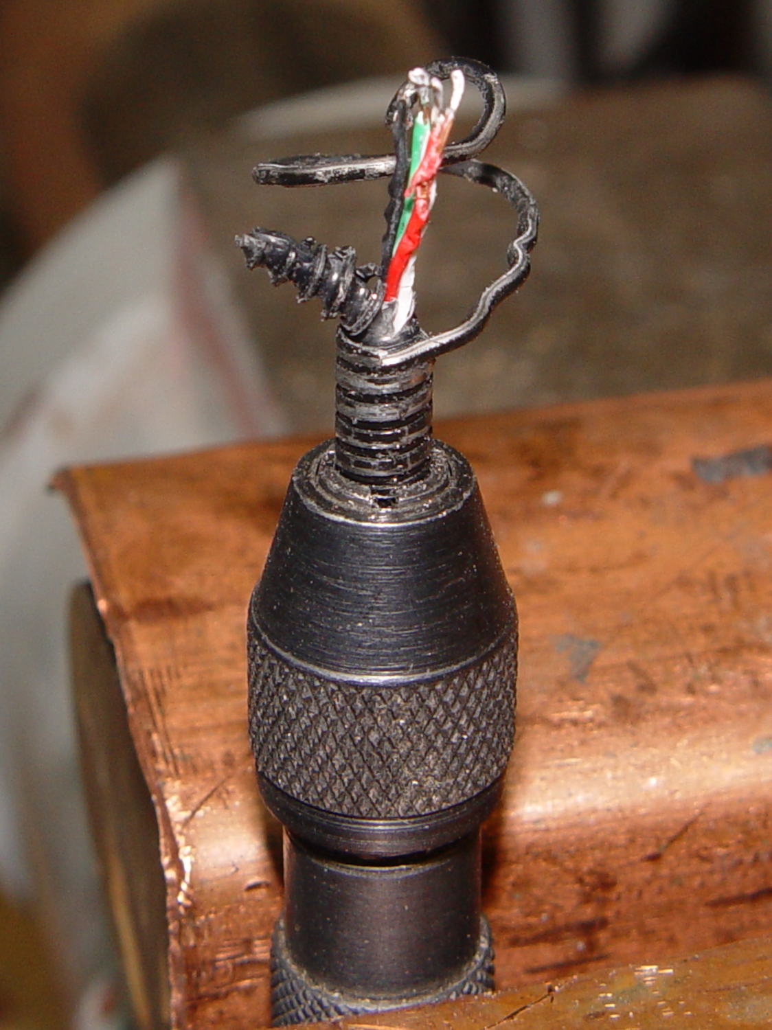
    One clip in the front keeps the cable away from the power switch and speed control directly below the gooseneck mount:

    USB Gooseneck Mount - cable clip
    USB Gooseneck Mount – cable clip

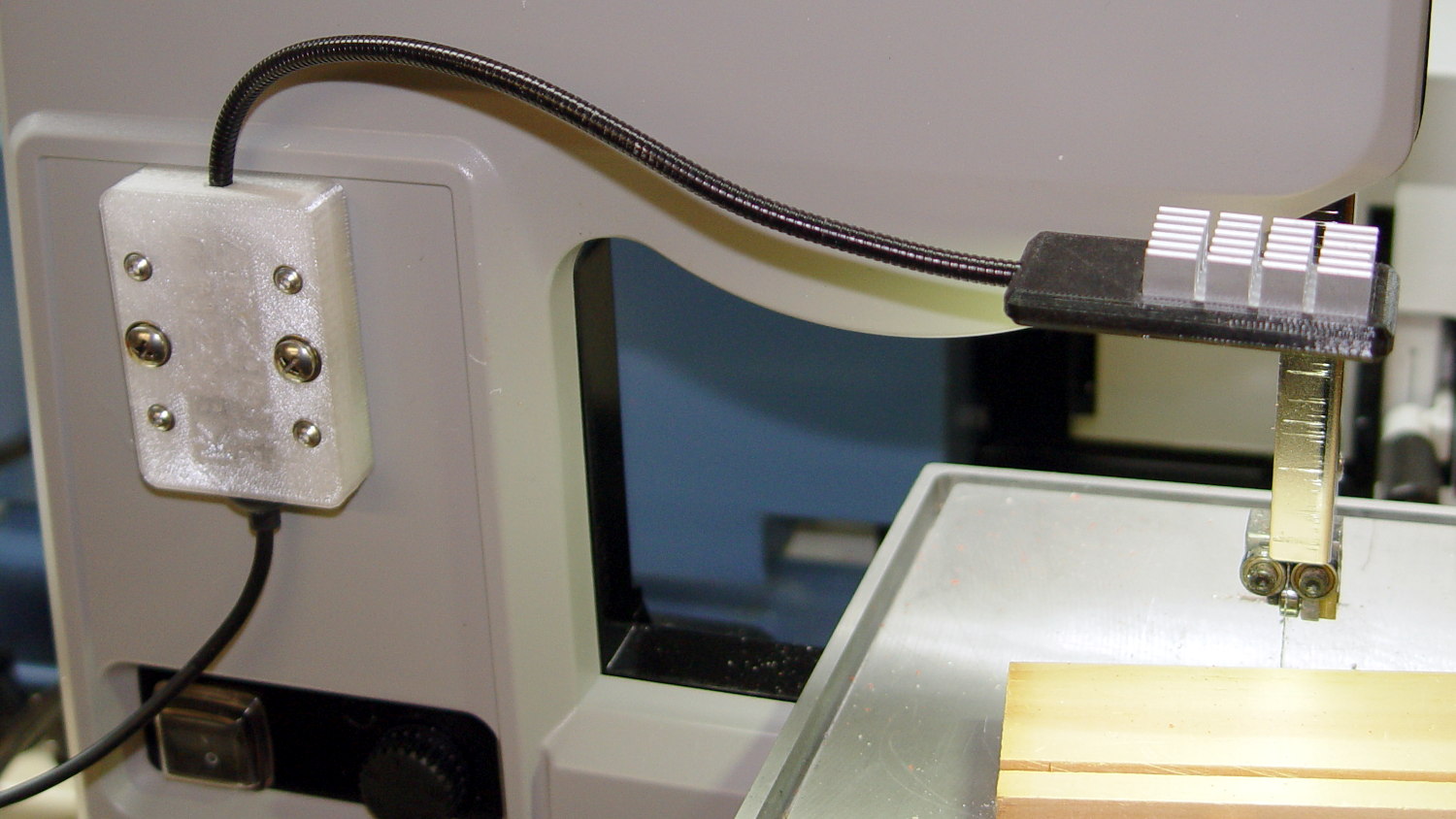
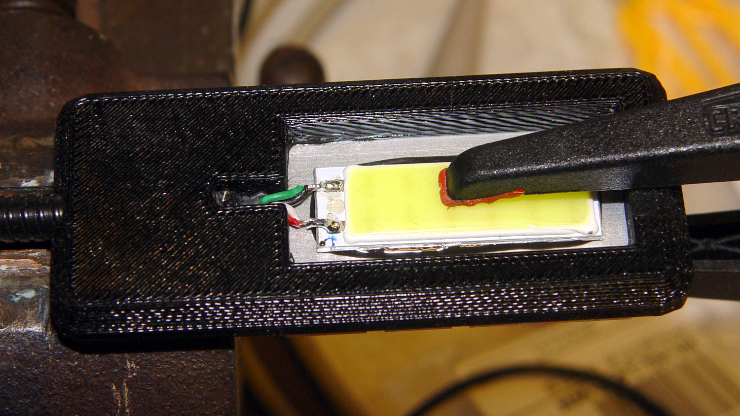
    A few clips in the back route the cable from the COB LED epoxied directly onto the bandsaw frame away from the motor enclosure:

    Bandsaw platform COB LED - cable clips
    Bandsaw platform COB LED – cable clips

    They’re mounted on double-sided foam tape. The COB LED on the frame isn’t anything to write home about, but you can see the foam tape peeking out around the clip base:

    Bandsaw platform COB LED
    Bandsaw platform COB LED

    Unlike those LED filaments, it seems you can gently bend the aluminum substrate under a COB LED.

    The bandsaw platform now has plenty of light: a fine upgrade!

    Yeah, you can buy stick-on cable anchors, but what’s the fun in that? These fit exactly, hold securely, and work just fine.

    The OpenSCAD source code as a GitHub Gist:

    // LED Cable Clips
    // Ed Nisley – KE4ZNU – October 2014
    // February 2017 – adapted for USB cables
    Layout = "Show"; // Show Build
    //- Extrusion parameters must match reality!
    ThreadThick = 0.25;
    ThreadWidth = 0.40;
    HoleWindage = 0.2; // extra clearance
    Protrusion = 0.1; // make holes end cleanly
    function IntegerMultiple(Size,Unit) = Unit * ceil(Size / Unit);
    //———————-
    // Dimensions
    Base = [15.0,15.0,6*ThreadThick]; // base over sticky square
    CableOD = 3.8;
    BendRadius = 5.0;
    CornerRadius = Base[0]/5;
    CornerSides = 4*4;
    NumSides = 6*3;
    //– Oval clip with central passage
    module OvalPass() {
    intersection() {
    hull()
    for (i=[-1,1], j=[-1,1])
    translate([i*(Base[0]/2 – CornerRadius),j*(Base[1]/2 – CornerRadius),0])
    rotate(180/CornerSides)
    cylinder(r=CornerRadius,h=Base[2] + 1.00*CableOD,$fn=CornerSides,center=false);
    union() {
    translate([0,0,Base[2]/2]) // oversize mount base
    scale([2,2,1])
    cube(Base,center=true);
    for (j=[-1,1]) // bending ovals
    translate([0,j*(Base[1]/2 – 0.125*(Base[1] – CableOD)/2),(Base[2] – Protrusion)])
    resize([Base[0]/0.75,0,0])
    cylinder(d1=0.75*(Base[1]-CableOD),
    d2=(Base[1]-CableOD)/cos(0*180/NumSides),
    h=(CableOD + Protrusion),
    center=false,$fn=NumSides);
    }
    }
    if (Layout == "Show")
    color("Red",0.3)
    translate([0,0,Base[2] + CableOD/2])
    rotate([0,90,0])
    cylinder(d=CableOD,h=2*Base[0],center=true,$fn=48);
    }
    //———————-
    // Build it
    OvalPass();
  • Bandsaw Worklight: USB Gooseneck Mount

    The bandsaw now sports a chunky mount for its gooseneck light:

    USB Gooseneck Mount - on bandsaw
    USB Gooseneck Mount – on bandsaw

    The gooseneck ends in a USB Type-A plug, so an ordinary USB extension cable can connect it to the hacked hub supplying 9 VDC:

    USB Gooseneck Mount - interior
    USB Gooseneck Mount – interior

    The plastic came from a slightly earlier version of the solid model, with one foam pad under the gooseneck’s USB plug to soak up the clearance. The four smaller holes, with M3 brass inserts visible in the bottom half (on the right), clamp the gooseneck connector in place against the foam; you could push it out if you were really determined, but you’d have to be really determined.

    If I ever build another one, it’ll sandwich the plug between opposing pads:

    USB Gooseneck Connector Mount - Slic3r preview
    USB Gooseneck Connector Mount – Slic3r preview

    The lettering on the block stands out much better in the solid model:

    USB Gooseneck Connector Mount - solid model - overview
    USB Gooseneck Connector Mount – solid model – overview

    Obviously, I need help with the stylin’ thing. This looks better, but with terrible overhangs for printing in the obvious no-support orientation:

    USB Gooseneck Connector Mount - solid model - rounded top
    USB Gooseneck Connector Mount – solid model – rounded top

    Anyhow, the USB extension cable (on the left) has plenty of clearance and pulls straight out of the housing, so I can remove the bandsaw cover without unwiring:

    USB Gooseneck Mount - assembled
    USB Gooseneck Mount – assembled

    The LED ticks along at 40 °C in a 14 °C basement, suggesting a thermal coefficient around 14 °C/W. Even in the summer months, with the basement around 25 °C, there’s no risk of PETG softening at 50 °C.

    I’ll epoxy a similar 1.8 W COB LED onto the curve of the bandsaw frame where it can shine on the left and rear part of the table; it doesn’t even need a case.

    The OpenSCAD source code as a GitHub Gist:

    // Gooseneck lamp for MicroMark bandsaw
    // Ed Nisley KE4ZNU
    // February 2017
    Layout = "Mount"; // Mount Show Build
    Gap = 5; // distance between halves for Show
    //- Extrusion parameters must match reality!
    ThreadThick = 0.25;
    ThreadWidth = 0.40;
    HoleWindage = 0.2;
    Protrusion = 0.1; // make holes end cleanly
    inch = 25.4;
    function IntegerMultiple(Size,Unit) = Unit * ceil(Size / Unit);
    //———————-
    // Dimensions
    Tap10_32 = 0.159 * inch;
    Clear10_32 = 0.190 * inch;
    Head10_32 = 0.373 * inch;
    Head10_32Thick = 0.110 * inch;
    Nut10_32Dia = 0.433 * inch;
    Nut10_32Thick = 0.130 * inch;
    Washer10_32OD = 0.381 * inch;
    Washer10_32ID = 0.204 * inch;
    ID = 0; // for round things
    OD = 1;
    LENGTH = 2;
    Insert = [3.0,4.9,2*ThreadThick + IntegerMultiple(4.2,ThreadThick)]; // M3 short brass insert
    CornerRadius = 5.0; // rounded mount block corners for pretty
    CornerSides = 4*4;
    RoundedTop = true; // true for fancy smooth top edges
    USBPlug = [39.0,16.0,8.3]; // plug, X from base of plug
    USBSocket = [28.0,20.0,11.5]; // USB extension, X from tip of socket
    USBMating = [-12.0,0,0]; // offset of plug base relative to block center
    Foam = [35.0,10.0,2.0 – 1.0]; // foam pad to secure USB plug (Z = thickness – compression)
    GooseneckOD = 5.0; // flexy gooseneck diameter
    MountScrewOC = 35.0; // make simple screw hole spacing for bandsaw case
    MountBlock = [10*round((USBPlug[0] + USBSocket[0] + 5.0)/10),
    10*round((MountScrewOC + Washer10_32OD + 5.0)/10),
    // 2*6*ThreadThick + IntegerMultiple(max(USBPlug[2],USBSocket[2]),ThreadThick)];
    16.0]; // thickness = 16 mm M3x0.5 button head screw
    echo(str("Block size: ",MountBlock));
    LegendDepth = 2*ThreadThick; // lettering depth
    //———————-
    // Useful routines
    module PolyCyl(Dia,Height,ForceSides=0) { // based on nophead's polyholes
    Sides = (ForceSides != 0) ? ForceSides : (ceil(Dia) + 2);
    FixDia = Dia / cos(180/Sides);
    cylinder(r=(FixDia + HoleWindage)/2,
    h=Height,
    $fn=Sides);
    }
    //– Mount
    module Mount() {
    difference() {
    hull()
    if (RoundedTop) {
    for (i=[-1,1], j=[-1,1])
    translate([i*(MountBlock[0]/2 – CornerRadius),j*(MountBlock[1]/2 – CornerRadius),0]) {
    translate([0,0,-MountBlock[2]/2])
    rotate(180/CornerSides)
    cylinder(r=CornerRadius,h=MountBlock[2]/2,$fn=CornerSides,center=false);
    translate([0,0,MountBlock[2]/2 – CornerRadius])
    rotate(180/CornerSides)
    sphere(r=CornerRadius,$fn=CornerSides,center=true);
    }
    }
    else {
    for (i=[-1,1], j=[-1,1])
    translate([i*(MountBlock[0]/2 – CornerRadius),j*(MountBlock[1]/2 – CornerRadius),0])
    rotate(180/CornerSides)
    cylinder(r=CornerRadius,h=MountBlock[2],$fn=CornerSides,center=true);
    }
    for (j=[-1,1]) // screws into bandsaw case
    translate([0,j*MountScrewOC/2,-(MountBlock[2]/2 + Protrusion)])
    rotate(180/8)
    PolyCyl(Clear10_32,(MountBlock[2] + 2*Protrusion),8);
    for (i=[-1,1], j=[-1,1]) { // clamp screws
    translate([i*MountBlock[0]/4,j*MountScrewOC/2,-MountBlock[2]])
    PolyCyl(Insert[ID],2*MountBlock[2],6); // clearance
    translate([i*MountBlock[0]/4,j*MountScrewOC/2,-(MountBlock[2]/2 + Protrusion)])
    PolyCyl(Insert[OD],Insert[LENGTH] + Protrusion,6); // inserts
    }
    rotate([0,90,0]) // gooseneck flexy cable
    rotate(180/6)
    PolyCyl(GooseneckOD,MountBlock[0],6);
    translate([USBPlug[0]/2,0,0] + USBMating – [Protrusion/2,0,0]) // USB plug outline
    cube(USBPlug + [Protrusion,0,0],center=true);
    translate([-USBSocket[0]/2,0,0] + USBMating) // USB socket outline
    cube(USBSocket,center=true);
    translate([(Foam[0]/2 + 5*ThreadWidth),0,-(Foam[2]/2 + USBPlug[2]/2)] + USBMating – [Protrusion,0,-Protrusion]/2) // foam padding recess
    cube(Foam + [Protrusion,0,Protrusion],center=true); // foam packing
    translate([(Foam[0]/2 + 5*ThreadWidth),0, (Foam[2]/2 + USBPlug[2]/2)] + USBMating – [Protrusion,0, Protrusion]/2) // foam padding recess
    cube(Foam + [Protrusion,0,Protrusion],center=true);
    render(convexity=5)
    translate([0,0,MountBlock[2]/2 – LegendDepth])
    linear_extrude(height=LegendDepth + Protrusion) {
    translate([0,5,0])
    text(text="KE4ZNU",size=8,spacing=1.10,font="Bitstream Vera Sans:style=Bold",valign="center",halign="center");
    translate([0,-5,0])
    text(text="4 Feb 2017",size=6,spacing=1.05,font="Bitstream Vera Sans:style=Bold",valign="center",halign="center");
    }
    }
    }
    //———————-
    // Build it
    if (Layout == "Mount") {
    Mount();
    }
    if (Layout == "Show") {
    translate([0,0,-Gap/2])
    difference() {
    Mount();
    translate([0,0,MountBlock[2]])
    cube(2*MountBlock,center=true);
    }
    translate([0,0,Gap/2])
    difference() {
    Mount();
    translate([0,0,-MountBlock[2]])
    cube(2*MountBlock,center=true);
    }
    }
    if (Layout == "Build") {
    translate([0,0.6*MountBlock[1],MountBlock[2]/2])
    difference() {
    Mount();
    translate([0,0,MountBlock[2]])
    cube(2*MountBlock,center=true);
    }
    translate([0,-0.6*MountBlock[1],MountBlock[2]/2])
    rotate([180,0,0])
    difference() {
    Mount();
    translate([0,0,-MountBlock[2]])
    cube(2*MountBlock,center=true);
    }
    }
  • Proto Board Holders: 80×120 mm

    Another stack of proto boards arrived, this time 80×120 mm, and I ran off another pair of holders:

    Proto Board Holder - 80x120 - tooling
    Proto Board Holder – 80×120 – tooling

    Not wanting to, ahem, screw around with the lathe, the screws got themselves shortened the old-fashioned way: by hand, with the screw cutter, then filed and passed through a 4-40 die to clean up the threads.

    Bah!

  • Bandsaw Worklight

    Having hacked back the end of the USB gooseneck extension, a tweak of the COB LED heatsink mount for my desk lamp produces a smaller version for a 1.8 W LED:

    Chip On Board Heatsink Mount - Bandsaw Lamp - solid model
    Chip On Board Heatsink Mount – Bandsaw Lamp – solid model

    That fits half of a random heatsink, bandsawed just to the far side of the middle fin and milled flat.

    Ream out the 5 mm hole with a #8 drill for a snug fit around the gooseneck, jam gooseneck in place, dab epoxy on the corners of the recess, mash the heatsink in place, solder wires to LED, smear epoxy on the aluminum backplate, clamp while curing:

    USB Gooseneck - LED assembly
    USB Gooseneck – LED assembly

    And it looks pretty good, if I do say so myself:

    USB Gooseneck - on bandsaw
    USB Gooseneck – on bandsaw

    The hook-n-loop tape holding the cable to the bandsaw gotta go, but should suffice until I conjure a better mount.

    The alert reader may wonder how a 9 V COB LED runs from a 5 V USB cable with nary a trace of a voltage booster to be seen. Well, that’s not really a USB cable any more; I paralleled the red+white and black+green wires for lower resistance, then hacked a 9 VDC power supply into an old USB hub:

    Hacked USB hub - PCB mods
    Hacked USB hub – PCB mods

    I ripped out the upstream USB plug, hotwired the 9 V supply where the 5 V USB wires used to be, soldered jumpers on the downstream sockets to short the outer two pin pairs together, razor-knifed the power leads going into the epoxy-blobbed USB controller, and declared victory:

    Hacked USB hub - in use
    Hacked USB hub – in use

    Admittedly, that “In Use” LED runs a bit brighter now.

    I have a few other tools on that bench in need of LED lights; when I build ’em, they can all plug into this hub. No reason to invent new connectors & cables & all that. It may need a power switch.

    Turns your stomach, eh?

    The OpenSCAD source code as a GitHub Gist:

    // Chip-on-board LED light heatsink mount for desk lamp
    // Ed Nisley KE4ZNU December 2015
    // February 2017 – rectangular COB, smaller heatsink
    Layout = "Show"; // Show Build
    //- Extrusion parameters must match reality!
    ThreadThick = 0.25;
    ThreadWidth = 0.40;
    HoleWindage = 0.2;
    Protrusion = 0.1; // make holes end cleanly
    inch = 25.4;
    function IntegerMultiple(Size,Unit) = Unit * ceil(Size / Unit);
    //———————-
    // Dimensions
    ID = 0; // for round things
    OD = 1;
    LENGTH = 2;
    Gooseneck = [3.0,5.0,15.0]; // anchor for end of gooseneck
    COB = [30.0,11.0,2.5]; // Chip-on-board LED module
    Heatsink = [37.1,19.2,10.0]; // overall
    HeatsinkBase = 2.0; // solid base below fins
    HSLip = 1.0; // width of lip under heatsink
    BaseMargin = 2*2*ThreadWidth;
    BaseRadius = 3*ThreadThick + Gooseneck[OD]/2; // defines slab thickness
    BaseSides = 2*4;
    Base = [(Gooseneck[LENGTH] + Gooseneck[OD] + Heatsink[0] + 2*BaseRadius + BaseMargin),
    (Heatsink[1] + 2*BaseRadius + 2*BaseMargin),
    2*BaseRadius];
    echo(str("Slab thickness: ",Base[2]));
    //———————-
    // Useful routines
    module PolyCyl(Dia,Height,ForceSides=0) { // based on nophead's polyholes
    Sides = (ForceSides != 0) ? ForceSides : (ceil(Dia) + 2);
    FixDia = Dia / cos(180/Sides);
    cylinder(r=(FixDia + HoleWindage)/2,
    h=Height,
    $fn=Sides);
    }
    //– Lamp heatsink mount
    module Lamp() {
    difference() {
    translate([(Base[0]/2 – BaseRadius – Gooseneck[LENGTH]),0,0])
    hull()
    for (i=[-1,1], j=[-1,1])
    translate([i*(Base[0]/2 – BaseRadius),j*(Base[1]/2 – BaseRadius),Base[2]/2])
    sphere(r=BaseRadius/cos(180/BaseSides),$fn=BaseSides);
    translate([(Heatsink[0]/2 + Gooseneck[OD]), // main heatsink recess
    0,
    (Base[2] + Heatsink[2]/2 – HeatsinkBase)])
    cube((Heatsink + [HoleWindage,HoleWindage,0.0]),center=true);
    translate([(Heatsink[0]/2 + Gooseneck[OD]),0,HeatsinkBase]) // lower lip to shade lamp module
    scale([1,1,2])
    cube(Heatsink – [2*HSLip,2*HSLip,0],center=true);
    translate([0,0,Base[2]/2]) // goooseneck insertion
    rotate([0,-90,0]) rotate(180/8)
    PolyCyl(Gooseneck[OD],Base[0],8);
    translate([0,0,Base[2]/2 + Gooseneck[ID]/2]) // wire exit
    rotate([180,0,0])
    PolyCyl(Gooseneck[ID],Base[2],6);
    translate([Gooseneck[OD],0,(Base[2] – HeatsinkBase – Protrusion)/2]) // wire slot
    rotate([180,0,0])
    cube([2*Gooseneck[OD],Gooseneck[ID],(Base[2] – HeatsinkBase + Protrusion)],center=true);
    }
    }
    //———————-
    // Build it
    if (Layout == "Show") {
    Lamp();
    }
    if (Layout == "Build") {
    }


  • USB Gooseneck: Unwinding

    The USB gooseneck extension consists of a spring-steel helix with an aluminum filler strip to smooth the outside:

    USB Gooseneck - filler unwound
    USB Gooseneck – filler unwound

    A pin vise holds the intact part of the gooseneck.

    The filler unwinds easily, but the spring required several bashes with a drift punch to loosen the first coil. The pin vise can’t apply enough grip to immobilize the spring, so you (well, I) bashed more-or-less radially outward, rather than at a tangent; that’s almost as difficult to do as to describe.

    After enough bashing to get a grip with sturdy needlenose pliers, the spring unwound in short sections, again applying force radially to avoid turning the gooseneck in the pin vise:

    USB Gooseneck - spring unwinding
    USB Gooseneck – spring unwinding

    The black helix aimed off to the side seems to be plastic from the USB shell injection-molded around the connector hardware.

    Chopping the spring with the tip of a hardened diagonal cutter (don’t do this with a copper-wire dike!) and bashing the tail ends back around the wire core produced a passable result:

    USB Gooseneck - reshaped ends
    USB Gooseneck – reshaped ends

    The black thing sticking out beyond the spring seems to be the jacket around the wires.

    All the conductors are the same diameter, which isn’t shouldn’t be particularly surprising.

  • NESDR Mini 2+ vs. Input Terminator

    A tiny handful of known-good-quality SMA terminators arrived from eBay:

    KDI T187GS - 50 ohm 1 W SMA attenuators
    KDI T187GS – 50 ohm 1 W SMA attenuators

    They’re described as KDI Triangle T187GS SMA Female Terminator, 50Ω, 1W, 0-4GHz. A bit of searching suggests MCE (whoever they are) borged KDI quite a while ago (their website, last updated in 2003, has been lightly vandalized) and a datasheet won’t be forthcoming.

    In any event, a NooElec NESDR Mini 2+ radio connected to a dual-band VHF-UHF antenna perched near a window shows this for a local FM station:

    FM 101.5 NESDR - direct
    FM 101.5 NESDR – direct

    Zooming to 5 dB/div:

    FM 101.5 NESDR - 5 dB steps
    FM 101.5 NESDR – 5 dB steps

    Installing the terminator at the end of an MCX-to-SMA adapter cable:

    FM 101.5 NESDR - 50 ohm terminator
    FM 101.5 NESDR – 50 ohm terminator

    Haven’t a clue about those tiny little spikes with the terminator in place, but they don’t line up with any of the high-energy inputs and are, most likely, junk brewed up within the radio. That’s with the RF gain set to 49.6 dB and AGC turned off.

    The hardware looks like this:

    NESDR with SMA attenuators
    NESDR with SMA attenuators

    The MCX connector on the radio isn’t the most durable-looking thing I’ve ever seen, so strapping the adapter cable to the case seems like a Good Idea. You can get an NESDR radio with an SMA connector for about the same price, which I’d have done if were available a while ago.

    The terminated input looks to be about -75 dBFS, about 15 dB below the between-station noise, and the carrier tops out around -25 dBFS, for a “dynamic range” of 50 dB. Oddly, that’s just about dead on the maximum dynamic range you can get from the 8 bit RTL2832U demodulator / ADC stuffed inside the NESDR: 8 bits × 6 dB/bit.

    It is not obvious to me the signal from a randomly chosen (albeit powerful) FM station should exactly fill the receiver’s dynamic range, particularly without AGC riding herd on the RF gain. Some hardware tinkering seems in order.

    The GNU Radio flow graph:

    FM Broadcast - GNU Radio flow
    FM Broadcast – GNU Radio flow


  • Monthly Science: WWVB Reception Sample

    Further results from the SDR-based WWVB receiver:

    60 kHz Receiver - preamp HIT N3 Pi3 - attic layout
    60 kHz Receiver – preamp HIT N3 Pi3 – attic layout

    Seven hours of mid-January RF, tight-zoomed in both frequency and amplitude, from 0350 to 1050 local:

    WWVB waterfall - N3 - 2017-01-24 1050 - composite
    WWVB waterfall – N3 – 2017-01-24 1050 – composite

    The yellow line of the WWVB carrier comes out 2 ppm high, which means the local oscillator chain is 2 ppm low. We know the WWVB transmitter frequency is exactly 60.000 kHz, translated up by 125 MHz to the N3’s tuning range; you can, ahem, set your clock by it.

    The blue band marks the loop antenna + preamp passaband, which isn’t quite centered around 60.000 kHz. Tweaking the mica compression caps just a bit tighter should remedy that situation.

    Given that input, a very very tight bandpass filter should isolate the WWVB carrier and then it’s all a matter of fine tuning…