It’s easier to remove the leadscrew while dismantling the carriage and apron, which requires removing the cover from the control box containing all the switches & knobs. Come to find out the “cover” actually holds all the gadgetry onto the headstock:
I want to replace the Power indicator with something visible in normal shop light; judging from the connectors and overall brightness, it’s a neon bulb inside a green housing.
Anyhow, the four screws holding cover to the headstock weren’t identical:

I thought the oddball screw was deliberate, perhaps fastening that corner to a plastic frame of some sort, but it turned out to be a quick fix for a boogered tap job:
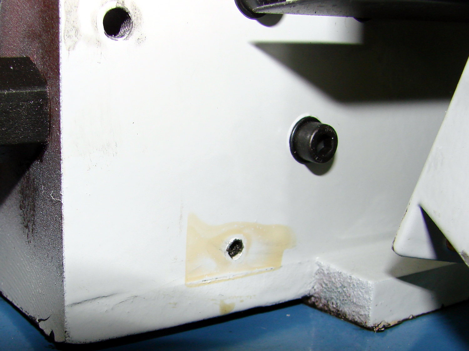
A bag of 4 mm knurled brass inserts will arrive in a while, after which I’ll drill out all four holes and epoxy inserts in their place. Might have to use stainless hardware, just for nice…

Comments
7 responses to “Mini-Lathe: Control Box Cover Screws”
And here I thought sheet metals screws were “universal threads” ;-)
“Bash to fit, file to hide, paint to cover…”
Ah, another variation, I like it! “Cut to size, beat to fit, paint to match”, is the one I use.
“The bigger the glob, the better the job” (usually applies to soldering and glue). “Grinder and paint makes me the welder I ain’t”.
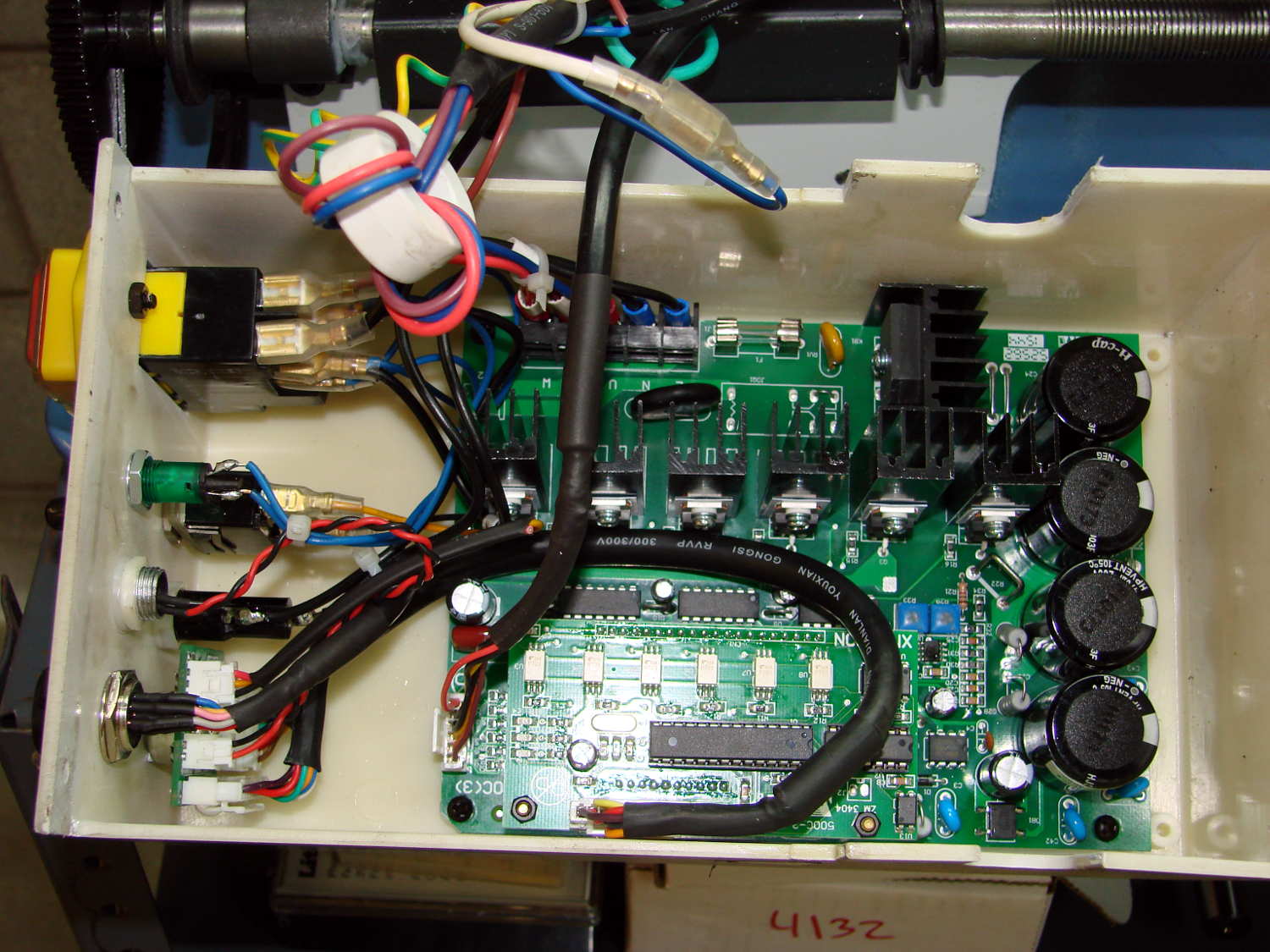
Have to say that I was not expecting to see 105 degree capacitors and a nice, beefy, common-mode choke on the power lead. Looks like the electronics team is doing rather better than their mechanical colleagues on this product.
It’s definitely not the worst chunk of electronics in the Basement Laboratory!
The mysterious connector (lower left foreground) suggests a programming interface, RPM pulses for a display, or diagnostic outputs. Can’t tell without doc and, of course, there is no doc.
[…] Two bags of knurled brass M4 inserts arrived from halfway around the planet, so I could fix the offending hole behind the LMS mini-lathe’s electronics box: […]