The hotrod build platform I’m using with the Makergear M2 consists of a PCB heater bonded to a glass plate, supported by three socket head cap screws soldered into the PCB. The print quality recently took a nosedive that seemed related to the first layer height, with which I fiddled more than usual, and finally the front of the platform became obviously, visibly, no-way-around-it far too high. Peering under the platform showed that the front support stud had pulled out of the solder fillet securing it to the PCB:
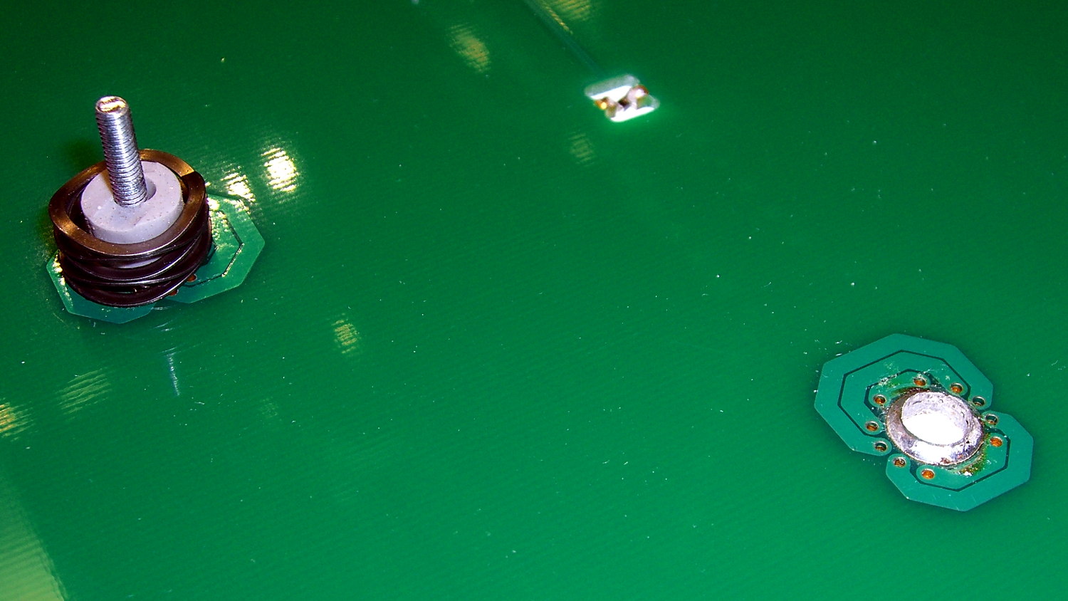
Those PCB patterns conduct the heater current around the mounting holes: the hotrod platform has better heat distribution than the OEM M2 platform.
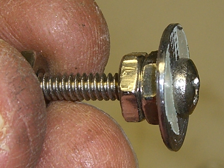
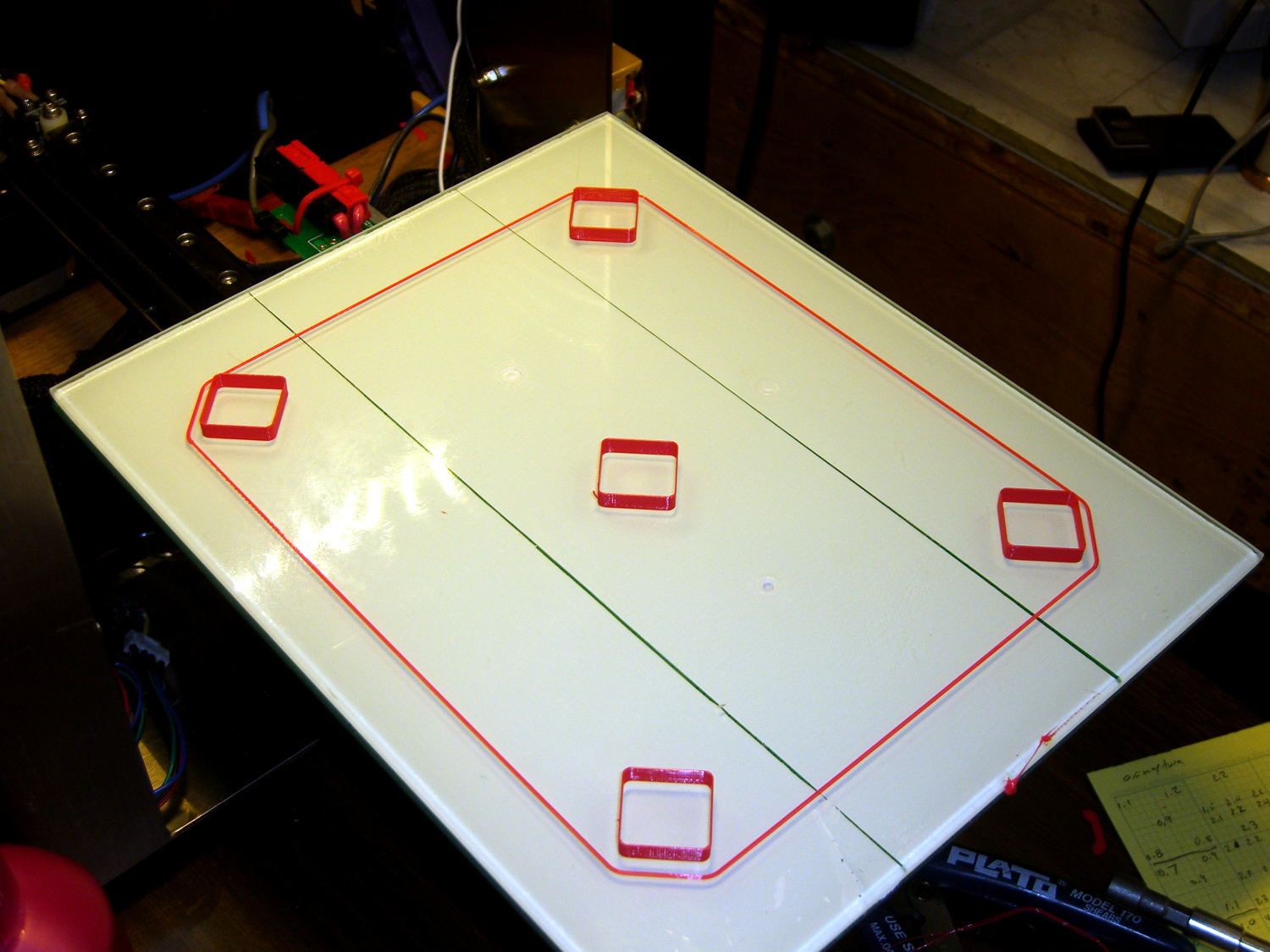
The offending screw didn’t go anywhere:

The wavy spring and silicone plug press on the PCB, so the solder fillet had to support all the stress. It seemed as though the solder hadn’t bonded to the stainless SHCS, but, rather than try to fix that, I decided to put a washer on the screw. That way, the spring bears on the washer and the screw head supports the strain, with the solder fillet responsible for holding the PCB and glass plate in position.
Alas, I didn’t have any washers small enough on the inside (3 mm) and big enough on the outside to support the springs, so I cut some out of a sheet steel scrap by drilling the center hole to the proper diameter, then applying a hole saw without its (far too large) pilot drill:
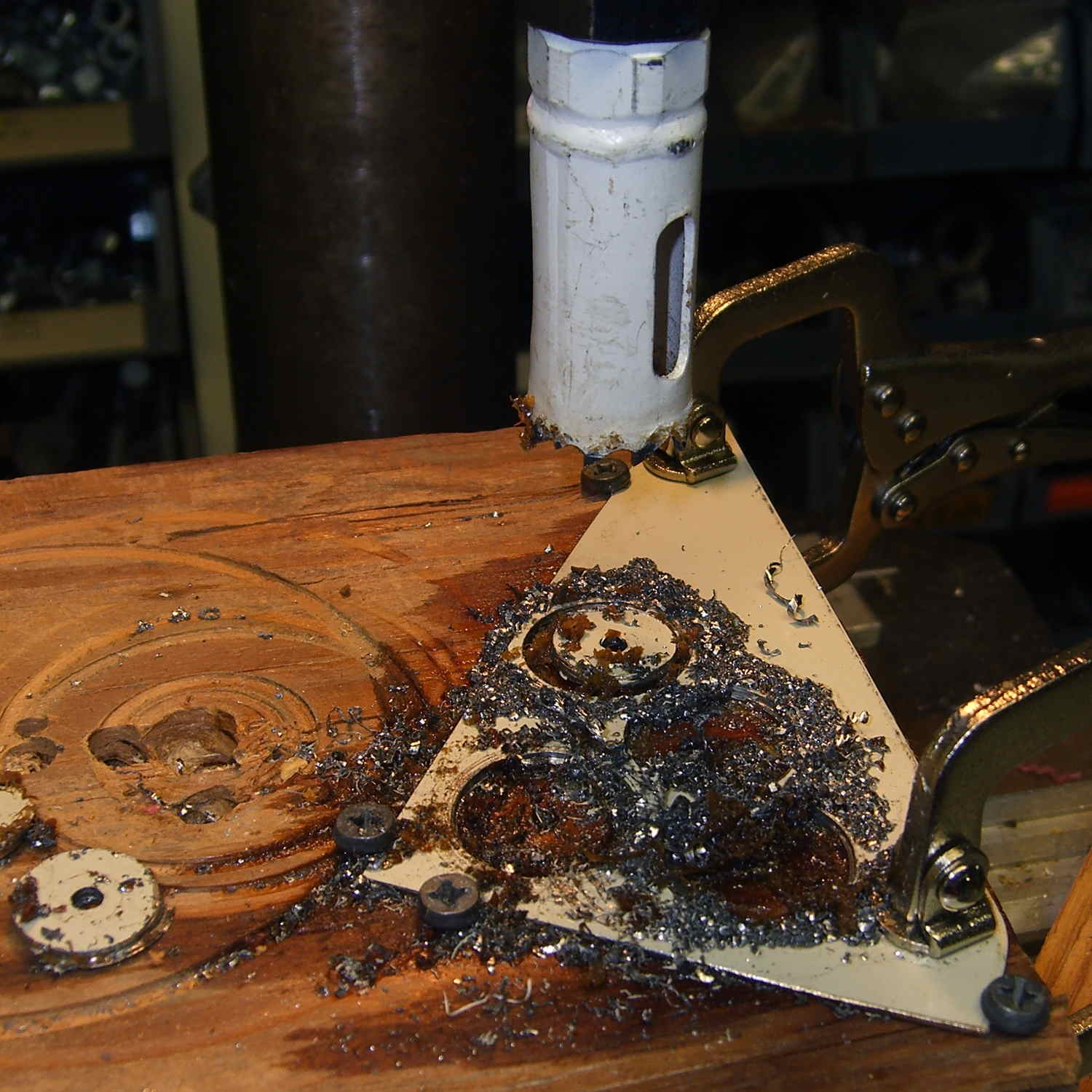
That’s a lethally bad idea, as the pilot-less saw can grab the sheet and toss it across the shop. Notice the screws holding the sheet down and absorbing the cutting torque, plus the two clamps enforcing the “stay put” edict.
The other problem with not having a pilot drill in the hole saw is that it’s not guaranteed to cut a cookie that’s concentric with the center hole. Instead of taking the time to make a pilot, I just drilled and cut a few extra washers, then picked the best three of the set for finishing:

Using a screw as a mandrel, I lathe-turned the OD of the better ones to make them nice and round:
Two of the three PCB support screws were in the right place (they hadn’t come loose), so I used the M2 as an alignment fixture for the third:
That’s a layer of good old JB Industro Weld epoxy, rated for much higher temperatures than the platform will ever see, between the big washers and the PCB. I buttered up the head of the errant screw and the inside of the solder fillet, shoved it in, and then stacked everything together. The small washers held the big washers perpendicular to the screws while the epoxy cured.
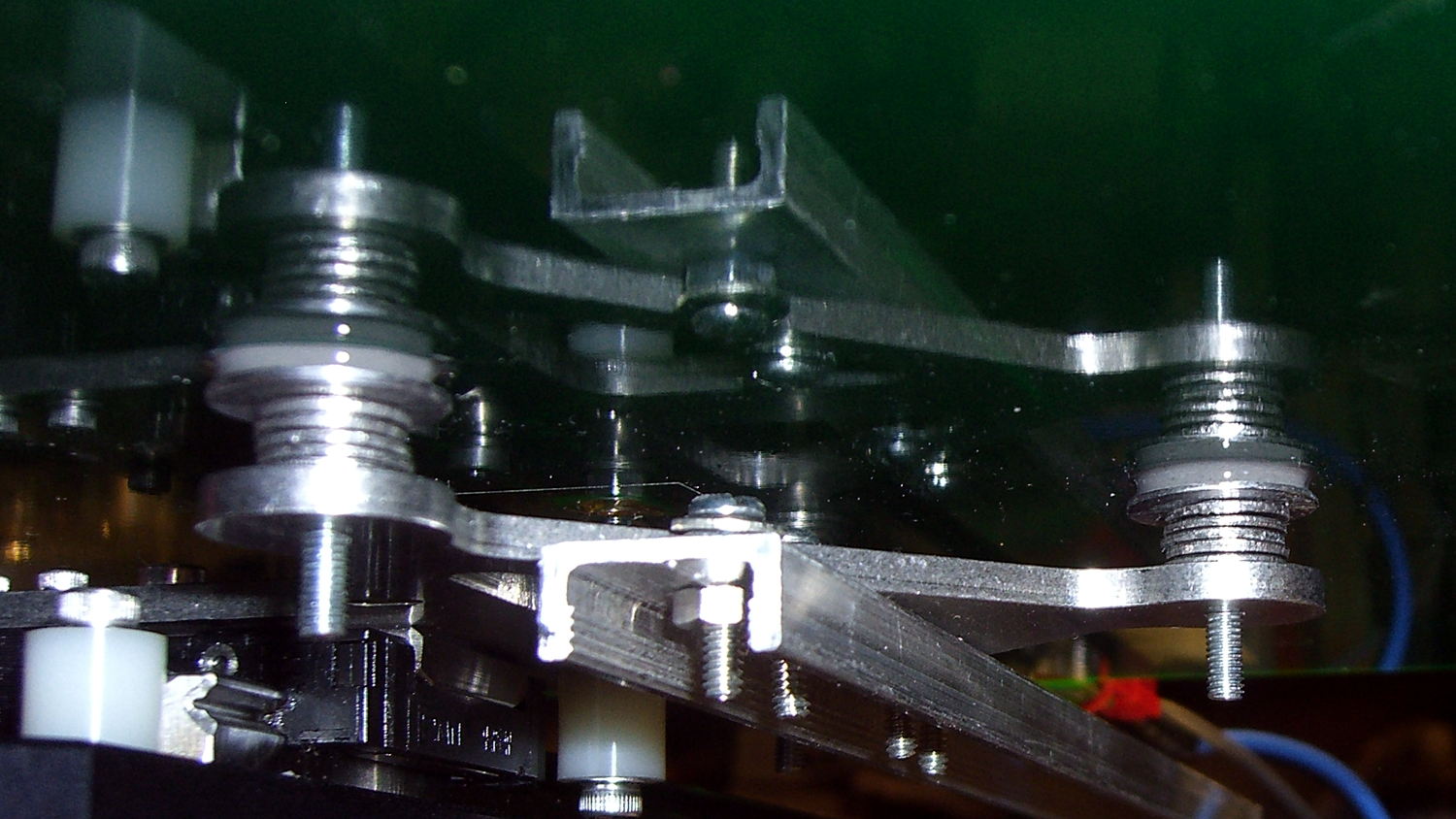
After that, I removed the small washers, reinstalled springs + silicone plugs, tightened the nyloc nuts, aligned the platform, ran off a few thinwall hollow boxes, tweaked the alignment, and it was all good:
The rest of the story: that mumble screw pulled loose on the Friday evening before the Mini Maker Faire on Saturday morning. I did all the shop work after supper, then let the epoxy cure overnight with the platform set to 95 °F while I got a good night’s sleep. Reinstalling and realigning the platform took the better part of half an hour around breakfast, after which I tore it all down, packed it all up, and headed off to the Mini Maker Faire.
In truth, that’s the most trouble I’ve had with the M2 and it’s not Makergear’s fault: it’s not their platform. After reinstalling the platform, the alignment was no big deal and it’s been stable ever since.

Comments
5 responses to “Hotrod M2 Platform Support Stud Repair”
At first I thought “why not just cut the circles and then center drill them” but then my brain came back on.
I think the modern-day method would be a CNC mill project: drill the center holes, CNC-mill the perimeter, file off the edges. But that’s a whole bunch o’ setup for three washers that I need right now…
Sorry if the answer to this is obvious, but why do you mess about with screw levelling et al and not do an automatic bed level offset like other printers? Printerbot Simple Metal springs to mind.
Mostly because I’m a big fan of stable mechanical adjustments, which is why I bought the M2. I’ve made some improvements to what’s already a pretty good mechanical design, with the result that there’s very little messing around to be done.
The probe-and-correct routines depend on zero backlash and stiction in the Z axis, plus enough Z axis bandwidth to keep up with XY motion. The last time I ran the numbers, that required dialing back the XY speeds / accelerations to match the Z leadscrew values: when the nozzle can cross the platform faster than the Z axis can respond, there’s a problem with auto-leveling.
On the other paw, I’d like to see contemporary numbers to show I’m wrong… [grin]
[…] The skirt thickness varies from 0.15 mm in the X-Y+ corner to 0.25 mm at X+Y-. That’s so close I’m not even tempted to adjust the screws. […]