I hauled the Kenmore 158 sewing machine and controller to a Squidwrench meeting for some current measurements (and, admittedly, showing it off) while schmoozing. After hauling it home and setting it up on my bench again, it didn’t work: the motor didn’t run at all.
While doing the usual poking around under the cover, I spotted this horrifying sight:
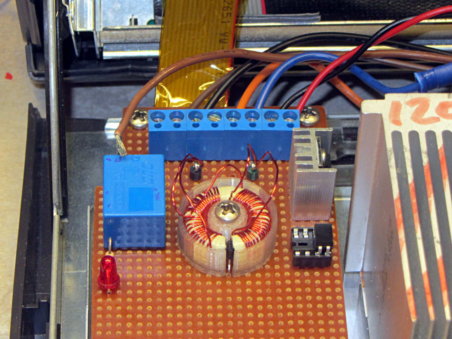
The brown insulation tells you that’s a hot wire from the AC line and, in fact, it’s coming directly from the line fuse; it’s live whenever the plug is in.
It’s a stranded wire to allow flexing without breaking, but that same flexibility allows it to squeeze its way out of a tightly fastened screw terminal. In principle, one should crimp a pin on the wire, but the only pins in my heap don’t quite fit along the screw terminal block.
This sort of thing is why I’m being rather relentless about building a grounded, steel-lined box with all the pieces firmly mounted on plastic sheets and all the loose ends tucked in. If that wire had gone much further to the side or top, it would have blown the fuse when it tapped the steel frame. The non-isolated components on that board are facing you, with those connections as far from the terminal block as they can be.
Engineers tend to be difficult to live with, because we have certain fixed ways of doing things that are not amenable to debate. There’s probably a genetic trait involved, but we also realize that being sloppy can kill you rather quickly; the universe is not all about pink unicorns and rainbows.
In fact, the universe wants you dead.
Now, go play with those goblins and zombies tonight…
Memo to Self: Tighten those terminals every now and again. A wire will come loose shortly after you forget to do that, of course.

Comments
13 responses to “Halloween Horror: Line Voltage on the Loose!”
Or buy a selection of ferrules and a good crimped to dress the end of that wire for the terminal block… That’s my “set way of doing things”.
My “selection” includes too large and too small.
Obviously: I. Need. More. Stuff. [sigh]
I don’t like doing anything with untinned stranded wires, so I’d have tinned this; but even tinned ends get swaged in screw terminals. Thoughts about that versus a pin crimped on?
The trouble with soldering the tips is that puts a big stress riser where the strands leave the solid section: a few cycles of wiggling, the strands break, and the wire comes free with strands sticking out of the insulation. POW!
Crimped pins avoid that riser, but require owning the proper crimping tool to do the job right. The pins are cheap, the tools extravagant, and … well, you see what happens when the job isn’t done right.
I’ll look when I get home, if I remember, but I found a company that makes crimp tools that do a dual (wire and insulation) crimp in one pass, with a tension spring so they’re repeatable, and can handle two different sizes of pin per crimp tool, for about $25 per tool. They’re certainly not molex (getting the pin into the crimp tool is way more irritating) but they’re also ten steps above the single-crimp-plus-stripper-cutter-screw/bolt-cutter ones.
I suspect it’s this: http://www.pololu.com/product/1929
Not the best, but good enough that now I crimp everything rather than using screw terminals or hard-soldering wires to boards.
Dear Santa:
I’ve been good this year, apart from some sloth and gluttony that, really, could happen to anybody…
And it will succeed, eventually. [grin]
I was thinking of the multisegement folding stepladder that folded itself when I was on it. Minor scraped and bumps, even though it was on concrete. I’ve had this ladder since 199X and just discovered it was recalled–in 1998… [wince] No surprise that the company is long gone. Oh well, more cargo for my next scrap metal run.
Re: fully tinned wires in a screw block. I’ve had them work out, since they don’t adequately deform under the screw pressure. Depends on the amount of force you can apply. We used to use Winchester connectors for an application where I worked, and the crimped pins worked fine if 1) you used the right sized pins for the wire and 2) the connector hood did the strain relief properly. (The assembly used 120+ pins per cable, and we had to disconnect it frequently.)
I bet you could print a strain relief ?!
Two blocks of plastic, screwed together, with the wires running through the middle before they enter the screw terminal.
Anchored by a pin in the sole unused screw terminal.
I like it!
The guidance I’ve been able to find on the cage contacts is to twist the strands, but do not tin. Apparently, the cage clamp terminal block is designed to flatten stranded wire for increased contact area and the tinning prevents that. I have seen a number of cases where the assembler had put a big blob of solder on the wire and the solder moved enough over time to cause a loose connection.
I twist the strands tightly so they hold their shape rather than splaying out, and that seems to work well for me.
I’ve been gently twisting them to get all the strands lined up, but that’s obviously inadequate. I’ll twist them a bit more enthusiastically and see how that works.
To be fair, I’ve used this type of connector before, with similar stranded wire and my feeble twist, and it’s all worked well enough until now. Of course it fails with the hottest of hot wires…
The biggest problem with soldering wire ends that go into screw terminals is creep. Solder creeps, and will dutifully relieve the stress that keeps the screw terminal tight. There’s no way around ferrules, I’m afraid. Of course a ferrule only works on one wire size, so you’ll end up with a proliferation of them. I know something about that :)