Ed Nisley's Blog: Shop notes, electronics, firmware, machinery, 3D printing, laser cuttery, and curiosities. Contents: 100% human thinking, 0% AI slop.
I carry around an ancient Zire 71, from the time before PDAs merged with phones and PCs to become fashionable objects of desire.
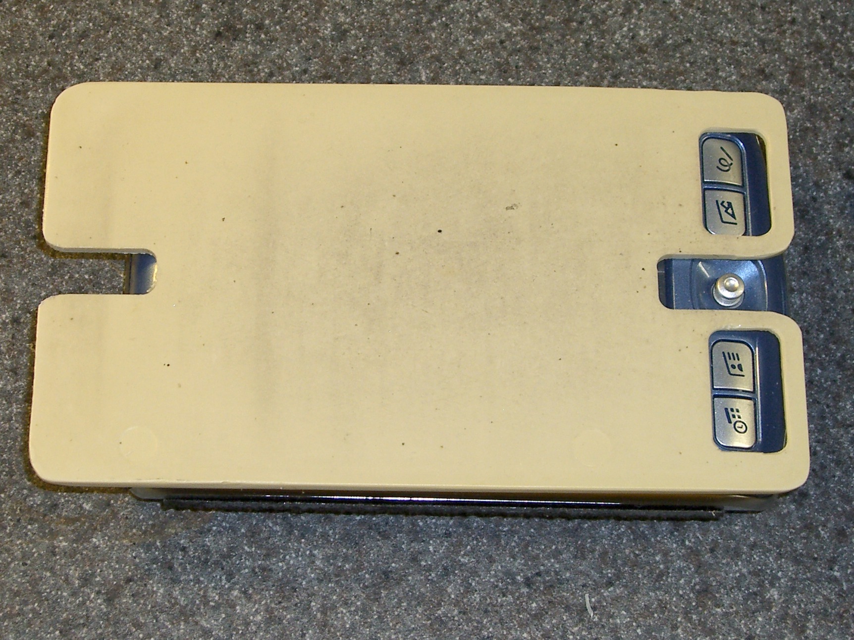
Anyway, it turns out that the buttons on the front are remarkably easy to squash in your pocket: the poor thing spends a lot of time turning itself on and off. I machined a plate with two holes for the four buttons and a lengthwise recess with two notches for the joystick selector. The whole affair slides into the pouch Mary made for it and works fine.
I tweaked the thing a bit when I got a replacement Zire a few months ago; the grippy tape I put on the sides seemed to be just large enough to force the joystick against the protector while sliding it into the pouch. Now that’s not a problem.
Zire 71 protector in place
This is in the nature of documentation, just in case I need something like this ever again. I found these pix while looking for something else …
Having obtained eyeballometric measurements from the case, the next step was to doodle some shapes on graph paper and pencil in the dimensions. My motivation for not using CAD is simple: it’s easier (for me, at least) to doodle using a pencil.
The outside of the case had pretty much the same features.
Pack Layout – External
The inside, of course, bore no resemblance to the battery pack; the shoulder and whatnot will support the circuit board.
Pack Layout – Internal
The original battle plan was to build the case in at least two layers, simply because it had to be so deep the Sherline couldn’t reach to the bottom with any rational end mill. It would probably make more sense to glue up four sides on a machined bottom, but that requires actual skill.
This became the Front layer, with Front and Rear faces. The Rear layer attaches to the back of this one. In this picture, the Front layer is on the bottom, taped to the radio.
ICOM IC-Z1A with GPS+Audio Interface
The two layers peeled apart, with the Front layer to the right. You can barely see the internal shoulder and external tabs.
As described there, I made a fixture and a small plate to hold 2.5 mm and 3.5 mm plugs in the proper alignment for the mic & speaker jacks on our ICOM IC-Z1A HTs. Knowing I was going to rebuild the interface boxes, I made several spare plates and tucked them into a small bag against future need.
Jack Plates – Oblique
Time passes.
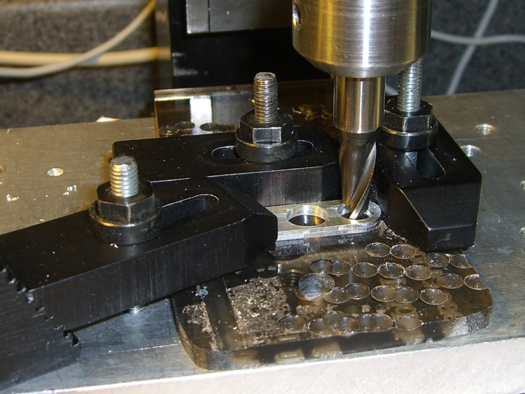
Come to find out that the new gratuitously gold-plated 2.5 mm plugs in my stash have a slightly thicker front plate that doesn’t quite fit into the recess I milled in the plates for the old nickel-plated plugs. So I set up a little nest in on the Sherline’s table, snuggled each plate into the corner, and poked a 9/32-inch end mill 1 mm down into the plate. The net change was a 0.5 mm deeper recess. Sheesh.
Milling the plug plate recess
I’d originally create the recess with helical milling, but I recently uncovered a stash of shiny-new end mills in a box: 9/32 is 7.31 mm, just about exactly what you want for a 7-mm dia plug front plate surrounded by a blob of fast-curing epoxy.
Plugs epoxied into plate
This epoxy just holds the plugs in the right position for wiring and initial testing. After the cable checks out, I’ll smoosh a blob of epoxy putty around the whole thing as before.
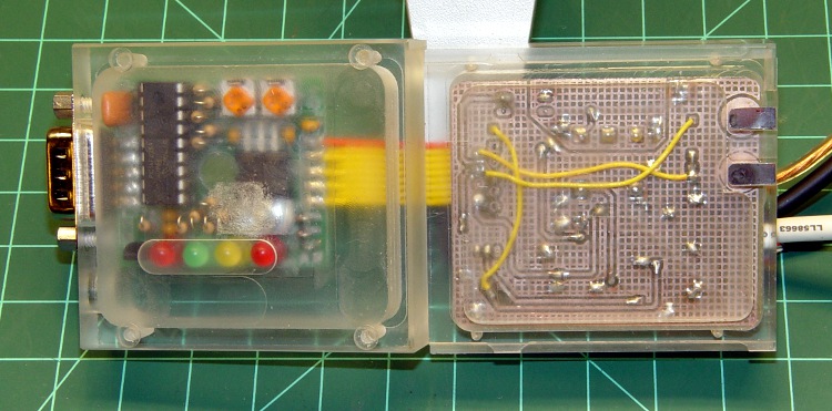
The circuit board is 30-mil, double-sided, half-ounce (I think) copper on glass-fiber stock, direct-etched by rubbing ferric chloride solution onto it with a sponge.
The top copper image (on the left) is reversed so it comes out correctly when you’re doing toner-transfer etching.
I didn’t bother with a silkscreen, because I don’t have a soldermask and there’s no room for text around the parts anyway.
The four vias at the corners mark the edge of the board. Trim it with tinsnips (or a shear if you have one), then introduce it to Mr Belt Sander until the edges pass directly through the middle of those via holes. Round the corners a bit so they fit into the case recess atop the mounting shoulder.
Put Z-wires in the small round vias (the ones that don’t have any other traces) to connect the top and bottom ground planes.
Put Z-wires in the other round vias to connect a top-side signal to the corresponding bottom-side trace.
There are three jumper wires across the bottom; with only two layers I don’t get all bothered about embedding the last few. Those vias are square.
I don’t have any way to do plated-through holes, so solder the wires to both sides of any vias with traces on both planes. I admit I missed two of them on the TT3 ribbon cable.
The big empty space around the positive power terminal prevents the ring-lug connector from shorting to the ground plane. Now that I think of it, there’s no need for an empty space on the bottom copper, but it doesn’t do any harm.
You’ve seen bits & pieces of this in the previous weeks and months: now it’s up and running!
Admittedly, this is brassboard hardware; I must now build three final versions for our bikes incorporating all the tweaks & adjustments. But it’s time to write this stuff down so I can find it again … and perhaps you can use some chunks, too.
I don’t have an instruction manual to go along with this, nor is there a parts kit available. You’ll certainly want to modify everything for your own purposes; the circuit board and case certainly won’t fit whatever HT you’re using!
Over the next several days, I’ll be describing & documenting the tricky parts… in no particular order, because I’m not going to sort my notes & photos ahead of time.
One of our nice aluminum water bottles hit the floor and, of course, the tiny little hinge shattered. It’s some wonderful engineering plastic, but just look at the leverage you can apply to those few millimeters of material. This is the sort of repair that can’t possibly be economically justified, but it pisses me right off when something that should be rugged turns out to be this fragile.
The 2 mm steel hinge pin snapped the molded plastic center post of the hinge off the cap; we found the larger fragment, but the smaller one may lurk under the refrigerator for quite some time. Nothing bonds to this plastic and, if the post broke in the first place, adhesive isn’t going to help.
Broken hinge
Some doodling showed that a replacement hinge post should be machineable. The general idea was to square up the remaining chunk of the post, then attach a replacement hinge pivot with a screw. The post is almost exactly 1/4-inch thick, call it 6.2 mm, which means the right-angle feature under the pivot ought to keep the whole affair from twisting.
Water Bottle Hinge
I planned to leave the left side unmachined and cut it to fit by hand, but then figured, eh, just make it happen. I also expected to leave the area around the screw a lot thicker, with a neat counterbore around the head.
This being a bash-to-fit, file-to-hide kind of project, I wrote a snippet of G-Code (at the bottom of the post) to chew out the part from a sheet of Lexan, then did the perpendicular hole & countersinking with manual CNC.
No pix of that; I was working in a white-hot fury. Basically, I double-sticky-taped a slab of Lexan to a sacrificial sheet, clamped it to the tooling plate, and had at it with a 2 mm end mill. Cutting a 6.4 mm sheet with a 2 mm end mill is a bit iffy, as the flutes are just barely that long; the mill was armpit-deep in swarf and I was dribbling water into the cut to keep it cool.
By the time I stopped for a picture, the situation looked like this.
Replacement hinge part
For what it’s worth, that’s the second part. I had to lower the screw head below the top of the half-round feature on the left end in order to clear the cap. That’s what CNC is really good for in my shop: make another one, just like the other one, only different exactly like that.
I drilled a #50 (2-56 tap) hole in the cap pretty much by eye, using laser targeting to touch off.
Laser aligning to hinge stub
The hole wound up minutely too far inboard, but some filing cleaned up the stub edge and it was all good. I started the tap in the mill, held loosely in the chuck and turning it with my fingers, then finished up on the bench.
The screw hole goes all the way through the cap. I filed the screw down so the end sits flush at the bottom of the cap, where the silicone rubber gasket should seal firmly against it.
Here’s what the hinge looks like with all the bits assembled. The spring bears on the screw head, which makes the cap open with more snap than before. I put a little counterbore under the screw head, even after lowering it, to reduce the spring tension.
Rebuilt hinge
The cap has a spring-loaded latch that never worked very well in the first place and this repair didn’t improve it. As nearly as I can tell, the molded ledge on the cap has a rounded edge that the latch simply cannot engage. This is beyond even my level of interest; Mary was accustomed to using the wire snap to hold the cap closed and that practice will continue.
Works well enough for us and I got some Quality Shop Time on a rainy afternoon.
The G-Code uses a slightly modified & simplified version of the tool length probe routines. I’m not convinced that using the G59.3 coordinate system is the right way to go, but everything else seems worse.
(Water bottle hinge repair)
(Ed Nisley - KE4ZNU - June 2010)
(Rough-cut 1/4-inch plate with clamp at +Y)
(Sacrificial plate below, double-stick tape to secure)
(Tool change @ G30 position above length probe)

(-- Global dimensions & locations)

#<_Stock_Thick> =        6.5                    (overall thickness)

#<_Traverse_Z> =        1.0
#<_Safe_Z> =            30.0                (clamp clearance)

(-- Section controls)

#<_Do_Outline> =    1
#<_Do_Drill> =        1

(-------------------)
(-- Initialize new tool length at probe switch)
(    Assumes G59.3 is still in machine units, returns in G54)

#<_Probe_Speed> =        250            (set for something sensible in mm or inch)
#<_Probe_Retract> =        1            (ditto)

O<Probe_Tool> SUB

G49                    (clear tool length compensation)
G30                    (to probe switch)
G59.3                (coord system 9)

G38.2 Z0 F#<_Probe_Speed>        (trip switch on the way down)

G91
G0 Z#<_Probe_Retract>            (back off the switch)
G90

G38.2 Z0 F[#<_Probe_Speed> / 10]    (trip switch slowly)

#<_ToolZ> = #5063                    (save new tool length)

G43.1 Z[#<_ToolZ> - #<_ToolRefZ>]    (set new length)

G54
G30                    (return to safe level)

O<Probe_Tool> ENDSUB

(-------------------)
(-- Initialize first tool length at probe switch)

O<Probe_Init> SUB

#<_ToolRefZ> = 0.0        (set up for first call)

O<Probe_Tool> CALL

#<_ToolRefZ> = #5063    (save trip point)

G43.1 Z0                (tool entered at Z=0, so set it there)

O<Probe_Init> ENDSUB

(-------------------)

(-- Get started ...)

G40 G49 G54 G80 G90 G92.1 G94 G97 G98        (reset many things)

M5

(msg,Verify clamp to +Y, stock taped down)
M0

(msg,Verify X=0 at left edge, Y=0 on finished centerline)
M0

(msg,Verify tool touched off at Z=0 on surface)
M0

O<Probe_Init> CALL

T0 M6                            (ensure first tool change pauses)

(-- Drill the hinge pin hole)

#<Pin_X> =                7.0
#<Pin_Y> =                0.0

#<Drill_Dia> =            2.06    (Drill diameter)
#<Drill_Num> =            46        (Drill number)
#<Tool_Num> =            146        (Tool number)
#<Drill_Radius> =        [#<Drill_Dia> / 2]
#<Drill_RPM> =            3000
#<Drill_Feed> =         [#<Drill_Dia> * 100]

#<Drill_Depth> =        [#<_Stock_Thick> + 2 * #<Drill_Dia>]

O<Doing_Drill> IF [#<_Do_Drill>]

(debug,Insert Num #<Drill_Num> drill)
T#<Tool_Num> M6

O<Probe_Tool> CALL

(debug,Set spindle to #<Drill_RPM>)
M0

F#<Drill_Feed>

G0 Z#<_Traverse_Z>

G83 X#<Pin_X> Y#<Pin_Y> Z[0 - #<Drill_Depth>] R#<_Traverse_Z> Q[2 * #<Drill_Dia>]

O<Doing_Drill> ENDIF

(-- Mill outline)

#<Hinge_Radius> =        3.75                        (half-width of hinge body)
#<Cutout_Base> =        2.75

#<Cutout_Screw> =        1.50
#<Cutout_Screw_Y> =        [#<Hinge_Radius> - #<Cutout_Screw>]
#<Cutout_Screw_A> =        ASIN [#<Cutout_Screw_Y> / #<Hinge_Radius>]
#<Cutout_Screw_X> =        [#<Hinge_Radius> * COS [#<Cutout_Screw_A>]]

#<Passes> =                3

#<Mill_Dia> =            1.98            (end mill diameter)
#<Tool_Num> =            20
#<Mill_Radius> =        [#<Mill_Dia> / 2]
#<Mill_RPM> =            3000
#<Mill_Feed> =            100

#<Entry_XL> =            [0 - #<Mill_Dia>]
#<Entry_YL> =            [0 - 2 * #<Hinge_Radius>]

O<Doing_Outline> IF [#<_Do_Outline>]

(debug,Insert #<Mill_Dia> mm end mill)
T#<Tool_Num> M6

O<Probe_Tool> CALL

(debug,Set spindle to #<Mill_RPM>)
M0

F#<Mill_Feed>

G0 X0 Y[0 - 2 * #<Hinge_Radius>]    (get to comp entry point)
G0 Z#<_Traverse_Z>

G42.1 D#<Mill_Dia>                                    (cutter comp right)
G1 X#<Pin_X> Y[0 - #<Hinge_Radius>]

#<Step_Z> = [#<_Stock_Thick> / #<Passes>]
#<Current_Z> = [0 - #<Step_Z>]

O<Outline_Passes> REPEAT [#<Passes>]

G2 J[0 - #<Hinge_Radius>] Z#<Current_Z>                (ramp down to cutting level)

G3 Y#<Hinge_Radius> J#<Hinge_Radius>
G3 X[#<Pin_X> - #<Cutout_Screw_X>] Y#<Cutout_Screw_Y> J[0 - #<Hinge_Radius>]
G1 X0
G1 Y[0 - [#<Hinge_Radius> - #<Cutout_Base>]]
G1 X#<Pin_X>
G1 Y[0 - #<Hinge_Radius>]

#<Current_Z> = [#<Current_Z> - #<Step_Z>]

O<Outline_Passes> ENDREPEAT

G0 Z#<_Safe_Z>

G40

O<Doing_Outline> ENDIF

G30                    (back to tool change position)

(msg,Done!)

M2
This is another step along the way to getting our daughter’s radio firmly mounted to her Tour Easy, not tucked into one of the panniers. The general idea is to use a water bottle holder for the radio, with a seat wedge pack from an upright bike cushioning the radio. The secret ingredient is a circumferential clamp that mounts the holder to the lower rail of the bike’s seat frame.
This clamp is basically the same as the ones on our bikes, but I doodled up a sketch with some illegible dimensions that almost matches the actual clamp; we may both find it useful the next time.
Clamp layout sketch
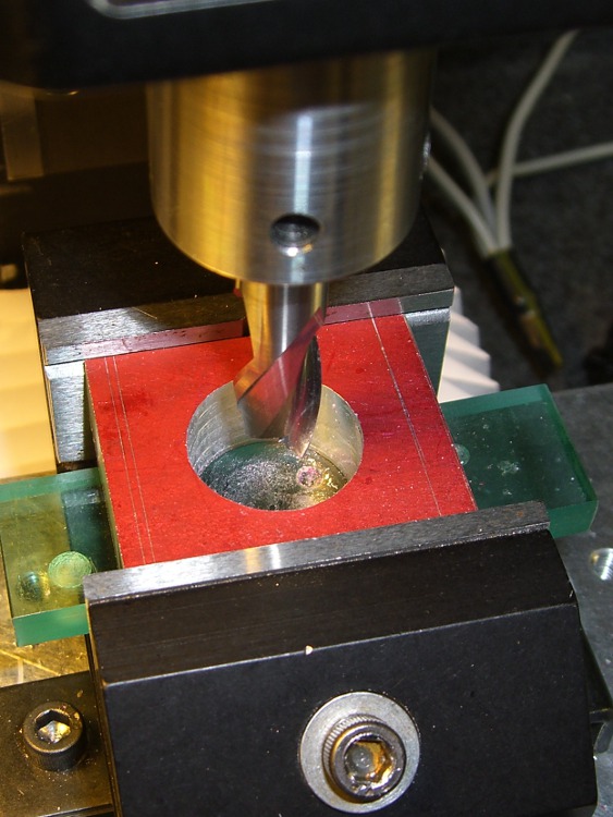
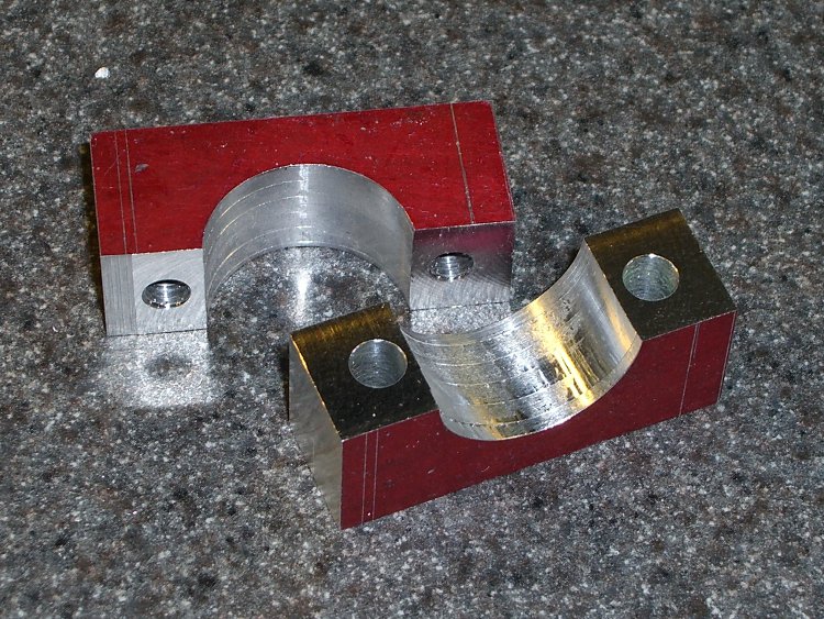
Machining the clamp is straightforward: bandsaw a block of about the right size, square it up in the mill, helix-mill the clamp hole …
Helix-milling the clamp hole
Drill the clearance and tapping holes for the screw, bandsaw it in half, clean up the cut edges …
Finished clamp parts
Obviously, I didn’t put those nice bevels on the front side.
Both previous water bottle holders required a spreader plate between the clamp screws and the holder’s screws, but this time the holder had a nice aluminum plate all by itself. It just fit on the Sherline and a bit of manual CNC center-drilled the curved plate and poked a jobber-length drill through the holes …
Drilling holder for clamp screws
And then it fit perfectly on the bike …
Mounted holder
A side view …
Mounted holder – side view
Now, to find a wedge pack big enough for the HT and small enough to fit in the holder!