The Smell of Molten Projects in the Morning

Ed Nisley's Blog: Shop notes, electronics, firmware, machinery, 3D printing, laser cuttery, and curiosities. Contents: 100% human thinking, 0% AI slop.

Tag: Sewing

Fabric arts and machines

  • Solar-Flattening Fiskars Cutting Mats

    Solar-Flattening Fiskars Cutting Mats

    Fiskars cutting mats must lie flat on the table to be of any use, but they’re remarkably sensitive to warping due to localized temperature variations; a hot cup of tea can wreak a remarkable amount of damage. Suggestions from the InterWebs generally involve a clothes iron, temperature tweaks, overnight cooling, and unpredictable results.
    Given that the mats are large polypropylene sheets, I figured applying moderate heat to the entire mat while it’s compressed between two flat plates would work better:

    Fiskars cutting mat - solar flattening
    Fiskars cutting mat – solar flattening

    That’s one of Mary’s 36×24 mats atop an MDF sheet (with pictures of wood laminated to both sides), under a 7/32 inch = 5.6 mm sheet of non-tempered glass, with a maple shelf supporting the last two inches of the unwarped edge, all sitting on the driveway in full sun.

    The first attempt started too late in the afternoon for good heating and, after a few hours, had only slightly reduced the warp. Laying it out the next morning got the mat up to about 110 °F = 43 °C around noon and the warp was completely gone by evening.

    I don’t trust the IR thermometer’s temperature measurements on glass, but the surrounding MDF and driveway were plenty hot.

    The next sunny day flattened the warp out of 24×18 inch mat on my desk, so success wasn’t a fluke.

    We noticed that the larger mat is now uniformly smaller by about 3/16 inch along the 36 inch width and 1/4 inch over the 24 inch height. It was a tag sale find with unknown provenance and, due to the warp, Mary had been using her other large mat for layout, so we don’t know if this one arrived a little short or if my technique both flattened and shrank it.

    The smaller mat seems unaffected by its similar treatment, so your mileage may vary.

    In any event, a flat mat is much more useful than a warped mat, so we’ll call the operation a success.

  • Knitting Stitch Counters: Material Tests

    Knitting Stitch Counters: Material Tests

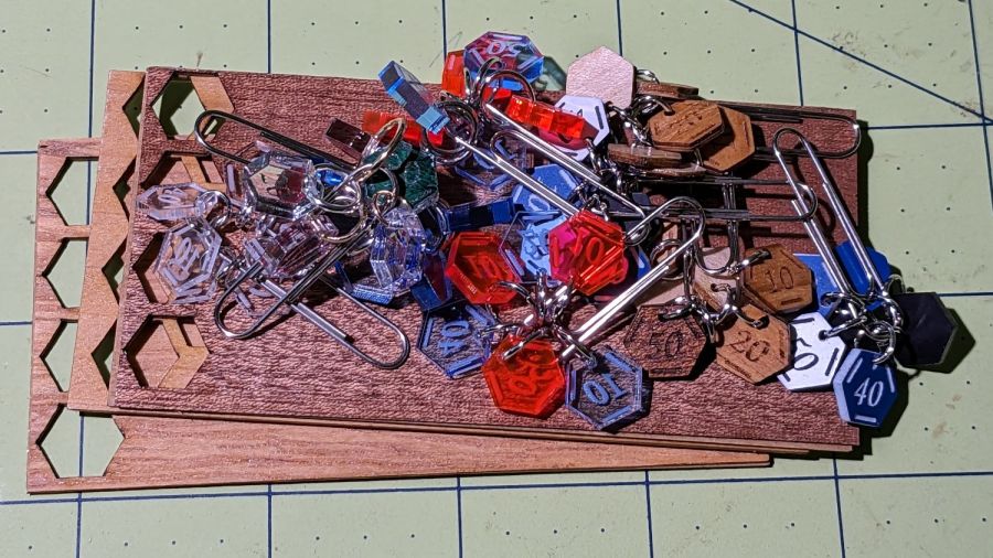
    Our Young Engineer knits during rare moments of downtime and sketched an idea for stitch counters to mark progress between those moments. There being nothing like a new project to take one’s mind off all of one’s previous projects:

    Stitch Counters - overview
    Stitch Counters – overview

    These are more along the lines of feasibility / material tests than finished products, so you’ll see plenty of rough edges.

    Prior to doing this, we agreed that 3 mm material was probably too thick, particularly given the small scale: the hexagons are 10 mm edge-to-edge with a 1.5 mm hole for the jump ring.

    The jump rings are (mostly) 8 mm OD, which may or may not be the right diameter for all possible knitting needles.

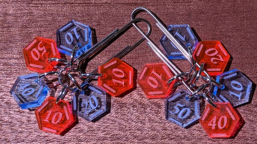
    The count sequence goes 10 20 10 40 50 10 with alternating colors:

    Stitch Counters - red and blue
    Stitch Counters – red and blue

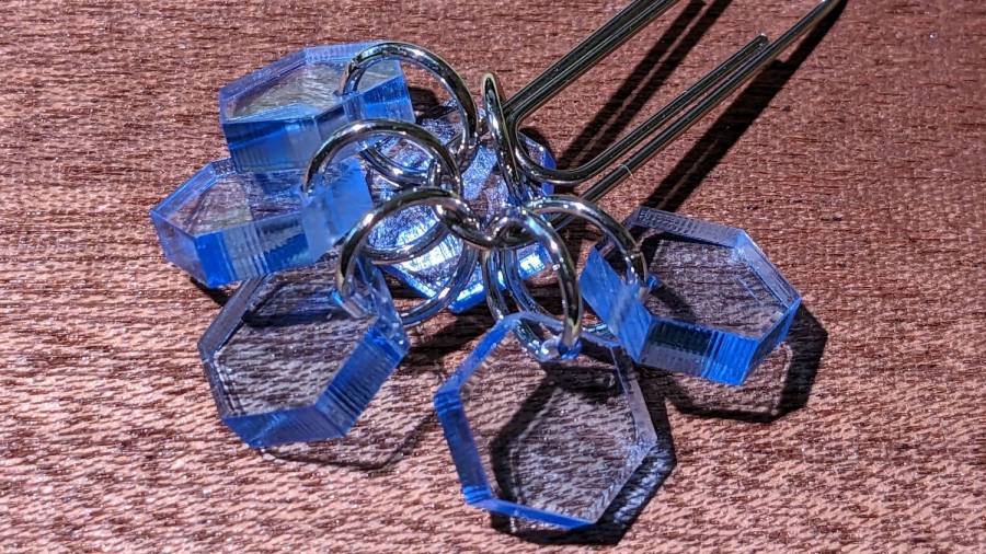
    Those came from 3 mm red and blue transparent acrylic, looking entirely too much like candy. Cutting two identical layouts from two different materials, then swapping a few counters, gives me two related-but-different sets. This idea is also subject to revision.

    I like the set of 3 mm acrylic mirror counters colored with Sharpie:

    Stitch Counters - mirror
    Stitch Counters – mirror

    Alas, the unprotected mirror backing won’t survive long in the real world and Sharpie ink tends to stress-crack the acrylic. Bonding a thin colored sheet / gel filter to the back with an adhesive sheet in between would work, although I don’t look forward to the fiddly alignment. Bonus: sticky edges are a nonstarter in this application.

    A setup error produced a set of unmarked counters that might still come in handy for something:

    PXL_20230507_150124595 - Stitch Counters - blue blank
    PXL_20230507_150124595 – Stitch Counters – blue blank

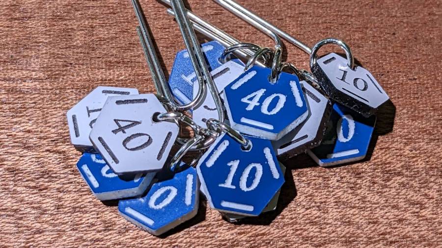
    Trolase acrylic 1/16 inch = 1.5 mm sheets produce the most visible legends, in a relentlessly industrial sort of way:

    Stitch Counters - Trolase
    Stitch Counters – Trolase

    Those have a single thin layer atop a white or black base sheet, but three-layer 1.5 mm Trolase sheets with matching top and bottom colors (cladding on a white core) would look better.

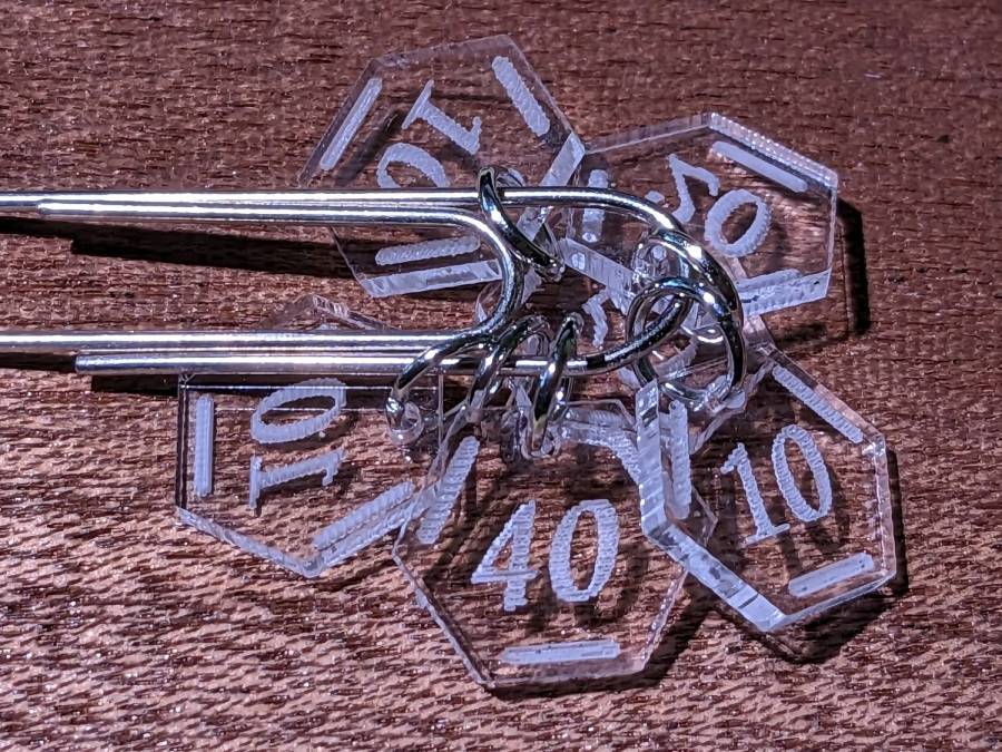
    If you can’t decide on a color, go clear:

    Stitch Counters - clear
    Stitch Counters – clear

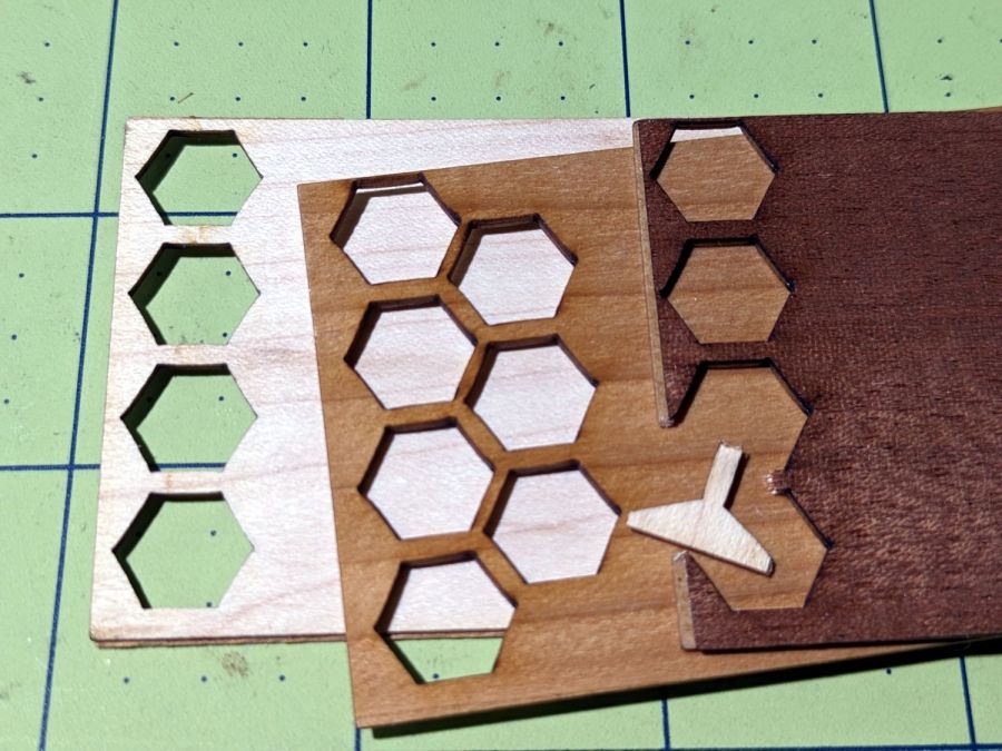
    All of those appear on a background of some thin DIY plywood:

    Stitch Counters - veneer plywood sheets
    Stitch Counters – veneer plywood sheets

    The bottom sheet is very pale veneer that came with a layer of genuine 3M 468 transfer tape with 200MP adhesive. I stuck three different veneers on three 100×50 mm rectangles of the stuff to make 1.5 mm thick “plywood”. The adhesive sheet provides lateral strength, not the wood fibers, so it’s not quite as easy to tear as the broken fragment would suggest.

    The results look passable, although there’s room for improvement:

    Stitch Counters - veneer plywood
    Stitch Counters – veneer plywood

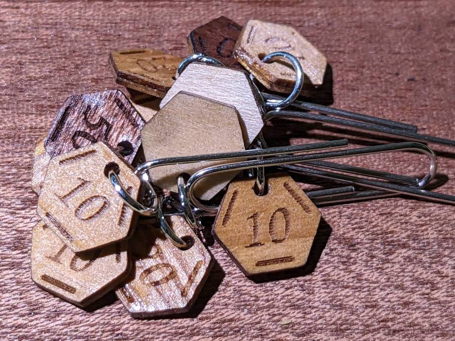
    After engraving & cutting, I slathered them with clear polyurethane finish and hung them up to dry:

    Stitch Counters - wood finish curing
    Stitch Counters – wood finish curing

    I like the effect, but using the pale veneer for the bottom layer made them look identical from that side. Worse, two of the three top layer veneers had nearly identical colors (one has more grain) after the finish cured.

    More thought seems in order, but at least I’ve explored some of the solution space.

  • Bobbin Storage Trays

    Bobbin Storage Trays

    Long ago, I gave Mary a box of 100 empty bobbins for her Kenmore 158 sewing machine, with the intent she would never again have to unwind a bobbin to put new thread on it. This worked so well I did the same thing for her Juki, with the result she needed somewhere to store all those filled bobbins.

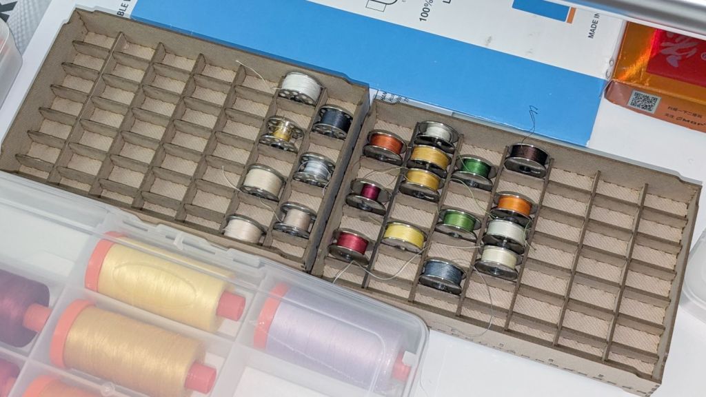
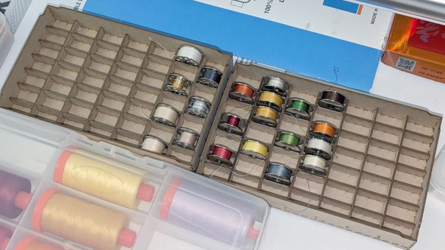
    Her work table has a shallow drawer, so we tried this out:

    Bobbin Storage Case - installed
    Bobbin Storage Case – installed

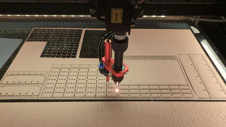
    They’re a matched set cut from 1.5 mm TroCraft Eco:

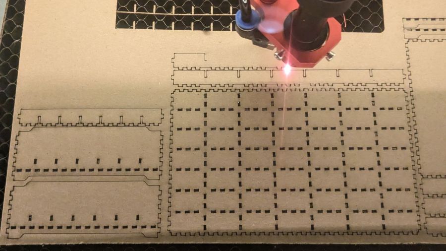
    Bobbin Storage Case - cutting overview
    Bobbin Storage Case – cutting overview

    Watching all those little rectangles fall out just never gets old:

    Bobbin Storage Case - cutting detail
    Bobbin Storage Case – cutting detail

    I ran off a test tray in ordinary chipboard that works just as well, but lacks the pleasant appearance and feel of the TroCraft. Clear 1.5 mm acrylic would probably work, at the cost of requring a much neater glue job where the dividers meet the walls.

    The spacing is a bit tight to pluck a bobbin from its slot between two others, but now she has enough space to arrange them as needed, with empty spaces around the most-used colors. I offered to carpet the drawer with bobbin trays, but she suggested waiting until these fill up.

    The well-stuffed URL specifying the tray:

    http://festi.info/boxes.py/TypeTray?FingerJoint_angle=90.0&FingerJoint_style=rectangular&FingerJoint_surroundingspaces=0.5&FingerJoint_bottom_lip=0.0&FingerJoint_edge_width=1.0&FingerJoint_extra_length=0.0&FingerJoint_finger=2.0&FingerJoint_play=0.0&FingerJoint_space=2.0&FingerJoint_width=1.0&Stackable_angle=60&Stackable_bottom_stabilizers=0.0&Stackable_height=2.0&Stackable_holedistance=2.0&Stackable_width=4.0&Hinge_grip_percentage=0&Hinge_outset=0&Hinge_pinwidth=0.5&Hinge_style=outset&Hinge_axle=2.0&Hinge_grip_length=0&Hinge_hingestrength=1&CabinetHinge_bore=3.2&CabinetHinge_eyes_per_hinge=5&CabinetHinge_hinges=2&CabinetHinge_style=inside&CabinetHinge_eye=1.5&CabinetHinge_play=0.05&CabinetHinge_spacing=2.0&Lid_angle=90.0&Lid_hole_width=0&Lid_second_pin=0&Lid_second_pin=1&Lid_spring=both&Lid_style=rectangular&Lid_surroundingspaces=2.0&Lid_bottom_lip=0.0&Lid_edge_width=1.0&Lid_extra_length=0.0&Lid_finger=3.0&Lid_play=0.05&Lid_space=2.0&Lid_width=1.0&Click_angle=5.0&Click_bottom_radius=0.1&Click_depth=3.0&RoundedTriangleEdge_height=50.0&RoundedTriangleEdge_r_hole=2.0&RoundedTriangleEdge_radius=30.0&RoundedTriangleEdge_outset=1.0&Mounting_d_head=6.5&Mounting_d_shaft=3.0&Mounting_margin=0.125&Mounting_num=2&Mounting_side=back&Mounting_style=straight+edge%2C+within&HandleEdge_height=20.0&HandleEdge_hole_height=75.0&HandleEdge_hole_width=40%3A40&HandleEdge_on_sides=0&HandleEdge_on_sides=1&HandleEdge_radius=10.0&HandleEdge_outset=1.0&sx=21*7&sy=12*7&h=20.0&hi=10.0&outside=0&bottom_edge=s&top_edge=S&back_height=0.0&radius=0.0&gripheight=30&gripwidth=00&handle=0&thickness=1.65&format=lbrn2&tabs=0&debug=0&labels=0&reference=00&inner_corners=corner&burn=0.04

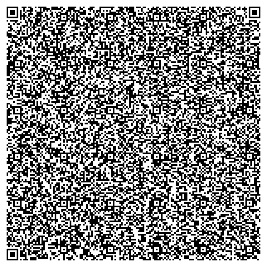
    Which can now be specified as the biggest QR code I’ve ever seen:

    Bobbin Tray - TroCraft Eco QR code
    Bobbin Tray – TroCraft Eco QR code

    That makes my eyes hurt …

  • Laser Engraved Fabric

    Laser Engraved Fabric

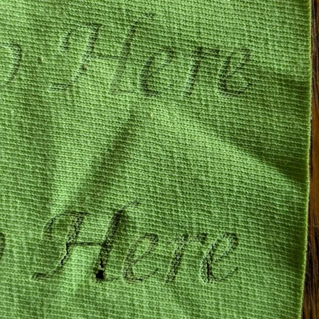
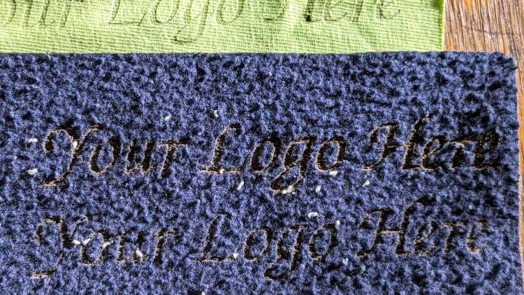
    This is more along the lines of searing the fuzz, rather than actual engraving:

    Laser Engraved Fabric - cotton knit
    Laser Engraved Fabric – cotton knit

    The top row is 15% power at 400 mm/s, the bottom is 25% power, and the fabric was a cotton t-shirt from the Box o’ Shop Wipes.

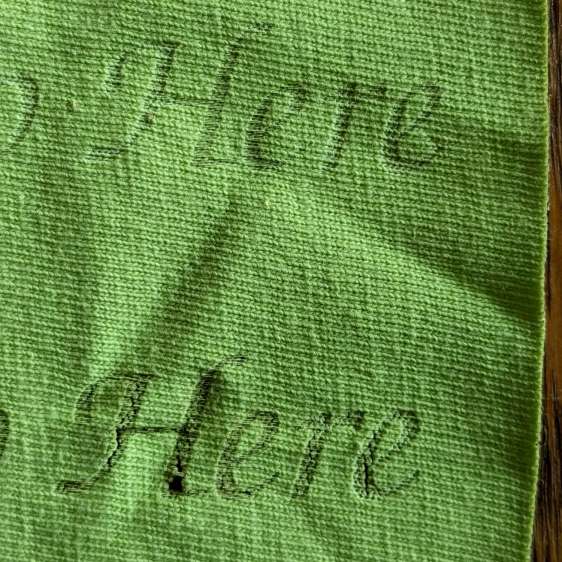
    Applying the higher power to the inside of sweatpants fabric, whatever that might be:

    Laser Engraved Fabric - sweatpants
    Laser Engraved Fabric – sweatpants

    Both of those were easier to see in the slanting sunlight of a later winter afternoon.

    The best results come from the lowest feasible power applied at the fastest practical speed, with obvious size and complexity limitations.

    I think this will most useful on a removable tag labeling a piece (perhaps cut from a larger pattern), rather than branding the piece itself.

  • Tailor’s Clapper: 3D Printed Finger Grips

    Tailor’s Clapper: 3D Printed Finger Grips

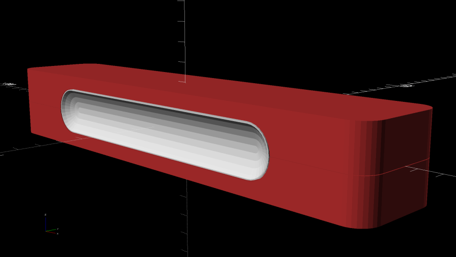
    With the pockets milled into the oak blocks, the next step is to insert a pair of comfy 3D printed finger grips:

    Ironing weight - prototype grip
    Ironing weight – prototype grip

    Getting comfy required a bank shot off the familiar chord equation to find the radius of a much larger circle producing the proper depth between the known width. The recess then comes from subtracting a hotdog from a lozenge exactly filling the wood pocket.

    Ironing Weight Finger Grip - recess chord
    Ironing Weight Finger Grip – recess chord

    A pair of grips takes just under two hours to print while requiring no attention, which I vastly prefer to tending the Sherline.

    The wood pocket is 7 mm deep and the grips stand 6.5 mm tall, leaving just enough room for three blobs of acrylic adhesive to hold them together. After squishing the grips into their pockets, a pair of right angles aligned everything while the adhesive cured:

    Ironing weight - grip adhesive curing
    Ironing weight – grip adhesive curing

    Mary asked for a longer weight for a place mat project, with a slightly narrower block to compensate for the additional length:

    Ironing weight - seam ironing B
    Ironing weight – seam ironing B

    The grip and pocket were the same size, so it was just a matter of tweaking the block size and cutting more wood.

    All in all, a quick project with satisfying results!

    The OpenSCAD source code as a GitHub Gist:

    // Oak ironing weight finger grips
    // Ed Nisley KE4ZNU 2023-01
    Layout = "Show"; // [Block,Grip,Show,Build]
    //- Extrusion parameters must match reality!
    /* [Hidden] */
    ThreadThick = 0.25;
    ThreadWidth = 0.40;
    HoleWindage = 0.2;
    Protrusion = 0.1; // make holes end cleanly
    inch = 25.4;
    function IntegerMultiple(Size,Unit) = Unit * ceil(Size / Unit);
    ID = 0;
    OD = 1;
    LENGTH = 2;
    //———-
    // Dimensions
    // Length along X axis
    Block = [250.0,50.0,39.0]; // overall wood block
    BlockRadius = 10.0;
    CornerRadius = 10.0;
    Kerf = 0.2;
    Socket = [160.0,25.0,6.5]; // raw recess into block
    SocketRadius = Socket.y/2;
    echo(Socket=Socket,SocketRadius=SocketRadius);
    WallThick = ThreadWidth; // Thinnest printed wall
    Clearance = 0.5; // between grip and recess
    GripBlock = Socket – [2*Clearance,2*Clearance,Clearance];
    GripBlockRadius = SocketRadius – Clearance;
    echo(GripBlock=GripBlock);
    GripDepth = 5.0; // finger grip recess
    GripRecess = [GripBlock.x – 2*WallThick,GripBlock.y – 2*WallThick,GripDepth];
    GripRecessRadius = GripBlockRadius – WallThick;
    echo(GripRecess=GripRecess,GripRecessRadius=GripRecessRadius);
    GripChordRadius = (pow(GripDepth,2) + pow(GripRecess.y,2)/4) / (2*GripDepth);
    echo(GripChordRadius=GripChordRadius);
    NumSides = 4*8;
    //———-
    // Shapes
    module WoodBlock() {
    difference() {
    hull()
    for (i=[-1,1], j=[-1,1]) // rounded block
    translate([i*(Block.x/2 – BlockRadius),j*(Block.y/2 – BlockRadius),-Block.z/2])
    cylinder(r=BlockRadius,h=Block.z,$fn=NumSides);
    for (j=[-1,1]) // grip socket
    translate([0,j*(Block.y/2 + Protrusion),0])
    rotate([j*90,0,0])
    hull() {
    for (i=[-1,1])
    translate([i*(Socket.x/2 – SocketRadius),(Socket.y/2 – SocketRadius),0])
    cylinder(r=SocketRadius,h=Socket.z + Protrusion,$fn=NumSides);
    }
    cube([2*Block.x,2*Block.y,Kerf],center=true);
    }
    }
    module Grip() {
    difference() {
    hull()
    for (i=[-1,1]) // overall grip block
    translate([i*(GripBlock.x/2 – GripBlockRadius),0,0])
    cylinder(r=GripBlockRadius,h=GripBlock.z,$fn=NumSides);
    hull() {
    for (i=[-1,1]) // grip recess
    translate([i*(GripBlock.x/2 – GripRecessRadius – WallThick),
    0,
    GripChordRadius + GripBlock.z – GripDepth])
    sphere(r=GripChordRadius,$fn=NumSides);
    }
    }
    }
    //———-
    // Build them
    if (Layout == "Block")
    WoodBlock();
    if (Layout == "Grip")
    Grip();
    if (Layout == "Show") {
    color("Brown")
    WoodBlock();
    color("Silver")
    for (j=[-1,1])
    translate([0,j*(Block.y/2 – GripBlock.z),0])
    rotate([j*-90,0,0])
    Grip();
    }
    if (Layout == "Build") {
    for (i=[-1,1])
    translate([i*(Block.y/2 – GripBlock.z),0,0])
    rotate([0,0,90])
    Grip();
    }

  • Tailor’s Clapper: CNC Pocketing

    Tailor’s Clapper: CNC Pocketing

    Separating the interior contour of the finger grip from its overall shape let me reduce the woodworking to a simple pocketing operation:

    Ironing Weight Finger Grip
    Ironing Weight Finger Grip

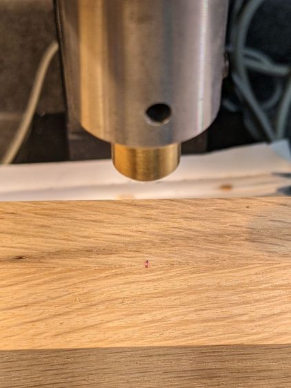
    Start by aligning the finished block to put the joint between the pieces parallel to the X axis, then touch off at the center:

    Ironing Weight - alignment
    Ironing Weight – alignment

    A pair of clamps screwed to the tooling plate act as fixtures to align the block when it’s flipped over to mill the other pocket.

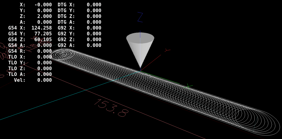
    Just to see how it worked, I set up a GCMC program to produce a trochoidal milling pattern using the sample program:

    Tailors Clapper - Pocket Milling Path
    Tailors Clapper – Pocket Milling Path

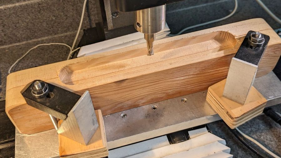
    Now, most folks would say the Sherline lacks enough speed and stiffness for trochoidal milling:

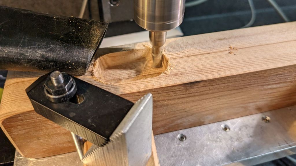
    Ironing weight - trochoidal milling
    Ironing weight – trochoidal milling

    Aaaand I would agree with them: chugging along at 24 in/min = 600 mm/min doesn’t put the 10 k RPM spindle speed to good use. Fortunately, oak doesn’t require much in the way of machine stiffness and the trochoid path does ensure good chip clearance, so there’s that.

    If I had to do a lot of trochoid milling, I’d tweak the GCMC sample code to short-cut the return path across the circle diameter, rather than air-cut the last half of every circumference.

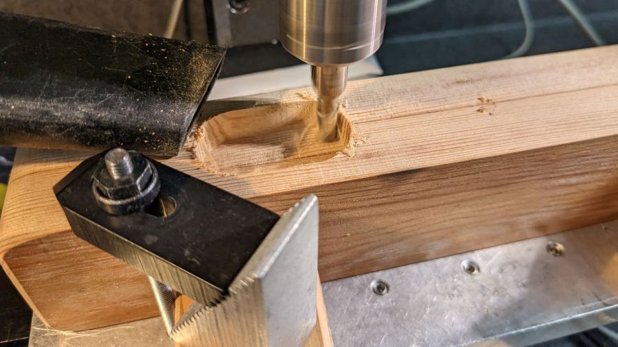
    The code starts by emptying a circular pocket so the trochoid path begins in clear air, rather than trenching into solid wood.

    Eventually it finishes the pocket:

    Ironing weight - grip pocket
    Ironing weight – grip pocket

    After the trochoid finishes, one climb-milling pass around the perimeter clears the little ripple between each trochoid orbit.

    Flip it over, clamp it down, touch off the middle, and do it all again.

    The next step is filling those pockets with a pair of comfy grips.

    The GCMC source code as a GitHub Gist:

    // Ironing weight pocketing
    // Ed Nisley KE4ZNU – 2023-01
    //—–
    // Library routines
    include("/opt/gcmc/example/cc_hole.inc.gcmc");
    include("varcs.inc.gcmc");
    include("tracepath_comp.inc.gcmc");
    include("trochoidal.inc.gcmc");
    /*
    include("tracepath.inc.gcmc");
    include("engrave.inc.gcmc");
    */
    //—–
    // Useful constants
    SafeZ = 10.0mm; // above all obstructions
    TravelZ = 2.0mm; // within engraving / milling area
    BlockHome = [0.0mm,0.0mm,TravelZ]; // Origin on surface at center of pocket
    FALSE = 0;
    TRUE = !FALSE;
    //—–
    // Overall values
    Socket = [160.0mm,25.0mm,7.0mm]; // raw grip recess into block
    RoundEnds = TRUE; // TRUE for smooth rounded endcaps
    SocketRadius = RoundEnds ? Socket.y/2 : 10.0mm;
    comment("SocketRadius: ",SocketRadius);
    CutterDia = 6.32mm – 0.15; // actual cutter diameter – windage
    MillStep = 0.25 * CutterDia; // stepover in XY plane
    comment("CutterDia: ",CutterDia," MillStep: ",MillStep);
    MillClean = MillStep/2;
    PlungeSpeed = 150.0mm; // cutter Z plunge into work
    MillSpeed = 600.0mm; // XY speed
    if (CutterDia > SocketRadius) {
    error("Cutter too large for corner radius");
    }
    CornerOC = head(Socket,2) – 2*[SocketRadius,SocketRadius];
    comment("CornerOC: ",CornerOC);
    Corners = RoundEnds ? // rear left CCW around slot
    {-CornerOC/2, CornerOC/2} :
    {[-CornerOC.x,CornerOC.y]/2, [-CornerOC.x,-CornerOC.y]/2, [CornerOC.x,-CornerOC.y]/2, CornerOC/2};
    comment("Corners: ", Corners);
    if (RoundEnds) {
    SlotPerimeter = {[0.0mm,Socket.y/2,-Socket.z]}; // entry point at center rear
    SlotPerimeter += {Corners[0] + [0.0mm,SocketRadius]};
    SlotPerimeter += varc_ccw([-SocketRadius,-SocketRadius],SocketRadius) + SlotPerimeter[-1];
    SlotPerimeter += varc_ccw([+SocketRadius,-SocketRadius],SocketRadius) + (Corners[0] + [-SocketRadius,0.0mm]);
    SlotPerimeter += {Corners[1] + [0.0mm,-SocketRadius]}; // across front
    SlotPerimeter += varc_ccw([+SocketRadius,+SocketRadius],SocketRadius) + SlotPerimeter[-1];
    SlotPerimeter += varc_ccw([-SocketRadius,+SocketRadius],SocketRadius) + (Corners[1] + [+SocketRadius,0.0mm]);
    }
    else {
    SlotPerimeter = {[0.0mm,Socket.y/2,-Socket.z]}; // entry point at center rear
    SlotPerimeter += {Corners[0] + [0.0mm,SocketRadius]};
    SlotPerimeter += varc_ccw([-SocketRadius,-SocketRadius],SocketRadius) + SlotPerimeter[-1];
    SlotPerimeter += {Corners[1] + [-SocketRadius,0.0mm]};
    SlotPerimeter += varc_ccw([+SocketRadius,-SocketRadius],SocketRadius) + SlotPerimeter[-1];
    SlotPerimeter += {Corners[2] + [0.0mm,-SocketRadius]}; // across front
    SlotPerimeter += varc_ccw([SocketRadius,SocketRadius],SocketRadius) + SlotPerimeter[-1];
    SlotPerimeter += {Corners[3] + [SocketRadius,0.0mm]};
    SlotPerimeter += varc_ccw([-SocketRadius,SocketRadius],SocketRadius) + SlotPerimeter[-1];
    }
    //— Begin cutting
    goto([-,-,TravelZ]);
    goto(BlockHome);
    if (!RoundEnds) { // clear corners outward of main pocket
    foreach(Corners; xy) {
    comment("Plunge corner at: ",xy);
    feedrate(PlungeSpeed);
    goto(xy);
    move([-,-,-Socket.z]);
    comment(" pocket");
    feedrate(MillSpeed);
    cc_hole(xy,(SocketRadius – MillClean),CutterDia/2,MillStep,-Socket.z);
    goto([-,-,TravelZ]);
    comment(" done!");
    }
    }
    comment("Open slot");
    TrochRadius = (Socket.y – CutterDia)/2 – MillClean;
    TrochPath = {[-(Socket.x/2 – TrochRadius – CutterDia/2 – MillStep),TrochRadius],
    [ (Socket.x/2 – TrochRadius – CutterDia/2 – MillStep),TrochRadius]};
    comment(" clear landing zone");
    xy = [TrochPath[0].x,0.0mm];
    feedrate(PlungeSpeed);
    goto(xy);
    move([-,-,-Socket.z]);
    feedrate(MillSpeed);
    cc_hole(xy,Socket.y/2 – MillClean,CutterDia/2,MillStep,-Socket.z);
    goto([-,-,TravelZ]);
    comment(" trochoid pocket milling");
    feedrate(MillSpeed);
    trochoid_move(TrochPath[0],TrochPath[1],
    -Socket.z, TrochRadius, MillStep);
    goto([-,-,TravelZ]);
    comment("Clean slot perimeter");
    feedrate(MillSpeed);
    goto([-,-,-Socket.z]);
    tracepath_comp(SlotPerimeter,CutterDia/2,TPC_CLOSED + TPC_LEFT + TPC_ARCIN + TPC_ARCOUT);
    goto([-,-,TravelZ]);
    goto(BlockHome);
    #!/bin/bash
    # Ironing weight finger grip pocketing
    # Ed Nisley KE4ZNU – 2023-01
    Flags='-P 4 –pedantic' # quote to avoid leading hyphen gotcha
    # Set these to match your file layout
    LibPath='/opt/gcmc/library'
    Prolog='prolog.gcmc'
    Epilog='epilog.gcmc'
    #—–
    gcmc $Flags \
    –include "$LibPath" –prologue "$Prolog" –epilogue "$Epilog" \
    "Ironing weight grip pocket.gcmc" > "Grip pocket.ngc"
    view raw pocket.sh hosted with ❤ by GitHub

  • Tailor’s Clapper: Laser-Cut Woodwork

    Tailor’s Clapper: Laser-Cut Woodwork

    Creating the rounded-rectangle shape of a tailor’s clapper in LightBurn, then cutting it out, doesn’t pose much of a challenge:

    Ironing weight - cutting oak plank
    Ironing weight – cutting oak plank

    That was a prototype cut from an oak plank with some fairly obvious splits. It turned out OK, but ¾ inch oak is obviously right at the limit of my 60 W laser’s abilities:

    Ironing weight - laser cut edges
    Ironing weight – laser cut edges

    The “production” clappers came from a nicer plank that was just barely long enough:

    Ironing weight - laser cuts - top
    Ironing weight – laser cuts – top

    The cut, at 2 mm/s and 70% power, just barely penetrates the plank:

    Ironing weight - laser cuts - bottom
    Ironing weight – laser cuts – bottom

    Unlike the top picture, I put the plank on the knife-edge supports, resulting in the small charred lines perpendicular to the cut.

    The edges came out thoroughly charred:

    Ironing weight - laser cuts - edges
    Ironing weight – laser cuts – edges

    Spread yellow wood glue smoothly on one piece, stick another to it, then align and clamp:

    Ironing weight - clamping
    Ironing weight – clamping

    I offset the cut 1 mm outside the nominal shape to allow Mr Belt Sander to remove the char while reducing the block to size. Obviously, there is no real tolerance, other than that it must fit Mary’s hand, and they all came out nice and straight.

    Some of the char seems embedded deep in the wood grain and leaves a dark mark despite removing the extra millimeter:

    Ironing weight - seam ironing B
    Ironing weight – seam ironing B

    Contrary to what I feared, the characteristic wood-stove odor dissipated after a day or two: they’re entirely inoffensive. Which was fortunate, as the slightest odor would cause them to fail incoming inspection.

    The longer weight on the far left came from a plank with a conspicuous knot on one end. The stress from supporting that branch while the tree grew apparently made the wood much denser, as the same 2 mm/s 70% cut setting barely made it halfway through the plank. I finished the job by cutting the outline with Tiny Bandsaw™, which didn’t proceed any faster than the laser and left a much less uniform path for Mr Belt Sander.

    I’d definitely consider making any future tailor’s clappers by laminating three half-inch oak planks that would be much easier to cut, but my woodpile doesn’t have anything like that.

    The wood remains unfinished, as part of its job is to absorb moisture from steam-ironed fabric (which is not happening in the photo). Applying stains / sealers / finishes would definitely improve the wood’s appearance, but wreck its performance. Around here, function always outweighs form.