Ed Nisley's Blog: Shop notes, electronics, firmware, machinery, 3D printing, laser cuttery, and curiosities. Contents: 100% human thinking, 0% AI slop.
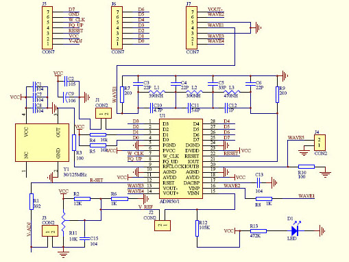
… with any of the doc for the generic AD8950/51 DDS modules you’ll find out on the Interwebs. This snippet from the seller’s schematic will suffice:
AD9850 module schematic – cropped
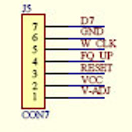
Here’s a closer look at the 2×7 header in the upper left corner:
AD9850 module schematic – J5 detail
Don’t blame me for the blur, the schematic is a JPG.
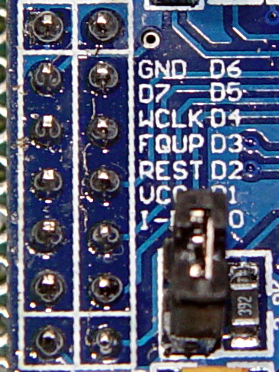
Compared it with the board in hand:
AD9850 DDS Module – swapped GND D7 pins – detail
Yup, the D7 and GND pins are reversed.
Some careful probing showed the silkscreen is correct: the pins are, in fact, correctly labeled.
Should you be laying out a PCB in the expectation of using any DDS module from the lowest-price supplier, remember this high truth: Hell hath no fury like that of an unjustified assumption.
Fortunately, I’m hand-wiring the circuit and caught it prior to the smoke test.
Adding a 56 nF cap across the C6 terminals (just above the AD8310) lowered the VBW to about 1 kHz:
AD8310 Log Amp module – VBW rolloff cap
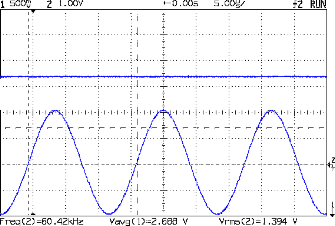
Which flattened that sucker right out:
AD8310 – 1 kHz VBW cap – 60 kHz 1.394 V
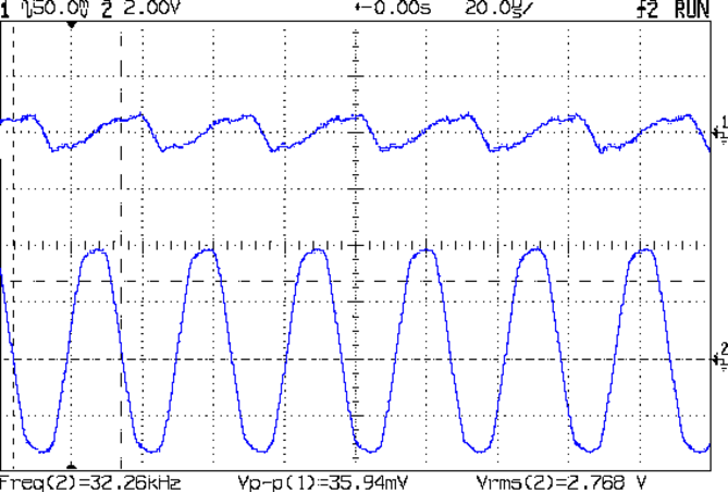
The ripple for an absurdly high amplitude 32 kHz signal amounts to 36 mV:
AD8310 – 1 kHz VBW cap – 32 kHz – VBW ripple
Firing the tracking generator into the input with a frequency sweep from 100 kHz to 250 MHz shows the low end looks much better:
AD8310 – 1 kHz VBW cap – 100 kHz 250 MHz – 0 dB atten
There’s a slight droop across the sweep that might amount to 50 mV = 2 dB, which I’m inclined to not worry about in this context.
Applying the attenuators once again produces a scale factor of 23.5 mV/dB across 30 dB of RF, but this time the 60 kHz output makes sense, too.
Using the typical output curve from AN-691, that 2.0 V output corresponds to -13 dBm, which sounds about right for the tracking generator (which might really be -10 dBm).
I must calibrate the log amp output to find the actual intercept point (nominally -95 dBm, but could range from -86 to -102) at 60 kHz. The intercept is the extrapolated RF input producing 0 V out, which then acts as an offset for the voltage-to-dBm calculation; you start by finding the slope of the voltage vs. dBm line at some convenient power levels, then solve for dBm with V=0.
So a cheap AD8310 Log Amp module from eBay can work in the LF band, after you rearrange the input circuitry and tweak the chip’s filters. At least now I have a better understanding of what’s going on …
Given the intended LF crystal-measurement application, a hulking 51 Ω metal film resistor sprawled across the ground plane will work just fine. All three ceramic caps measure a bit under 1 µF; I intended to solder the input caps atop the existing 10 nF caps, but that didn’t work out well at all.
I should harvest the InLo SMA connector to prevent anyone from mistaking it for an actual input.
With that in place, the log amp output makes more sense:
AD8310 – modified – 100 kHz 150 MHz – 0 dB atten
That trace tops out at 150 MHz, not the previous 500 MHz, but now the response is flat all the way out. The log amp generates plenty of hash when the tracking generator isn’t producing a valid signal.
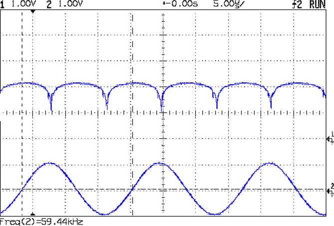
The 60 kHz response looks different:
AD8310 – modified – 60 kHz 1Vpp
So it’s really the log amp response to the absolute value of the sine wave (or, more accurately, to the sine wave re-zeroed around Vcc/2), with minimum output at the input’s zero crossings. At 500 mV/div, the log amp says the input varies by 42 dB = 1000 mV/(24 mV/dB), which might actually be about right for a zero-crossing (or zero-approaching absolute value of a) signal; logarithms don’t deal well with zeros.
The AD8310 datasheet and AN-691 suggest the 2.5 V output corresponds to +10 dBm = 12.5 Vrms input, which flat-out isn’t the case. However, the actual 500 mVpeak = 350 mVrms input is 2.5 mW = +4 dBm, so maybe it’s within spitting distance of being right.
AN-691 recommends 10 µF input caps for “low frequency” use, showing results down to 20 Hz; 1 µF seems to get the circuit close enough to the goal for use near 60 kHz.
It also recommends a cap on the BFIN pin (pin 6) to reduce the output stage bandwidth = “video bandwidth” and improve the overall accuracy, which remains to be done. The datasheet suggests rolling VBW off at 1/10 the minimum input frequency, which would be around 3 kHz for use with 32.768 kHz crystals. The equation, with reference to the internal 3 kΩ bias resistor:
CFILT = 1/(2π 3 kΩ VBW) – 2.1 pF = 18 nF
For a bit more margin, 1 kHz would require 56-ish nF.
The PCB has a convenient pair of pads labeled C6 for that capacitor. This may require protracted rummaging in the SMD capacitor stash.
Rolling off the VBW should reduce the hash on the 100 kHz end of the frequency sweep and filter the 60 kHz response down to pretty much a DC level.
Applying the 10 dB and 20 dB SMA attenuators to the input from the tracking generator and recording the log amp output voltage produces this useful table:
AD8310 Log Amp – mods and log response
With the terminating resistor on the correct side of the input caps, the log amp seems to be working the way it should, with an output varying a bit under the nominal 24-ish mV/dB over a 30 dB range.
We need caps! Lots of caps!
A quick search with the obvious keywords suggests nobody else has noticed how these modules work over a reasonable bandwidth. Maybe I’m the first person to use them in the LF band?
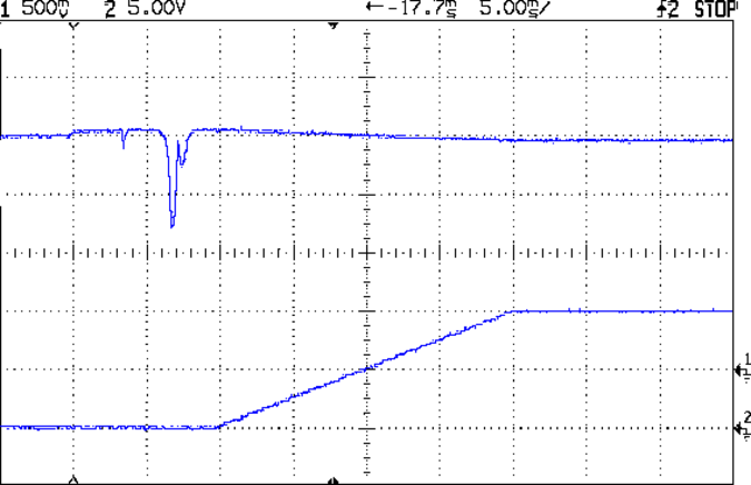
Firing the HP 8591 tracking generator into the InHi SMA, terminating InLo (not shown above, for reasons you’ll see below), connecting the Out SMA to the scope’s Trace 1, and the spectrum analyzer’s sweep output to Trace 2 produced an oddity:
AD8310 Log Amp – 100 kHz 500 MHz
The upward-sloping ramp (lower trace) shows the HP 8591’s horizontal sweep, with the tracking generator tuning from 100 kHz to 500 MHz during the 20 ms sweep. The log amp output (upper trace) drops more-or-less linearly with increasing frequency, which seems odd. The tracking generator signal should be pretty much level and the log amp’s output should be more-or-less flat.
My oscilloscope tops out at 150 MHz. The displayed RF is down by 3 dB = 0.6 div at 1.5 division = 190 MHz into the sweep:
AD8310 Log Amp – 100 kHz 500 MHz – RF 50 ohm term
However, the RF looks pretty much flat up to 125 MHz and it’s still visible beyond 400 MHz, so I think the tracking generator is doing what it’s supposed to. If the RF were decreasing, then the trace would look different, methinks.
The response to a 60 kHz sine wave doesn’t look quite right:
AD8310 Log Amp – 60 kHz 1 Vpk
Eyeballometrically, it might be a log response to the absolute value of the derivative: kinda flat on the ups-and-downs, kinda zero-ish at the tops-and-bottoms. Or maybe it’s the log response to a phase-shifted version of the input, with the lows corresponding to the zero crossings.
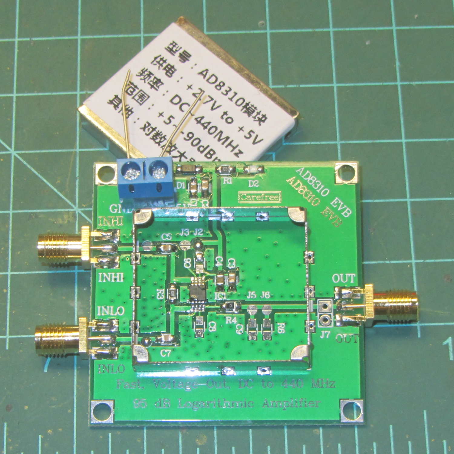
Documentation for the circuit seems nonexistent, because eBay. Fortunately, one can pop the top to reveal the straightforward PCB layout:
AD8310 Log Amp module – uncovered
A closer look:
AD8310 Log Amp module – PCB detail
A capacitance meter says input capacitors C5 and C7 are both 10 nF.
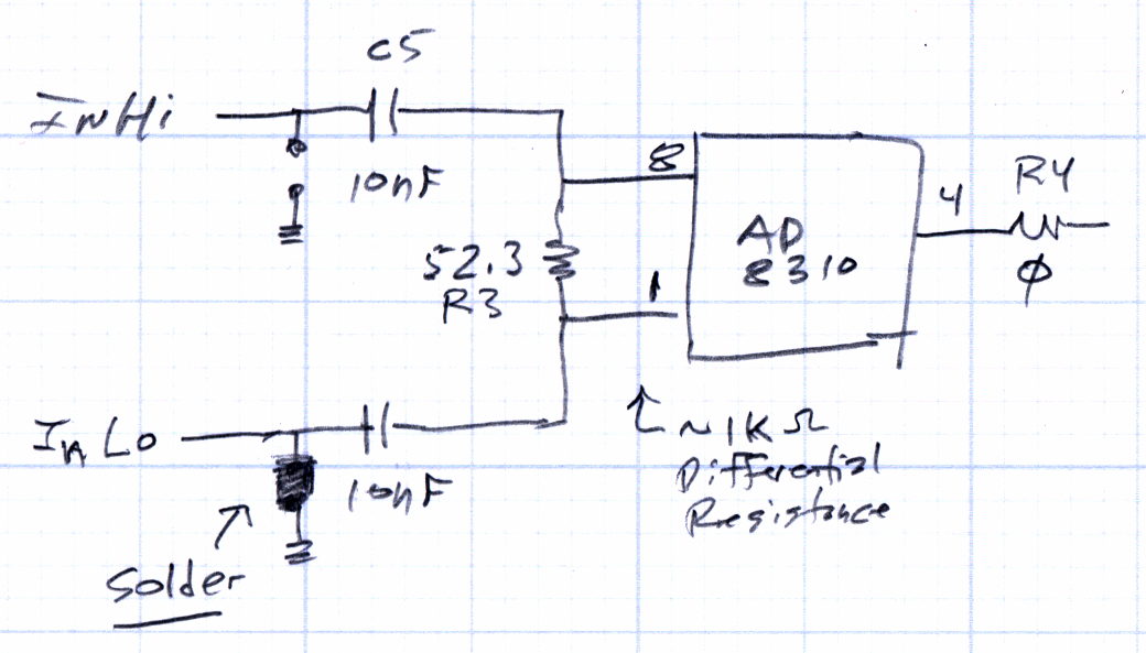
A sketch of the circuitry:
AD8310 Log Amp module – input circuit
The datasheet puts the terminating resistor on the other side of the input caps, where it surely belongs:
AD8310 Datasheet – Basic Connections diagram
Achtung: the solder blob just to the left of C7 grounds the signal pin on the InLo SMA. Don’t connect anything to InLo which might take offense at having its output shorted to ground; the SMA terminator I used had no effect whatsoever.
The AD8310 chip (assuming that’s what it really is) has a differential input resistance = 1 kΩ and capacitance = 1.4 pF in parallel with R3, the 52.3 Ω terminating resistor, making the net resistance just under 50 Ω.
At 60 kHz, the input caps have a reactance of 270 Ω apiece, which means the “terminating” resistor is maybe 10% of the mostly capacitive input impedance seen at the InHi connector. That means the AD8310 inputs see maybe 10% of the input signal.
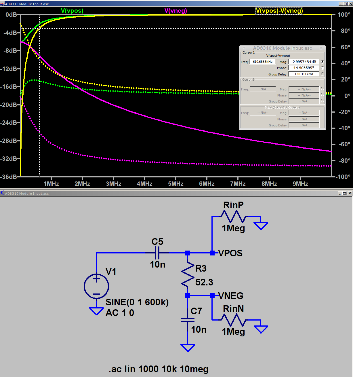
In fact, if you regard those three parts as an RC high pass filter and merge the caps into a single 5 nF unit, it rolls off at 620 kHz = 1/(2π · 52 · 5 pF). Obviously, it’ll be a fine differentiator at 1/10 the breakpoint frequency.
A simulation shows it in action (clicky for more dots):
AD8310 Log Amp module – input circuit simulation
The two 1 MΩ resistors provide a balanced DC path-to-ground for R3 to keep the simulator happy.
The (+) input tends toward 0 dB as C5 tends toward a short, the (-) input tends toward ground as C7 does likewise, but their difference isn’t a constant value. Seeing as how a log amp should respond to small differences, methinks it’s hard at work.
The AD8310 data sheet says the scale factor is about 24 mV/dB between 10 MHz and 200 MHz, with no frequency dependence worth mentioning. Eyeballometrically, the output has a 240 mV = 10 dB straight-line decrease over the entire frequency range of that scope shot. It drops by 220 mV = 9.2 dB in the decade from 50 to 500 MHz, half of the 20 dB you’d expect from a first-order filter response.
The AD8310 has an internal 2 MHz high pass feedback loop to suppress low frequency input offset voltages. The doc recommends a 1 µF cap from OLFT to ground for frequencies down in the low audio range. One might solder the cap across the convenient pads labeled C8 below the chip.
Rearranging the input circuitry seems in order:
Move R3 outside C5 and C7, per the datasheet
Increase C5 and C7 to 1 µF -ish
Add 100nF – 1 µF bypass cap at C8
I have the uneasy feeling I’m overlooking something obvious …
The BigNumber library wraps the bc arbitrary precision calculator into a set of Arduino routines that seem like a reasonable basis for DDS calculations requiring more than the half-dozen digits of a floating point number or the limited range of scaled fixed point numbers tucked into an long int.
This file contains hidden or bidirectional Unicode text that may be interpreted or compiled differently than what appears below. To review, open the file in an editor that reveals hidden Unicode characters.
Learn more about bidirectional Unicode characters
This file contains hidden or bidirectional Unicode text that may be interpreted or compiled differently than what appears below. To review, open the file in an editor that reveals hidden Unicode characters.
Learn more about bidirectional Unicode characters
All that happened incrementally, as you might expect, with the intent of seeing how it works, rather than actually doing anything.
Some musings, in no particular order:
The library soaks up quite a hunk of program space:
Sketch uses 13304 bytes (43%) of program storage space. Maximum is 30720 bytes.
I think you could cut that back a little by eliminating unused bc routines, like square root / exponential / modulus.
That test code also blots up quite a bit of RAM:
Global variables use 508 bytes (24%) of dynamic memory, leaving 1540 bytes for local variables. Maximum is 2048 bytes.
All the BigNumber variables live inside the setup() function (or whatever it’s called in Arduino-speak), so they count as local variables. They’re four bytes each, excluding the dynamically allocated storage for the actual numbers at roughly a byte per digit. With 10 decimal places for all numbers, plus (maybe) an average of half a dozen integer digits, those ten BigNumbers soak up 200 = 10 × (4 + 16) bytes of precious RAM.
You can load a BigNumber from an int (not a long) or a string, then export the results to a long or a string. Given that controlling a DDS frequency with a knob involves mostly adding and subtracting a specific step size, strings would probably work fine, using snprintf() to jam the string equivalent of a long into a BigNumber as needed.
You must have about ten decimal places to hold enough significant figures in the HertzPerCount and CountPerHertz values. The library scale factor evidently forces all the numbers to have at least that many digits, with the decimal point stuck in front of them during string output conversions.
The biggest integers happen in the Oscillator and ThirtyTwoBits values, with 9 and 10 digits, respectively.
It looks useful, although I’m uncomfortable with the program space required. I have no way to estimate the program space for a simpleminded DDS controller, other than knowing it’ll be more than I estimate.
While poking around, however, I discovered the Arduino compiler does provide (limited) support for long long int variables. Given a 64 bit unit for simple arithmetic operations, a simpler implementation of fixed point numbers may be do-able: 32 bits for the integer and fraction should suffice! More on that shortly.
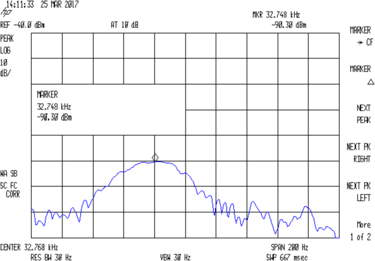
In order to probe a crystal’s response with decent resolution, I need a gadget to step a decent-quality sine wave by 0.01 Hz across the 10-to-100 kHz range and a logarithmic front end with a decent dynamic range. That’s prompted by looking at crystal responses through the SA’s 30 Hz resolution bandwidth:
Quartz Resonator 32.765 kHz – 34.6 pF
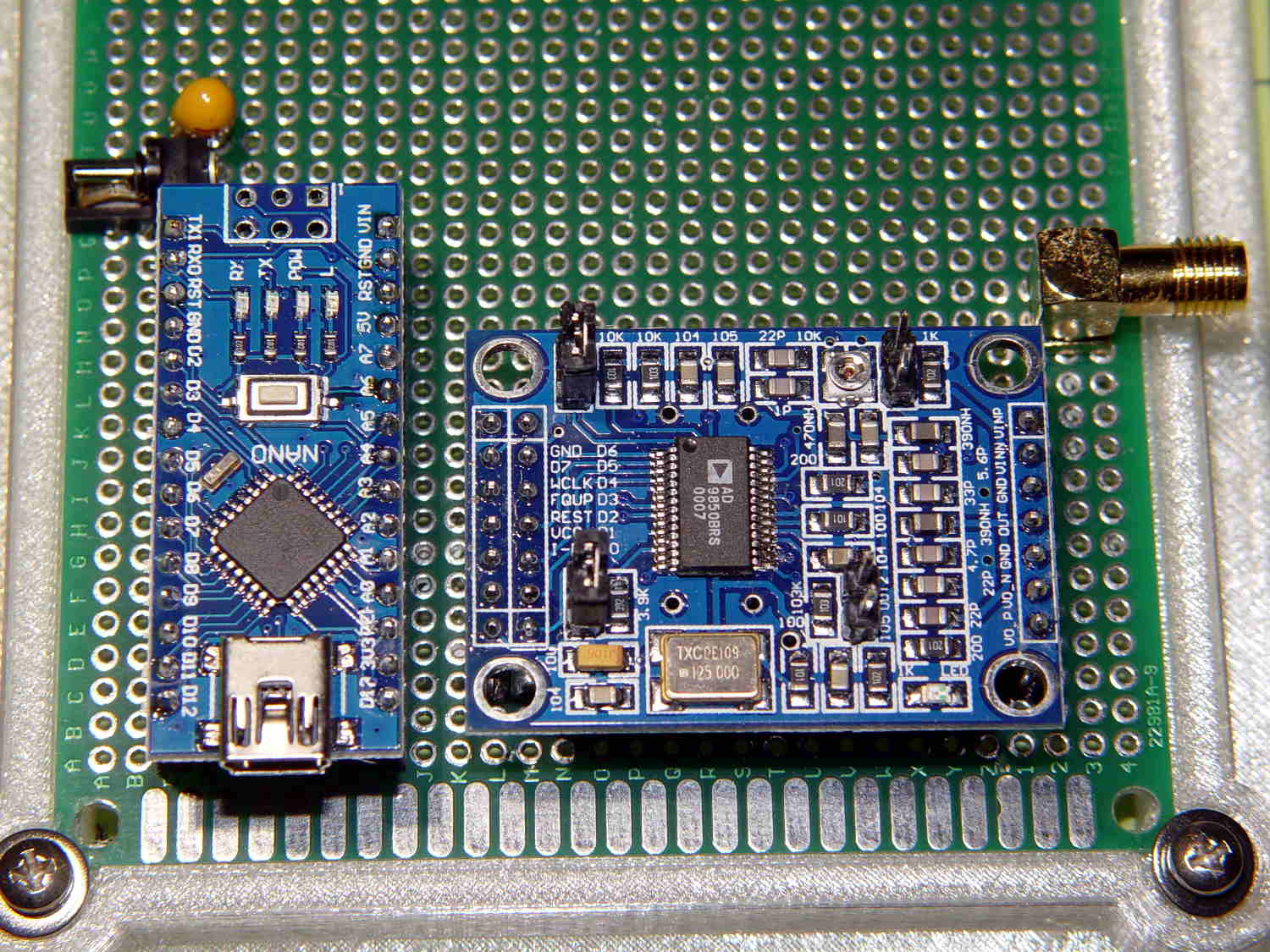
Mashing a cheap AD9850/AD9851 DDS board against an Arduino Pro Mini, adding a knob, and topping with a small display might be useful. A Raspberry Pi could dump the response data directly into a file via WiFi, which may be more complication that seems warranted.
The DDS boards come with absurdly high-speed clock generators of dubious stability; a slower clock might be better. A local 10 MHz oscillator, calibrated against the 10 MHz output of the HP 3801 GPS stabilized receiver would be useful. If the local oscillator is stable enough, a calibration adjustment might suffice: dial for 10 MHz out, then zero-beat with the GPS reference, so that the indicated frequency would be dead on to a fraction of 1 Hz.
The HP 8591 spectrum analyzer has a better-quality RF front end than I can possibly build (or imagine!), but, at these low frequencies, a simple RF peak detector and log amp based on the ADL5303 or ADL5306 should get close enough. One can get AD8302 / AD8310chips on boards from the usual low-budget suppliers; a fully connectorized AD8310 board may be a good starting point, as it’s not much more than the single-connector version.
With frequencies from 10 kHz to 100 kHz coming from a local oscillator, one might argue for a synchronous detector, formerly known as a lock-in amplifier. A Tayloe Detector might be a quick-and-dirty way to sweep a tracking-filter-and-detector over the frequency range. Because it’s a tracking generator, the filter bandwidth need not be very tight.
At some point, of course, you just digitize the incoming signal and apply DSP, but the whole point of this is to poke around in the analog domain. This must not turn into an elaborate software project, too.
The HP 8591 tracking generator doesn’t go below 100 kHz, so I used the FG085 DDS function generator as a source. I trust the 8591’s calibration more than the FG805’s, but right now I’m more interested in the differences between successive frequencies and the DDS can step in 1 Hz increments.
The output appears on the 8591, with a big hump comes from the analyzer’s 30 Hz IF filter response sweeping across what’s essentially a single-frequency input. The hump is not the crystal’s response spectrum!
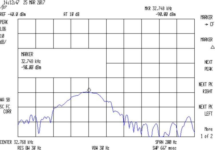
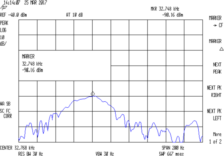
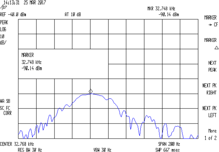
With the jumper installed to short the 33 pF cap, the output peaks at 32.764:
Quartz Resonator 32.763 kHz – no cap
Quartz Resonator 32.764 kHz – no cap
Quartz Resonator 32.765 kHz – no cap
Quartz Resonator 32.766 kHz – no cap
Removing the jumper to put the cap in the circuit, the response peaks at 32.765 kHz:
Quartz Resonator 32.763 kHz – 34.6 pF
Quartz Resonator 32.764 kHz – 34.6 pF
Quartz Resonator 32.765 kHz – 34.6 pF
Quartz Resonator 32.766 kHz – 34.6 pF
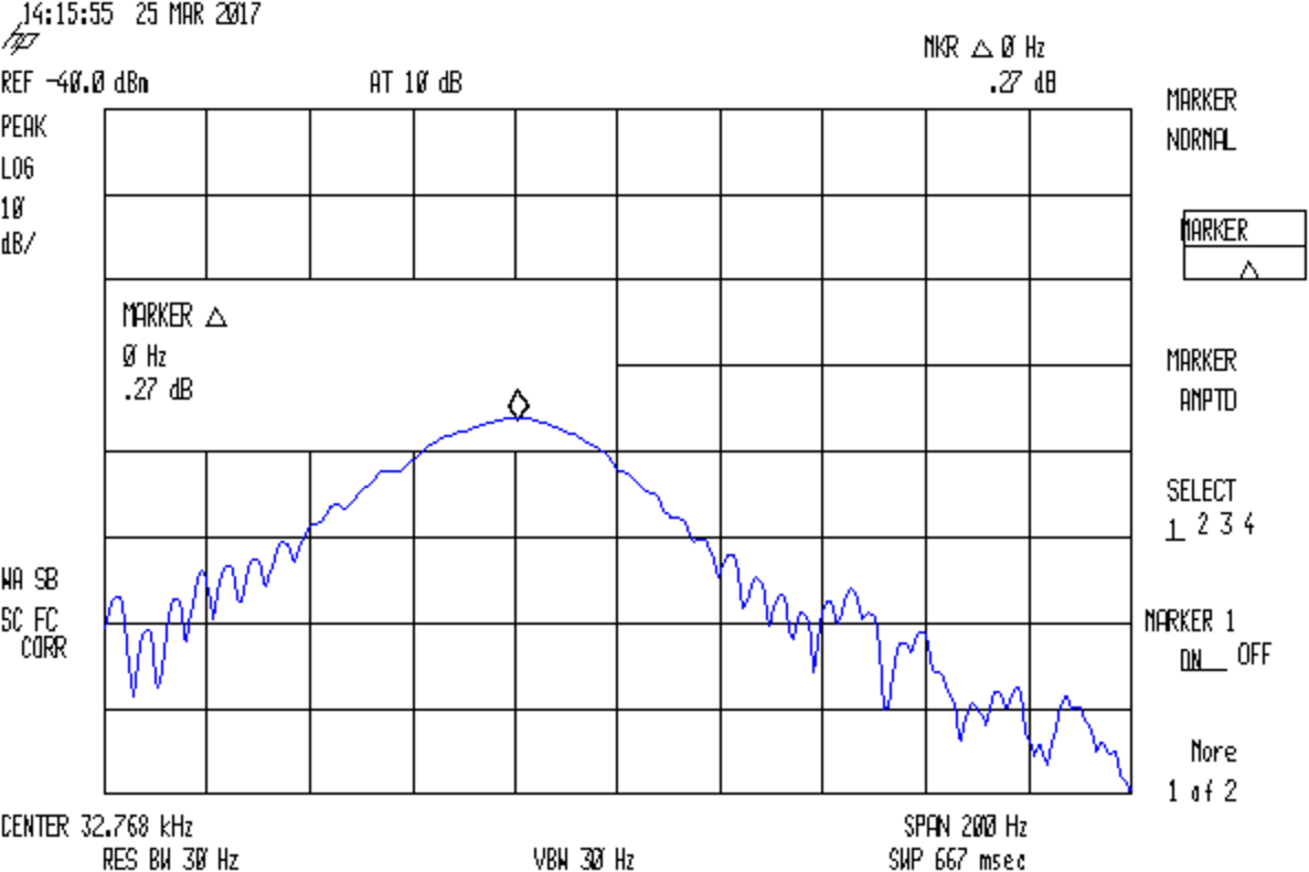
The marker delta shows the difference between the two peaks, ignoring their 1 Hz difference:
Quartz Resonator 32.764-5 no-34.6 pF delta
So I’d say the cap really does change the resonator series resonance by just about exactly 1 Hz.
With the jumper installed to remove the cap from the circuit, setting the reference marker at the 32.764 kHz peak, and measuring the relative response at 32.765 kHz :
Quartz Resonator 32.764-5 no cap delta
So the response peak is much much narrower than 1 Hz: being off-peak by 1 Hz knocks 13-ish dB from the response.
What’s painfully obvious: my instrumentation is totally inadequate for crystal measurements at these frequencies!