Ed Nisley's Blog: Shop notes, electronics, firmware, machinery, 3D printing, laser cuttery, and curiosities. Contents: 100% human thinking, 0% AI slop.
#from luma.core.interface.serial import spi
from luma.core.interface.serial import i2c

... snippage ...

# reduce SPI bus from default 8 MHz to (maybe) avoid OLED failure-to-start
#serial = spi(device=0,port=0,bus_speed_hz=1000000)

# use I2C bus to avoid SPI timing spec failure
serial = i2c(port=1,address=(0x78 >> 1))     # PCB label = 0x78, low bit = R/W
The OLED PCB lists the I2C address with the R/W bit
And then It Just Works, with one gotcha. Although the Python program shuts itself and the system down, the wall wart continues to supply power and, because the I2C bus doesn’t include a Reset line, the OLED display doesn’t know the RPi has gone away. So you must issue a command to turn it off before shutting down:
device.cleanup()        # ideally, switches to low-power mode
rc = subp.call(['sudo','shutdown','-P','now'])
Now, to discover what works … oddly … with these displays.
An Adafruit BNO055 connected to a Raspberry Pi 3 I2C bus, despite knowing it won’t work:
I2C 100kHz – BNO055 SCL 1 mA-div – B7 Rd error
The I2C bus ticks along at 100 kHz (nominal) = 62.5 kHz (actual), as described a while ago.
The three digital traces along the bottom are D0 = SCL, D1 = SDA, and D2 = trigger raised when the Python program detects an error.
The upper trace shows the SCL current (1 mA/div) between the Pi and the BNO055, as described yesterday, with the latter stretching the clock whenever the current goes negative.
The fourth burst is the BNO055 sending the chip’s temperature in response to a simple request:
I commend to your attention a useful tutorial on I2C bus protocols / transactions / signalling.
Over on the left, the BNO055 has SCL held low (-2 mA) during the ACK phase of the previous byte. The first upward SCL edge marks the ACK, with the BNO055 holding SDA low during the edge until the Pi drops SCL.
The BNO releases SDA when SCL goes low again, whereupon SDA goes high, exactly as it should.
Now, things gets ugly.
The -1 mA current on SCL shows both the Pi (+1 mA) and the BNO (-2 mA) are pulling SCL low. The BNO is clock-stretching after the ACK, which the Pi can’t handle.
The Pi seems to think the rising edge of SCL occurs when it stops pulling SCL down, at the point where the SCL current goes from -1 mA to -2 mA, halfway though the high SDA pulse. It reads SDA at that point and receives an incorrect binary 1 bit from SDA, because the BNO hasn’t yet seen a rising SCL edge.
The SCL rising edge occurs when the BNO055 releases SCL and produces the SCL sliver.
The two vertical cursors bracketing the sliver mark the 16 µs SCL timing produced by the Pi’s SCL clock, which is not the 10 µs you’d expect at 100 kHz.
The right cursor sits on the next rising edge, so the left cursor marks where SCL should rise: exactly where the Pi releases its hold on SCL and expects it to pop up.
That error happens about 6% of the time, producing a chip temperature 128 °C higher than reality. The other 94% of the reads either work correctly or, perhaps, encounter a bogus SDA state coincidentally delivering a binary zero that looks good.
Here’s a sample of a “good” read:
I2C 100kHz – BNO055 SCL 1 mA-div – B7 Rd OK – long SCL high
The stop bit is now off to the right, so the last rising SCL edge is the ACK. Counting leftward eight edges from the ACK, the left cursor marks where the SCL edge should be for bit B7. Instead it occurs instantly after the BNO releases its hold on SCL, shown by the transition from -2 mA to 0 mA. I don’t know the setup and hold times for the Pi’s I2C port, but 250-ish ns seem aggressive; I think the data transitions should happen close to the down-going SCL edges.
Running the I2C bus at 200 kHz seems to work fine, but it still has the same aggressive SDA-to-SCL setup time. Here’s a close look at the same situation as in the previous photo, with SCL set for 200 kHz:
This being a read, the BNO sets SDA to whatever it should be, then releases its clock-stretching hold on SCL about 200 ns later. The Pi raises SCL shortly thereafter and it apparently Just Works. Maybe it’s Good Enough to be consistent, but I’d like to run more tests before trusting it.
Anyhow, that’s how the Pi’s I2C hardware doesn’t handle a chip using clock stretching.
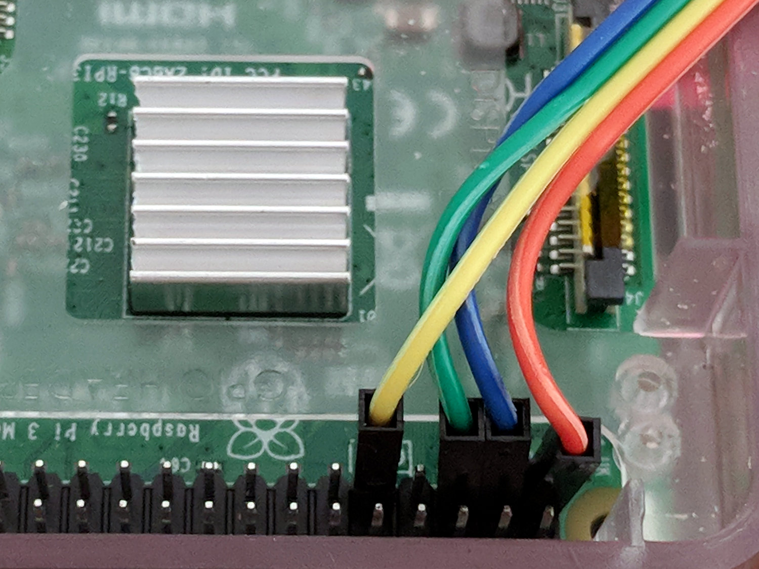
Clipping a Tek A6302 Hall effect current probe around the I2C SCL line between a Raspberry Pi and an Adafruit BNO055 sensor breakout board:
RPi I2C SCL current probe
The arrow on the probe points toward the Pi, so (conventional) current flowing through the 10 kΩ pulldown resistors into the Pi will be positive and current flowing from the Pi into the BNO055 will be negative.
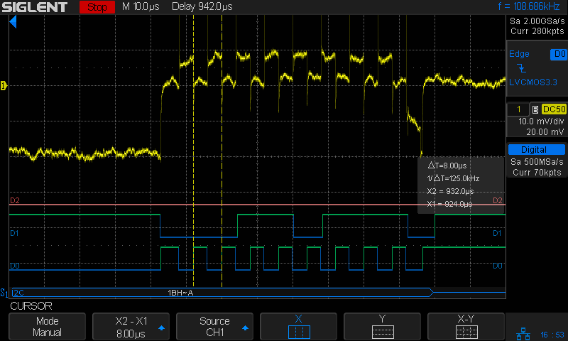
The top (yellow, analog) trace shows the current (1 mA/div) flowing through SCL:
I2C 100kHz – BNO055 SCL 1 mA-div – B7 Rd error
The four distinct current levels show the clock state:
+1 mA = Pi pulling low
0 mA = SCL high, no sinks active
-1 mA = Pi and BNO055 pulling low (clock stretching!)
-2 mA = BNO055 pulling low
The 0 mA baseline isn’t exactly at zero, because the AM502 amp has thermal drift like you wouldn’t believe, particularly with the gain cranked to 1 mA/div.
The probe + amp calibration seems slightly bogus: a 3.3 V supply pulled to ground at the Pi through the 10 kΩ resistor on the BNO055 breakout should deliver 0.33 mA, not nearly 1 mA. It’s close enough for now; I should cook up a probe calibration fixture.
The BNO055 sinks about 2 mA, which suggests a 1.6 kΩ pullup to 3.3 V on the Pi. Although you’re supposed to have one pullup on the I2C bus lines, some casual searching with the obvious keywords shows the Pi has 1.8 kΩ resistors on board.
Huh. Who knew?
So Adafruit’s advice to add 2.2 or 3.3 kΩ pullups at the BNO055 (admittedly, for a Beaglebone, not a Pi, but I suspect some folks miss such details) lowers the parallel resistance to about 1 kΩ, just about as low as you should go. It is not obvious to me that reducing the resistance by a factor of two will change the bus timing by enough to rescue a marginal situation (stipulated: the Pi is beyond marginal). TI has a useful App Note on the subject of I2C pull up resistance calculations.
Anyhow, I now have a way to examine the Pi’s clock stretching bugginess in grim detail, which is the point of this exercise. Note that the hardware bug has remained un-fixed (probably tagged WONTFIX) in all Pi silicon versions, including the Pi 3 as of 2018.
However, the actual SCL frequency comes from dividing the CPU’s core clock by an even integer, so you can’t always get what you want. The Pi 3 ticks along at 1.2 GHz (actually 1.1 GHz, because marketing) from a core clock of 550 MHz, so a 200 kHz clock calls for a 2750 divider: 550 MHz / 2750 = 200 kHz.
Actually measuring the SCL frequencies suggests something else is going on:
I2C 200kHz – actual 125kHz
D0, the bottom trace, is SCL, D1 is SDA, and D2 is a trigger output not used in this setup. The yellow analog trace is the current in the SCL line between the Pi and the BNO055, about which more later.
So a 200 kHz nominal frequency produces a 125 kHz actual frequency.
The BNO055 pulls the clock low (“clock stretching”), which can (and does) cause problems, but it’s not active during the main part of the transfer where the Pi determines the SCL frequency.
More measurement along those lines produces a table:
CPU Core Clock:
550
MHz
I2C SCL kHz
Nominal
Ratio
Actual
Ratio
250
2200
156.20
3521
200
2750
125.00
4400
150
3667
92.59
5940
125
4400
78.12
7040
100
5500
62.50
8800
50
11000
31.25
17600
25
22000
15.63
35189
10
55000
6.25
88000
Apparently, the code converting the nominal I2C rate in config.txt uses a table of divider values intended for another CPU core clock. AFAICT, the boot code could divide the actual core clock by the desired I2C frequency to produce the appropriate value.
I have no particular desire to Use The Source to figure out what’s going on …
[Update: Perhaps this comes along with CPU clock throttling due to temperature. For completeness, I should dump the temperature and actual clock speed.]
I’ve been coaching a high-school student (and his father!) on the intricacies of building a self-balancing robot; they’re doing all the hard work and I’m running interference with techie bugs. This one turned out to be particularly nasty.
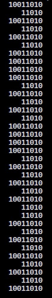
Reading the chip’s temperature sensor once every second produced this output:
BNO055 Sensor – Temperature Register vs I2C
He now knows why you must always leading-zero-fill binary values.
The shorter values say the chip ran at 26 °C, which means the longer values have a bogus binary 1 in bit 7. I2C bus transfers proceed MSB-first, so the Pi occasionally reads a bogus 1 at the first clock transition while reading the single temperature byte from the BNO055.
After some flailing around, we observed two types of I2C bus transactions.
Without clock stretching:
BNO055 – Normal I2C transaction
With clock stretching:
BNO055 – Clock-stretched I2C transaction
Contrary to what one might think from the lead-in description, the non-stretched version always produces the incorrect leading bit and the stretched version usually delivers the correct result.
He had previously installed the clock stretch workaround and we verified it was active. Turning it off had no effect, as did turning it back on again. The value uses units of the SCL period, so the modified value of 20000 produces 20×103 counts of 1/(100 k bit/s) = 2 s, far longer than any delay we observed. In fact, the default 640 μs would (apparently) suffice for the BNO055.
We noticed, but I did not record, nasty positive-going pulses on both SDA and SCL which were not due to noise or supply problems. As far as I can tell, the Pi does not maintain control over the I2C bus lines during some phases of the transaction, perhaps when the BNO055 invokes clock stretching, allowing the pullups to produce narrow upward glitches crossing the logic threshold. This will merit further study.
The solution, such as it is, seems to require slowing the I2C bus transactions to 25 kb/s, by inserting a line in the /boot/config.txt file:
dtparam=i2c_arm_baudrate=25000
... dummy line to reveal underscores ...
Slowing to 50 kb/s produced intermittent errors, while 25 kb/s seemed to completely eliminate them. This contradicts suggestions of proper operation at any speed other than the default 100 kb/s. Note: this applies to a single-byte data value and longer transactions remain to be tested.
I want to verify that the lower rate also eliminates the glitches, which will require running the Pi with the scope plumbed into its guts for some time. For obvious reasons, he’d rather get the robot working, so, until he encounters more problems, I won’t see the hardware …
Update: There’s now a way to do I²C with software bit-banging in a reasonably easy way. Thanks to Simon Blake for pointing this out!
Ex post facto notes from the third Squidwrench Electronics Workshop.
Exhibit various 50 Ω resistors, including my all-time favorite, a 600 W 3 GHz dummy load:
600 W Dummy Load Resistor
… down to a 1/8 Ω metal film resistor.
The dummy load’s N connector triggered a regrettable digression into RF, belatedly squelched because I wasn’t prepared to extemporize on AC concepts like reactance which we haven’t covered yet.
Discussion of resistor applications, power handling, power derating with temperature, etc:
Whiteboard – Session 3 – Resistor power derating
Why you generally won’t find 50 Ω load resistors in Raspberry Pi circuits. Cartridge heaters for 3D printers, not aluminum power resistors, although everyone agrees they look great:
Power resistors on heat spreader
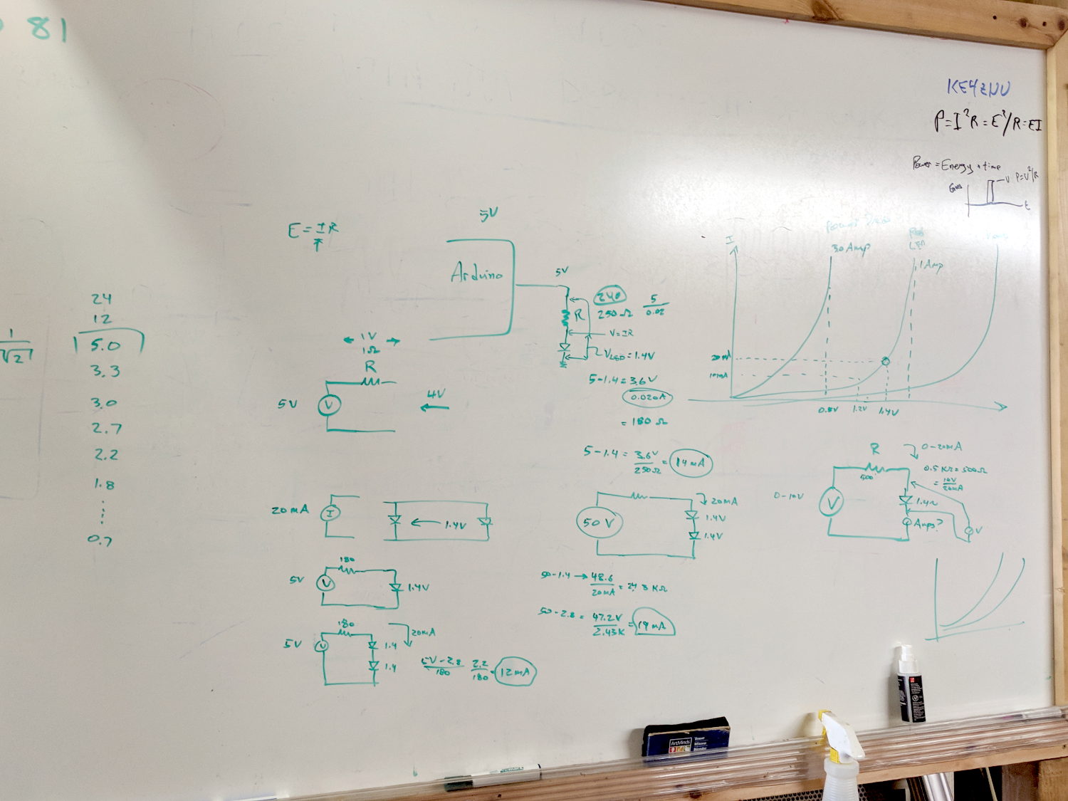
Discussion of voltage vs. current sources, why voltage sources want low internal resistances and current sources want high resistances. Bungled discussion of current sources by putting diodes in parallel; they should go in series to show how added voltage doesn’t change current (much!) in sources driven from higher voltages through higher resistances:
Whiteboard – Session 3 – Voltage vs Current Sources
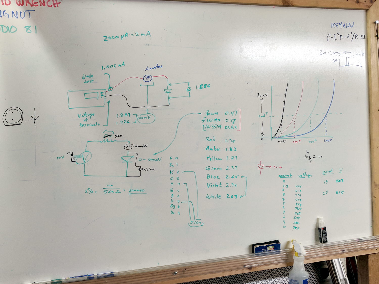
Use Siglent SDM3045X DMM in diode test mode to measure forward drop of power / signal / colored LEDs, discuss voltage variation with color / photon energy. Measure 1.000 mA test current for all forward voltages.
Compute series resistor (500 Ω) to convert adjustable power supply (the digital tattoo box, a lesson in itself) into reasonable current source; roughly 10 V → 20 mA. Find suitable resistor (560 Ω) in SqWr junk box parts assortment, digression into color band reading.
Wire circuit with meters to measure diode current (series!) and voltage (parallel!), measure same hulking power diode (after discovering insulating washers now in full effect) as before in 1 mA steps to 10 mA, then 15 and 20 mA, tabulate & plot results:
Whiteboard – Session 3 – Diode current vs forward drop
Discover warm resistor, compute power at 20 mA, introduce cautionary tales.
Lesson learned about never returning parts to inventory, with 560 Ω resistor appearing in diode drawer. Cautionary tales about having benchtop can of used parts as front-end cache for inventory backing store.
However, (nearly) all the remaining glitches seem to occur while writing a single row of pixels, which trashes the rest of the display and resolves on the next track update. That suggests slowing the timing during the initial hardware setup did change the results.
Another look at the Luma code showed I missed the Chip Enable (a.k.a. Chip Select in the SH1106 doc) change in serial.py:
def _write_bytes(self, data):
    gpio = self._gpio
    if self._CE:
        time.sleep(1.0e-3)
        gpio.output(self._CE, gpio.LOW)  # Active low
        time.sleep(1.0e-3)

    for byte in data:
        for _ in range(8):
            gpio.output(self._SDA, byte & 0x80)
            gpio.output(self._SCLK, gpio.HIGH)
            byte <<= 1
            gpio.output(self._SCLK, gpio.LOW)

    if self._CE:
        time.sleep(1.0e-3)
        gpio.output(self._CE, gpio.HIGH)
What remains unclear (to me, anyway) is how the code in Luma's bitbang class interacts with the hardware-based SPI code in Python’s underlying spidev library. I think what I just changed shouldn’t make any difference, because the code should be using the hardware driver, but the failure rate is now low enough I can’t be sure for another few weeks (and maybe not even then).
All this boils down to the Pi’s SPI hardware interface, which changes the CS output with setup / hold times measured in a few “core clock cycles”, which is way too fast for the SH1106. It seems there’s no control over CS timing, other than by changing the kernel’s bcm2708 driver code, which ain’t happening.
The Python library includes a no_cs option, with the caveat it will “disable use of the chip select (although the driver may still own the CS pin)”.
Running vcgencmd measure_clock core (usage and some commands) returns frequency(1)=250000000, which says a “core clock cycle” amounts to a whopping 4 ns.
Forcibly insisting on using Luma’s bitbang routine may be the only way to make this work, but I don’t yet know how to do that.
Obviously, I should code up a testcase to hammer the OLED and peer at the results on the oscilloscope: one careful observation outweighs a thousand opinions.