The Smell of Molten Projects in the Morning

Ed Nisley's Blog: Shop notes, electronics, firmware, machinery, 3D printing, laser cuttery, and curiosities. Contents: 100% human thinking, 0% AI slop.

Tag: RPi

Raspberry Pi

  • Squidwrench Electronics Workshop: Session 3

    Ex post facto notes from the third Squidwrench Electronics Workshop.

    Exhibit various 50 Ω resistors, including my all-time favorite, a 600 W 3 GHz dummy load:

    600 W Dummy Load Resistor
    600 W Dummy Load Resistor

    … down to a 1/8 Ω metal film resistor.

    The dummy load’s N connector triggered a regrettable digression into RF, belatedly squelched because I wasn’t prepared to extemporize on AC concepts like reactance which we haven’t covered yet.

    Discussion of resistor applications, power handling, power derating with temperature, etc:

    Whiteboard - Session 3 - Resistor power derating
    Whiteboard – Session 3 – Resistor power derating

    Why you generally won’t find 50 Ω load resistors in Raspberry Pi circuits. Cartridge heaters for 3D printers, not aluminum power resistors, although everyone agrees they look great:

    Power resistors on heat spreader
    Power resistors on heat spreader

    Discussion of voltage vs. current sources, why voltage sources want low internal resistances and current sources want high resistances. Bungled discussion of current sources by putting diodes in parallel; they should go in series to show how added voltage doesn’t change current (much!) in sources driven from higher voltages through higher resistances:

    Whiteboard - Session 3 - Voltage vs Current Sources
    Whiteboard – Session 3 – Voltage vs Current Sources

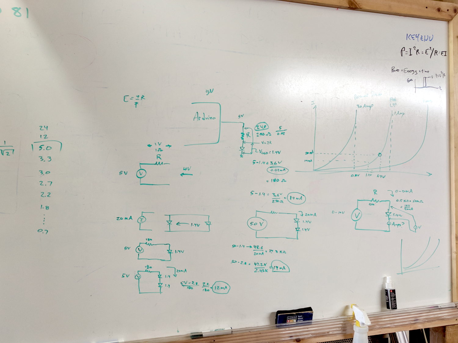
    Use Siglent SDM3045X DMM in diode test mode to measure forward drop of power / signal / colored LEDs, discuss voltage variation with color / photon energy. Measure 1.000 mA test current for all forward voltages.

    Compute series resistor (500 Ω) to convert adjustable power supply (the digital tattoo box, a lesson in itself) into reasonable current source; roughly 10 V → 20 mA. Find suitable resistor (560 Ω) in SqWr junk box parts assortment, digression into color band reading.

    Wire circuit with meters to measure diode current (series!) and voltage (parallel!), measure same hulking power diode (after discovering insulating washers now in full effect) as before in 1 mA steps to 10 mA, then 15 and 20 mA, tabulate & plot results:

    Whiteboard - Session 3 - Diode current vs forward drop
    Whiteboard – Session 3 – Diode current vs forward drop

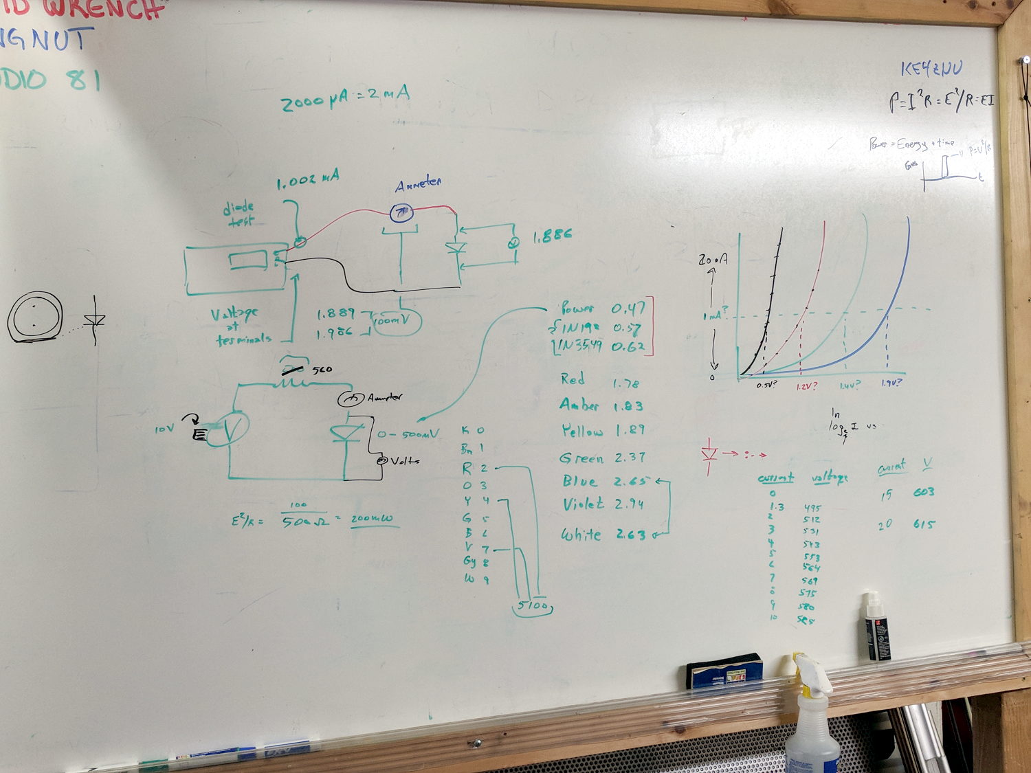
    Discover warm resistor, compute power at 20 mA, introduce cautionary tales.

    Lesson learned about never returning parts to inventory, with 560 Ω resistor appearing in diode drawer. Cautionary tales about having benchtop can of used parts as front-end cache for inventory backing store.

    Another intense day of bench work!

  • Streaming Radio Player: CE Timing Tweak

    Adding delays around the SPI control signal changes reduced the OLED glitch rate from maybe a few a week  to once a week, but didn’t completely solve the problem.

    However, (nearly) all the remaining glitches seem to occur while writing a single row of pixels, which trashes the rest of the display and resolves on the next track update. That suggests slowing the timing during the initial hardware setup did change the results.

    Another look at the Luma code showed I missed the Chip Enable (a.k.a. Chip Select in the SH1106 doc) change in serial.py:

    def _write_bytes(self, data):
        gpio = self._gpio
        if self._CE:
            time.sleep(1.0e-3)
            gpio.output(self._CE, gpio.LOW)  # Active low
            time.sleep(1.0e-3)
    
        for byte in data:
            for _ in range(8):
                gpio.output(self._SDA, byte & 0x80)
                gpio.output(self._SCLK, gpio.HIGH)
                byte <<= 1
                gpio.output(self._SCLK, gpio.LOW)
    
        if self._CE:
            time.sleep(1.0e-3)
            gpio.output(self._CE, gpio.HIGH)
    

    What remains unclear (to me, anyway) is how the code in Luma's bitbang class interacts with the hardware-based SPI code in Python’s underlying spidev library. I think what I just changed shouldn’t make any difference, because the code should be using the hardware driver, but the failure rate is now low enough I can’t be sure for another few weeks (and maybe not even then).

    All this boils down to the Pi’s SPI hardware interface, which changes the CS output with setup / hold times measured in a few “core clock cycles”, which is way too fast for the SH1106. It seems there’s no control over CS timing, other than by changing the kernel’s bcm2708 driver code, which ain’t happening.

    The Python library includes a no_cs option, with the caveat it will “disable use of the chip select (although the driver may still own the CS pin)”.

    Running vcgencmd measure_clock core (usage and some commands) returns frequency(1)=250000000, which says a “core clock cycle” amounts to a whopping 4 ns.

    Forcibly insisting on using Luma’s bitbang routine may be the only way to make this work, but I don’t yet know how to do that.

    Obviously, I should code up a testcase to hammer the OLED and peer at the results on the oscilloscope: one careful observation outweighs a thousand opinions.

  • Streaming Radio Player: Timing Tweaks

    Slowing the SPI clock and updating the drivers having had no noticeable effect on the OLED display corruption, I once again pondered the SH1106 controller timing specs.

    The chip reset seems remarkably slow, even at maximum VCC:

    SH1106 - Reset Timing Specs
    SH1106 – Reset Timing Specs

    I think the relevant code is in the luma.core driver’s serial.py file. On the RPi, it resides in /usr/local/lib/python2.7/dist-packages/luma/core/interface/.

    As far as I can tell, the bitbang class handles all the setup and teardown around the actual data transfers, but it’s not clear (to me, anyway) how it interacts with the underlying hardware SPI machinery.

    So, let’s add some sleepiness to the Reset code:

            if self._RST is not None:
                self._gpio.output(self._RST, self._gpio.LOW)  # Reset device
                time.sleep(1.0e-3)
                self._gpio.output(self._RST, self._gpio.HIGH)  # Keep RESET pulled high
                time.sleep(1.0e-3)
    

    A few milliseconds, rather than a few (hundred) microseconds, won’t make any perceptible difference.

    Similarly, the Chip Select and Address (Command/Data) signals require more delay than might occur between successive Python statements:

    SH1106 - SPI Address and Select Timing Specs
    SH1106 – SPI Address and Select Timing Specs

    This should do the trick, again with excessive delay:

            if self._DC:
                self._gpio.output(self._DC, self._cmd_mode)
                time.sleep(1.0e-3)
    
    ... snippage ...
    
            if self._DC:
                self._gpio.output(self._DC, self._data_mode)
                time.sleep(1.0e-3)
    
    ... snippage ...
    
            if self._CE:
                gpio.output(self._CE, gpio.LOW)  # Active low
                time.sleep(1.0e-3)
    
    ... snippage ...
    
            if self._CE:
                gpio.output(self._CE, gpio.HIGH)
                time.sleep(1.0e-3)
    

    Although it shouldn’t be necessary, I blew away the pyc files to prevent future confusion over who’s doing what with which.

    Once again, this will require several weeks to see whether the situation changes for the better.

  • MPCNC: Raspberry Pi Screw-down Case

    Directly from  0110-M-P’s Thingiverse thing, because a Raspberry Pi in a 75 mm VESA mount case will work for me:

    RPi in VESA case
    RPi in VESA case

    The hole fits a 25 mm fan, but the thing runs cool enough it should survive without forced air; think of it as a contingency. Mounting the case on standoffs seems like a Good Idea, however, as the bottom plate includes many vent slots for Good Circulation.

    The top plate builds upside-down, so I had Slic3r add teeny support plugs inside the recessed screw holes. I think button-head screws would fit neatly in the recesses, but we’re obviously not in this for the looks.

    The tiny white stud is a Reset switch hot-melt glued into the slot. I plan to just turn off the AC power after shutting the RPi down, so a power-on will suffice as a reset.

  • Streaming Radio Player: RPi and OLED Updates

    Because the OLED driver came from the pip package manager, not the Raspberry Pi’s system-level apt package manager, it (or they, there’s plenty of code under the hood) don’t get updated whenever I do system maintenance. The doc says this should do the trick:

    sudo -H pip install --upgrade luma.oled
    

    However, it turns out the new version has a slightly longer list of pre-requisite packages, causing the update to go toes-up at a missing package:

    Could not import setuptools which is required to install from a source distribution.
    Please install setuptools.
    

    So update (or install, for the new ones) the missing pieces:

    sudo apt-get install python-dev python-pip libfreetype6-dev libjpeg-dev build-essential
    

    Doing so produced a backwards-compatibility error in my Python code:

    ... change ...
    from luma.core.serial import spi
    ... into ...
    from luma.core.interface.serial import spi
    

    The motivation for all this fuffing and fawing came from watching some OLEDs wake up completely blank or become garbled in one way or another. Evidently, my slower-speed SPI tweak didn’t quite solve the problem, although it did reduce the frequency of failures. I have decided, as a matter of principle, to not embrace the garble.

    Soooo, let’s see how shaking all the dice affects the situation.

    It’s entirely possible the OLED controllers don’t quite meet their specs, of course, or have begun deteriorating for all the usual reasons.

  • Streaming Radio Player: Standard Galactic Alphabet

    Prompted by Jacob’s comment about the most recent OLED garble:

    RPi Streaming Player - Standard Galactic Alphabet
    RPi Streaming Player – Standard Galactic Alphabet

    If ya can’t fix it, feature it!

    That’s the First SGA Font from the Standard Galactic Font origin story. I copied the font file to one of the streamers, then re-aimed the font setup:

    #font1 = ImageFont.truetype('/usr/share/fonts/truetype/dejavu/DejaVuSansMono.ttf',14)
    font1 = ImageFont.truetype('/home/pi/sga.ttf',14)
    #font2 = ImageFont.truetype('/usr/share/fonts/truetype/dejavu/DejaVuSans.ttf',11)
    font2 = ImageFont.truetype('/home/pi/sga.ttf',11)
    

    It looks surprisingly good on such a low-res display.

    The user community seems divided over the update … [grin]

  • Streaming Radio Player: OLED Garble

    Even in the dim light of dawn, it’s obvious slowing the SPI clock to 1 MHz didn’t quite solve the problem:

    RPi OLED display - garbled
    RPi OLED display – garbled

    The display started up fine, became encrypted during the next few hours, and remained garbled as the track information changed. This is almost certainly a bad SPI transfer trashing the OLED module’s control registers.

    Dropping the clock to the absolute minimum of 0.5 MHz didn’t help, either:

    serial = spi(device=0,port=0,bus_speed_hz=500000)
    device = sh1106(serial)
    

    This particular display woke up blank after loading the new code, then worked OK after another reset. The other streamers lit up as expected on the first try, so the slower SPI isn’t making the situation instantly worse.

    Running the clock at 1 MHz definitely reduced the failure rate, which suggests it’s a glitchy thing.

    Good embedded systems practice suggests resetting the entire display from scratch every now and again, but my streamer code has no concept of elapsed time. Opening that particular can o’ worms would almost certainly result in an on-screen clock and I do not want to go there.

    I suppose I must get a new oscilloscope with SPI bus decoding to verify all the SPI setup and hold times …