The Smell of Molten Projects in the Morning

Ed Nisley's Blog: Shop notes, electronics, firmware, machinery, 3D printing, laser cuttery, and curiosities. Contents: 100% human thinking, 0% AI slop.

Tag: RPi

Raspberry Pi

  • Raspberry Pi Rotary Encoder: evdev Proof of Concept

    Raspberry Pi Rotary Encoder: evdev Proof of Concept

    After Bill Wittig pointed me in the right direction, writing a Python program to correctly read a rotary encoder knob on a Raspberry Pi is straightforward. At least given some hints revealed by knowing the proper keywords.

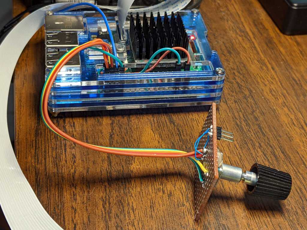
    First, enhance the knob’s survivability & usability by sticking it on a perfboard scrap:

    RPi rotary encoder - improved test fixture
    RPi rotary encoder – improved test fixture

    Then find the doc in /boot/overlays/README:

    Name: rotary-encoder
    Info: Overlay for GPIO connected rotary encoder.
    Load: dtoverlay=rotary-encoder,
    =
    Params: pin_a GPIO connected to rotary encoder channel A
    (default 4).
    pin_b GPIO connected to rotary encoder channel B
    (default 17).
    relative_axis register a relative axis rather than an
    absolute one. Relative axis will only
    generate +1/-1 events on the input device,
    hence no steps need to be passed.
    linux_axis the input subsystem axis to map to this
    rotary encoder. Defaults to 0 (ABS_X / REL_X)
    rollover Automatic rollover when the rotary value
    becomes greater than the specified steps or
    smaller than 0. For absolute axis only.
    steps-per-period Number of steps (stable states) per period.
    The values have the following meaning:
    1: Full-period mode (default)
    2: Half-period mode
    4: Quarter-period mode
    steps Number of steps in a full turnaround of the
    encoder. Only relevant for absolute axis.
    Defaults to 24 which is a typical value for
    such devices.
    wakeup Boolean, rotary encoder can wake up the
    system.
    encoding String, the method used to encode steps.
    Supported are "gray" (the default and more
    common) and "binary".

    Add a line to /boot/config.txt to configure the hardware:

    dtoverlay=rotary-encoder,pin_a=20,pin_b=21,relative_axis=1,steps-per-period=2

    The overlay enables the pullup resistors by default, so the encoder just pulls the pins to common. Swapping the pins reverses the sign of the increments, which may be easier than swapping the connector after you have it all wired up.

    The steps-per-period matches the encoder in hand, which has 30 detents per full turn; the default value of 1 step/period resulted in every other detent doing nothing. A relative axis produces increments of +1 and -1, rather than the accumulated value useful for an absolute encoder with hard physical stops.

    Reboot that sucker and an event device pops up:

    ll /dev/input
    total 0
    drwxr-xr-x 2 root root 80 Oct 18 07:46 by-path
    crw-rw---- 1 root input 13, 64 Oct 18 07:46 event0
    crw-rw---- 1 root input 13, 65 Oct 18 07:46 event1
    crw-rw---- 1 root input 13, 63 Oct 18 07:46 mice

    I’m unable to find the udev rule (or whatever) creating those aliases and, as with all udev trickery, the device’s numeric suffix is not deterministic. The only way you (well, I) can tell which device is the encoder and which is the power-off button is through their aliases:

    ll /dev/input/by-path/
    total 0
    lrwxrwxrwx 1 root root 9 Oct 18 07:46 platform-rotary@14-event -> ../event0
    lrwxrwxrwx 1 root root 9 Oct 18 07:46 platform-soc:shutdown_button-event -> ../event1

    The X axis of the mice device might report the same values, but calling a rotary encoder a mouse seems fraught with technical debt.

    The name uses the hex equivalent of the A channel pin number (20 = 0x14), so swapping the pins in the configuration will change the device name; rewiring the connector may be easier.

    Using the alias means you always get the correct device:

    # Rotary encoder using evdev
    # Add to /boot/config.txt
    #  dtoverlay=rotary-encoder,pin_a=20,pin_b=21,relative_axis=1,steps-per-period=2
    # Tweak pins and steps to match the encoder
    
    import evdev
    
    d = evdev.InputDevice('/dev/input/by-path/platform-rotary@14-event')
    print('Rotary encoder device: {}'.format(d.name))
    
    position = 0
    
    for e in d.read_loop():
        print('Event: {}'.format(e))
        if e.type == evdev.ecodes.EV_REL:
            position += e.value
            print('Position: {}'.format(position))
    

    Which should produce output along these lines:

    Rotary encoder device: rotary@14
    Event: event at 1603019654.750255, code 00, type 02, val 01
    Position: 1
    Event: event at 1603019654.750255, code 00, type 00, val 00
    Event: event at 1603019654.806492, code 00, type 02, val 01
    Position: 2
    Event: event at 1603019654.806492, code 00, type 00, val 00
    Event: event at 1603019654.949199, code 00, type 02, val 01
    Position: 3
    Event: event at 1603019654.949199, code 00, type 00, val 00
    Event: event at 1603019655.423506, code 00, type 02, val -1
    Position: 2
    Event: event at 1603019655.423506, code 00, type 00, val 00
    Event: event at 1603019655.493140, code 00, type 02, val -1
    Position: 1
    Event: event at 1603019655.493140, code 00, type 00, val 00
    Event: event at 1603019655.624685, code 00, type 02, val -1
    Position: 0
    Event: event at 1603019655.624685, code 00, type 00, val 00
    Event: event at 1603019657.652883, code 00, type 02, val -1
    Position: -1
    Event: event at 1603019657.652883, code 00, type 00, val 00
    Event: event at 1603019657.718956, code 00, type 02, val -1
    Position: -2
    Event: event at 1603019657.718956, code 00, type 00, val 00
    Event: event at 1603019657.880569, code 00, type 02, val -1
    Position: -3
    Event: event at 1603019657.880569, code 00, type 00, val 00
    

    The type 00 events are synchronization points, which might be more useful with more complex devices.

    Because the events happen outside the kernel scheduler’s notice, you (well, I) can now spin the knob as fast as possible and the machinery will generate one increment per transition, so the accumulated position changes smoothly.

    Much better!

  • Arducam Motorized Focus Camera: Focusing Equation

    Arducam Motorized Focus Camera: Focusing Equation

    The values written to the I²C register controlling the Arducam Motorized Focus Camera lens position are strongly nonlinear with distance, so a simple linear increment / decrement isn’t particularly useful. If one had an equation for the focus value given the distance, one could step linearly by distance.

    So, we begin.

    Set up a lens focus test range amid the benchtop clutter with found objects marking distances:

    Arducam Motorized Focus camera - test setup
    Arducam Motorized Focus camera – test setup

    Fire up the video loopback arrangement to see through the camera:

    Arducam Motorized Focus test - focus infinity
    Arducam Motorized Focus test – focus infinity

    The camera defaults to a focus at infinity (or, perhaps, a bit beyond), corresponding to 0 in its I²C DAC (or whatever). The blue-green scenery visible through the window over on the right is as crisp as it’ll get through a 5 MP camera, the HP spectrum analyzer is slightly defocused at 80 cm, and everything closer is fuzzy.

    Experimentally, the low byte of the I²C word written to the DAC doesn’t change the focus much at all, so what you see below comes from writing a focus value to the high byte and zero to the low byte.

    For example, to write 18 (decimal) to the camera:

    i2cset -y 0 0x0c 18 0

    That’s I²C bus 0 (through the RPi camera ribbon cable), camera lens controller address 0x0c (you could use 12 decimal), focus value 18 * 256 + 0 = 0x12 + 0x00 = 4608 decimal.

    Which yanks the focus inward to 30 cm, near the end of the ruler:

    Arducam Motorized Focus test - focus 30 cm
    Arducam Motorized Focus test – focus 30 cm

    The window is now blurry, the analyzer becomes better focused, and the screws at the far end of the yellow ruler look good. Obviously, the depth of field spans quite a range at that distance, but iterating a few values at each distance gives a good idea of the center point.

    A Bash one-liner steps the focus inward from infinity while you arrange those doodads on the ruler:

    for i in {0..31} ; do let h=i*2 ; echo "high: " $h ; let rc=1 ; until (( rc < 1 )) ; do i2cset -y 0 0x0c $h 0 ; let rc=$? ; echo "rc: " $rc ; done ; sleep 1 ; done

    Write 33 to set the focus at 10 cm:

    Arducam Motorized Focus test - focus 10 cm
    Arducam Motorized Focus test – focus 10 cm

    Then write 55 for 5 cm:

    Arducam Motorized Focus test - focus 5 cm
    Arducam Motorized Focus test – focus 5 cm

    The tick marks show the depth of field might be 10 mm.

    Although the camera doesn’t have a “thin lens” in the optical sense, for my simple purposes the ideal thin lens equation gives some idea of what’s happening. I think the DAC value moves the lens more-or-less linearly with respect to the sensor, so it should be more-or-less inversely related to the focus distance.

    Take a few data points, reciprocate & scale, plot on a doodle pad:

    Arducam Motorized Focus RPi Camera - focus equation doodles
    Arducam Motorized Focus RPi Camera – focus equation doodles

    Dang, I loves me some good straight-as-a-ruler plotting action!

    The hook at the upper right covers the last few millimeters of lens travel where the object distance is comparable to the sensor distance, so I’ll give the curve a pass.

    Feed the points into a calculator and curve-fit to get an equation you could publish:

    DAC MSB = 10.8 + 218 / (distance in cm)
    = 10.8 + 2180 / distance in mm)

    Given the rather casual test setup, the straight-line section definitely doesn’t support three significant figures for the slope and we could quibble about exactly where the focus origin sits with respect to the camera.

    So this seems close enough:

    DAC MSB = 11 + 2200 / (distance in mm)

    Anyhow, I can now tweak a “distance” value in a linear-ish manner (perhaps with a knob, but through evdev), run the equation, send the corresponding DAC value to the camera lens controller, and have the focus come out pretty close to where it should be.

    Now, to renew my acquaintance with evdev

  • Raspberry Pi Interrupts vs. Rotary Encoder

    Raspberry Pi Interrupts vs. Rotary Encoder

    Thinking about using a rotary encoder to focus a Raspberry Pi lens led to a testbed:

    RPi knob encoder test setup
    RPi knob encoder test setup

    There’s not much to it, because the RPi can enable pullup resistors on its digital inputs, whereupon the encoder switches its code bits to common. The third oscilloscope probe to the rear syncs on a trigger output from my knob driver.

    I started with the Encoder library from PyPi, but the setup code doesn’t enable the pullup resistors and the interrupt (well, it’s a callback) handler discards the previous encoder state before using it, so the thing can’t work. I kept the overall structure, gutted the code, and rebuilt it around a state table. The code appears at the bottom, but you won’t need it.

    Here’s the problem, all in one image:

    Knob Encoder - ABT - fast - overview
    Knob Encoder – ABT – fast – overview

    The top two traces are the A and B encoder bits. The bottom trace is the trigger output from the interrupt handler, which goes high at the start of the handler and low at the end, with a negative blip in the middle when it detects a “no motion” situation: the encoder output hasn’t changed from the last time it was invoked.

    Over on the left, where the knob is turning relatively slowly, the first two edges have an interrupt apiece. A detailed view shows them in action (the bottom half enlarge the non-shaded part of the top half):

    Knob Encoder - ABT - fast - first IRQs
    Knob Encoder – ABT – fast – first IRQs

    Notice that each interrupt occurs about 5 ms after the edge causing it!

    When the edges occur less than 5 ms apart, the driver can’t keep up. The next four edges produce only three interrupts:

    Knob Encoder - ABT - fast - 4 edges 3 IRQ
    Knob Encoder – ABT – fast – 4 edges 3 IRQ

    A closer look at the three interrupts shows all of them produced the “no motion” pulse, because they all sampled the same (incorrect) input bits:

    Knob Encoder - ABT - fast - 4 edges 3 IRQ - detail
    Knob Encoder – ABT – fast – 4 edges 3 IRQ – detail

    In fact, no matter how many edges occur, you only get three interrupts:

    Knob Encoder - ABT - fast - 9 edges 3 IRQ
    Knob Encoder – ABT – fast – 9 edges 3 IRQ

    The groups of interrupts never occur less than 5 ms apart, no matter how many edges they’ve missed. Casual searching suggests the Linux Completely Fair Scheduler has a minimum timeslice / thread runtime around 5 ms, so the encoder may be running at the fastest possible response for a non-real-time Raspberry Pi kernel, at least with a Python handler.

    If. I. Turn. The. Knob. Slowly. Then. It. Works. Fine. But. That. Is. Not. Practical. For. My. Purposes.

    Nor anybody else’s purposes, really, which leads me to think very few people have ever tried lashing a rotary encoder to a Raspberry Pi.

    So, OK, I’ll go with Nearer and Farther focusing buttons.

    The same casual searching suggested tweaking the Python thread’s priority / niceness could lock it to a different CPU core and, obviously, writing the knob handler in C / C++ / any other language would improve the situation, but IMO the result doesn’t justify the effort.

    It’s worth noting that writing “portable code” involves more than just getting it to run on a different system with different hardware. Rotary encoder handlers are trivial on an Arduino or, as in this case, even an ARM-based Teensy, but “the same logic” doesn’t deliver the same results on an RPi.

    My attempt at a Python encoder driver + simple test program as a GitHub Gist:

    # Rotary encoder test driver
    # Ed Nisley – KE4ZNU
    # Adapted from https://github.com/mivallion/Encoder
    # State table from https://github.com/PaulStoffregen/Encoder
    import RPi.GPIO as GPIO
    class Encoder(object):
    def __init__(self, A, B, T=None, Delay=None):
    GPIO.setmode(GPIO.BCM)
    self.T = T
    if T is not None:
    GPIO.setup(T, GPIO.OUT)
    GPIO.output(T,0)
    GPIO.setup(A, GPIO.IN, pull_up_down=GPIO.PUD_UP)
    GPIO.setup(B, GPIO.IN, pull_up_down=GPIO.PUD_UP)
    self.delay = Delay
    self.A = A
    self.B = B
    self.pos = 0
    self.state = (GPIO.input(B) << 1) | GPIO.input(A)
    self.edges = (0,1,-1,2,-1,0,-2,1,1,-2,0,-1,2,-1,1,0)
    if self.delay is not None:
    GPIO.add_event_detect(A, GPIO.BOTH, callback=self.__update,
    bouncetime=self.delay)
    GPIO.add_event_detect(B, GPIO.BOTH, callback=self.__update,
    bouncetime=self.delay)
    else:
    GPIO.add_event_detect(A, GPIO.BOTH, callback=self.__update)
    GPIO.add_event_detect(B, GPIO.BOTH, callback=self.__update)
    def __update(self, channel):
    if self.T is not None:
    GPIO.output(self.T,1) # flag entry
    state = (self.state & 0b0011) \
    | (GPIO.input(self.B) << 3) \
    | (GPIO.input(self.A) << 2)
    gflag = '' if self.edges[state] else ' – glitch'
    if (self.T is not None) and not self.edges[state]: # flag no-motion glitch
    GPIO.output(self.T,0)
    GPIO.output(self.T,1)
    self.pos += self.edges[state]
    self.state = state >> 2
    # print(' {} – state: {:04b} pos: {}{}'.format(channel,state,self.pos,gflag))
    if self.T is not None:
    GPIO.output(self.T,0) # flag exit
    def read(self):
    return self.pos
    def read_reset(self):
    rv = self.pos
    self.pos = 0
    return rv
    def write(self,pos):
    self.pos = pos
    if __name__ == "__main__":
    import encoder
    import time
    from gpiozero import Button
    btn = Button(26)
    enc = encoder.Encoder(20, 21,T=16)
    prev = enc.read()
    while not btn.is_held :
    now = enc.read()
    if now != prev:
    print('{:+4d}'.format(now))
    prev = now
    view raw encoder.py hosted with ❤ by GitHub
  • RPi HQ Camera: 4.8 mm Computar Video Lens

    RPi HQ Camera: 4.8 mm Computar Video Lens

    The Big Box o’ Optics disgorged an ancient new-in-box Computar 4.8 mm lens, originally intended for a TV camera, with a C mount perfectly suited for the Raspberry Pi HQ camera:

    RPi HQ Camera - Computar 4.8mm - front view
    RPi HQ Camera – Computar 4.8mm – front view

    Because it’s a video lens, it includes an aperture driver expecting a video signal from the camera through a standard connector:

    Computar 4.8 mm lens - camera plug
    Computar 4.8 mm lens – camera plug

    The datasheet tucked into the box (!) says it expects 8 to 16 V DC on the red wire (with black common) and video on white:

    Computar Auto Iris TV Lens Manual
    Computar Auto Iris TV Lens Manual

    Fortunately, applying 5 V to red and leaving white unconnected opens the aperture all the way. Presumably, the circuitry thinks it’s looking at a really dark scene and isn’t fussy about the missing sync pulses.

    Rather than attempt to find / harvest a matching camera connector, the cord now terminates in a JST plug, with the matching socket hot-melt glued to the Raspberry Pi case:

    RPi HQ Camera - 4.8 mm Computar lens - JST power
    RPi HQ Camera – 4.8 mm Computar lens – JST power

    The Pi has +5 V and ground on the rightmost end of its connector, so the Computar lens will be jammed fully open.

    I gave it something to look at:

    RPi HQ Camera - Computar 4.8mm - overview
    RPi HQ Camera – Computar 4.8mm – overview

    With the orange back plate about 150 mm from the RPi, the 4.8 mm lens delivers this scene:

    RPi HQ Camera - 4.8 mm Computar lens - 150mm near view
    RPi HQ Camera – 4.8 mm Computar lens – 150mm near view

    The focus is on the shutdown / startup button just to the right of the heatsink, so the depth of field is maybe 25 mm front-to-back.

    For comparison, the official 16 mm lens stopped down to f/8 has a tighter view with good depth of field:

    RPi HQ Camera - 16 mm lens - 150mm near view
    RPi HQ Camera – 16 mm lens – 150mm near view

    It’d be nice to have a variable aperture, but it’s probably not worth the effort.

  • Arducam Motorized Focus Camera Control

    Arducam Motorized Focus Camera Control

    Despite the company name name, the Arducam 5 MP Motorized Focus camera plugs into a Raspberry Pi’s camera connector and lives on a PCB the same size as ordinary RPi cameras:

    Arducam Motorized Focus RPi Camera - test overview
    Arducam Motorized Focus RPi Camera – test overview

    That’s a focus test setup to get some idea of how the control values match up against actual distances.

    It powers up focused at infinity (or maybe a bit beyond):

    Arducam Motorized Focus RPi Camera - default focus
    Arducam Motorized Focus RPi Camera – default focus

    In practice, it’s a usable, if a bit soft, at any distance beyond a couple of meters.

    The closest focus is around 40 mm, depending on where you set the ruler’s zero point:

    Arducam Motorized Focus RPi Camera - near focus
    Arducam Motorized Focus RPi Camera – near focus

    That’s the back side of the RPi V1 camera PCB most recently seen atop the mystery microscope objective illuminator.

    Pondering the sample code shows the camera focus setting involves writing two bytes to an I²C address through the video controller’s I²C bus. Enable that bus with a line in /boot/config.txt:

    dtparam=i2c_vc=on

    If you’re planning to capture 1280×720 or larger still images, reserve enough memory in the GPU:

    gpu_mem=512

    I don’t know how to determine the correct value.

    And, if user pi isn’t in group i2c, make it so, then reboot.

    The camera must be running before you can focus it, so run raspivid and watch the picture. I think you must do that in order to focus a (higher-res) still picture, perhaps starting a video preroll (not that kind) in a different thread while you fire off a (predetermined?) focus value, allow time for the lens to settle, then acquire a still picture with the video still running.

    The focus value is number between 0 and 1023, in two bytes divided, written in big-endian order to address 0x0c on bus 0:

    i2cset -y 0 0x0c 0x3f 0xff

    You can, of course, use decimal numbers:

    i2cset -y 0 0x0c 63 255

    I think hex values are easier to tweak by hand.

    Some tinkering gives this rough correlation:

    Focus value (hex)Focus distance (mm)
    3FFF45 (-ish)
    300055
    200095
    1000530
    0800850
    Arducam Motorized Focus Camera – numeric value vs mm

    Beyond a meter, the somewhat gritty camera resolution gets in the way of precise focusing, particularly in low indoor lighting.

    A successful write produces a return code of 0. Sometimes the write will inexplicably fail with an Error: Write failed message, a return code of 1, and no focus change, so it’s Good Practice to retry until it works.

    This obviously calls for a knob and a persistent value!

  • Raspberry Pi HQ Camera + 16 MM 10 MP Lens: Depth of Field

    Raspberry Pi HQ Camera + 16 MM 10 MP Lens: Depth of Field

    Part of the motivation for getting a Raspberry Pi HQ camera sensor was being able to use lenses with adjustable focus and aperture, like the Official 10 MP “telephoto” lens:

    RPi HQ Camera - aperture demo setup
    RPi HQ Camera – aperture demo setup

    Yes, it can focus absurdly close to the lens, particularly when you mess around with the back focus adjustment.

    With the aperture fully open at f/1.4:

    RPi HQ Camera - aperture demo - f 1.4
    RPi HQ Camera – aperture demo – f 1.4

    Stopped down to f/16:

    RPi HQ Camera - aperture demo - f 16
    RPi HQ Camera – aperture demo – f 16

    The field of view is about 60 mm (left-to-right) at 150 mm. Obviously, arranging the camera with its optical axis more-or-less perpendicular to the page will improve everything about the image.

    For normal subjects at normal ranges with normal lighting, the depth of field works pretty much the way you’d expect:

    At f/1.4, focused on the potted plants a dozen feet away:

    Raspberry Pi HQ Camera - outdoor near focus
    Raspberry Pi HQ Camera – outdoor near focus

    Also at f/1.4, focused on the background at infinity:

    Raspberry Pi HQ Camera - outdoor far focus
    Raspberry Pi HQ Camera – outdoor far focus

    In comparison, the laptop camera renders everything equally badly (at a lower resolution, so it’s not a fair comparison):

    Laptop camera - outdoors
    Laptop camera – outdoors

    Stipulated: these are screen captures of “movies” from raspivid over the network to VLC. The HQ sensor is capable of much better images.

    None of this is surprising, but it’s a relief from the usual phone sensor camera with fixed focus (at “infinity” if you’re lucky) and a wide-open aperture.

  • Mystery Microscope Objective Illuminator

    Mystery Microscope Objective Illuminator

    Rummaging through the Big Box o’ Optics in search of something else produced this doodad:

    Microscope objective illuminator - overview
    Microscope objective illuminator – overview

    It carries no brand name or identifier, suggesting it was shop-made for a very specific and completely unknown purpose. The 5× objective also came from the BBo’O, but wasn’t related in any way other than fitting the threads, so the original purpose probably didn’t include it.

    The little bulb fit into a cute and obviously heat-stressed socket:

    Microscope objective illuminator - bulb detail
    Microscope objective illuminator – bulb detail

    The filament was, of course, broken, so I dismantled the socket and conjured a quick-n-dirty white LED that appears blue under the warm-white bench lighting:

    Microscope objective illuminator - white LED
    Microscope objective illuminator – white LED

    The socket fits into the housing on the left, which screws onto a fitting I would have sworn was glued / frozen in place. Eventually, I found a slotted grub screw hidden under a glob of dirt:

    Microscope objective illuminator - lock screw
    Microscope objective illuminator – lock screw

    Releasing the screw let the fitting slide right out:

    Microscope objective illuminator - lamp reflector
    Microscope objective illuminator – lamp reflector

    The glass reflector sits at 45° to direct the light coaxially down into the objective (or whatever optics it was originally intended for), with the other end of the widget having a clear view straight through. I cleaned the usual collection of fuzz & dirt off the glass, then centered and aligned the reflection with the objective.

    Unfortunately, the objective lens lacks antireflection coatings:

    Microscope objective illuminator - stray light
    Microscope objective illuminator – stray light

    The LED tube is off to the right at 2 o’clock, with the bar across the reflector coming from stray light bouncing back from the far wall of the interior. The brilliant dot in the middle comes from light reflected off the various surfaces inside the objective.

    An unimpeachable source tells me microscope objectives are designed to form a real image 180 mm up inside the ‘scope tube with the lens at the design height above the object. I have the luxury of being able to ignore all that, so I perched a lensless Raspberry Pi V1 camera on a short brass tube and affixed it to a three-axis positioner:

    Microscope objective illuminator - RPi camera lashup
    Microscope objective illuminator – RPi camera lashup

    A closer look at the lashup reveals the utter crudity:

    Microscope objective illuminator - RPi camera lashup - detail
    Microscope objective illuminator – RPi camera lashup – detail

    It’s better than I expected:

    Microscope objective illuminator - RPi V1 camera image - unprocessed
    Microscope objective illuminator – RPi V1 camera image – unprocessed

    What you’re seeing is the real image formed by the objective lens directly on the RPi V1 camera’s sensor: in effect, the objective replaces the itsy-bitsy camera lens. It’s a screen capture from VLC using V4L2 loopback trickery.

    Those are 0.1 inch squares printed on the paper, so the view is about 150×110 mil. Positioning the camera further from the objective would reduce both the view (increase the magnification) and the amount of light, so this may be about as good as it get.

    The image started out with low contrast from all the stray light, but can be coerced into usability:

    Microscope objective illuminator - RPi V1 camera image - auto-level adjust
    Microscope objective illuminator – RPi V1 camera image – auto-level adjust

    The weird violet-to-greenish color shading apparently comes from the lens shading correction matrix baked into the RPi image capture pipeline and can, with some difficulty, be fixed if you have a mind to do so.

    All this is likely not worth the effort given the results of just perching a Pixel 3a atop the stereo zoom microscope:

    Pixel 3a on stereo zoom microscope
    Pixel 3a on stereo zoom microscope

    But I just had to try it out.