Ed Nisley's Blog: Shop notes, electronics, firmware, machinery, 3D printing, laser cuttery, and curiosities. Contents: 100% human thinking, 0% AI slop.
A few days ago I rode off to an eye doctor appointment and my ladies rode off later to meet me at the grocery store after they stopped in the garden to harvest root crops. This sort of thing is easy enough to synchronize with amateur radio, but this morning I didn’t hear a thing until they rolled up beside me in the store parking lot.
It seemed they could hear each other and me, but I couldn’t hear either of them. We’re all on 144.39 MHz, the APRS data frequency, with 100 Hz tone squelch to keep the robots out of our ears. Our daughter has the GPS APRS tracker feeding data into the mic input, which is why we’re using a data channel for tactical comm.
This has happened once or twice before, but it’s very intermittent. I now had sufficient motivation to disconnect the radio, an ancient ICOM IC-Z1A, from the bike and pith it on the Electronics Workbench for examination. The UT-93 Tone Squelch board is unplugged & flipped over, resting on the front half of the radio body at the lower-left of the photo.
Turns out that there’s nothing visibly wrong in there. I suspect it’s a molecule or two of oxidation on the (gold-plated!) connector between the UT-93 and the main board, because the UT-93’s held firmly in position by the black foam square you can see in the lower-left of the photo. The small white plug near the top of the UT-93 mates with the equally small socket on the main board, just to the left of the lithium secondary cell in the middle.
It’s all CMOS logic, of course, and there’s no actual load current involved. That’s the worst condition for contacts, as a dry connection simply doesn’t produce enough energy to burn through the least hint of oxidation. That’s why they use gold plating on connectors, but it’s been a long time since that board has moved at all; the foam square is deeply indented.
So I wiggled & jiggled all the ribbon-cable connectors while I was in there, buttoned everything back up, and the tone decoding works again. I hope this will continue…
Memo to Self: remove only the four black corner screws on the upper case, plus the two silver screws near the very bottom inside the battery compartment, and the two halves pop apart. No need to remove the mic and earphone plugs, whew!
For about the last week I’ve noticed a soft clicking-buzzing sound somewhere near the dashboard / center console of our 2000 Toyota Sienna. I tried some on-the-fly isolation, but it wasn’t related to motion, engine on/off, CD or tape player, fan, or anything else. Finally Mary noticed it, too, and we spent half an hour in the garage yanking fuses and wiggling things until we tracked it down to below the passenger seat.
Now, in the good old days, that was empty space, but in the Sienna it’s where the rear-area heater lives. Shoving the seat forward to the stop exposed the heater and, sure enough, it’s buzzing and clicking. Intermittently, somewhat randomly, but very steadily.
Rear Temperature Control
With that as a hint, I twisted the rear-area temperature control (on the headliner behind the driver seat) and shazam the noise stopped. The control has detents and when moving the control to each detent the heater makes a faint buzzing. I suspect the control adjusts a valve that regulates engine coolant flow inside the heater.
It’s not obvious whether the control is a pure-digital rotary encoder or a potentiometer, so I decided to investigate: it’s already sorta busted, what’s to lose? The bezel comes off by prying its door-side edge outward. The white plastic frame has two screws into the metal structure under the roof. The two electrical connectors are, of course, the positive-latching kind that you pull the little tab until you break your fingernail and then realize that you should push it instead.
Temperature Control – Interior View
Taking the control apart reveals that it’s a potentiometer with some switching contacts. The two bifurcated spring-finger contacts on the black plastic disk short the resistive element to the inner metallic track.
Resistive Element
The metal contacts appeared slightly grody, but with no major corrosion. The resistive track looked just fine.
The offending control position would be to the left side of the element as shown in the pictures here: there’s nothing obviously wrong at that spot. I think the maximum-heat position is off the resistive element entirely, resting on the far left end of the metal traces, but the control wasn’t quite set to that spot. Perhaps the problem was that the contacts became intermittent at the exact edge of the element.
I smoothed the collection of anti-oxidation grease over the tracks, covered the contacts with their own blobs, put everything back together, and it works fine.
We tend to put the control at A/C during the summer and at maximum heat during the winter. I suppose the poor thing got frustrated after we moved it a month or so ago…
The money saved with this repair might just pay to have the Toyota dealer replace the spark plugs. The shop manual says that task starts by removing the windshield bezel and all the stuff above the engine intake manifold; the job costs upwards of 300 bucks. I can barely see the rear plugs with a looong inspection mirror angled just so while lying on the floor under the van, so it’s truly a nontrivial operation.
I’m sure they have more different versions of these things than anyone can count, but when I unscrewed the kitchen sink aerator, this is what I found inside.
The yellow plastic filter actually has two parts, held together by a minuscule clickstop on the central post. You can pry the whole thing off the main body with your thumbnail or, as in the photo, just pop the top screen off.
Rinse the grit off the screen, snap it back together, screw everything back onto the spout. Done!
It’s amazing how much grit accumulates downstream of the whole-house water filter. On the other paw, having just replaced the water heater, I’m not that amazed.
Once again, the faucet O-ring seals are leaking. This happens about every two years, perhaps due to mineral buildup in the spout body despite the water softener. Fortunately, it’s a dribble rather than a spurt, so it’s not an emergency.
This is a Home Depot (or was it Lowe’s?) faucet, but they do not stock repair parts. Go to FaucetDirect.com, order these parts:
060366-0070A SPOUT SEAL KIT (on the main column)
060343-0070A SPACER WITH O-RINGS (below the valve cartridge)
030126-0070A BUTTON AND SCREW KIT (if you booger the button)
Popping off the button
Of course, order two or three of each, because FD has punitive shipping rates. Ten bucks for a few envelopes of O-rings? Sheesh… but the last time I tried to get ’em locally, they were No Stock. If I’ve got to wait around, I’ll have ’em delivered to my door.
[Update: that comment suggests you can now get ’em from Amazon.com]
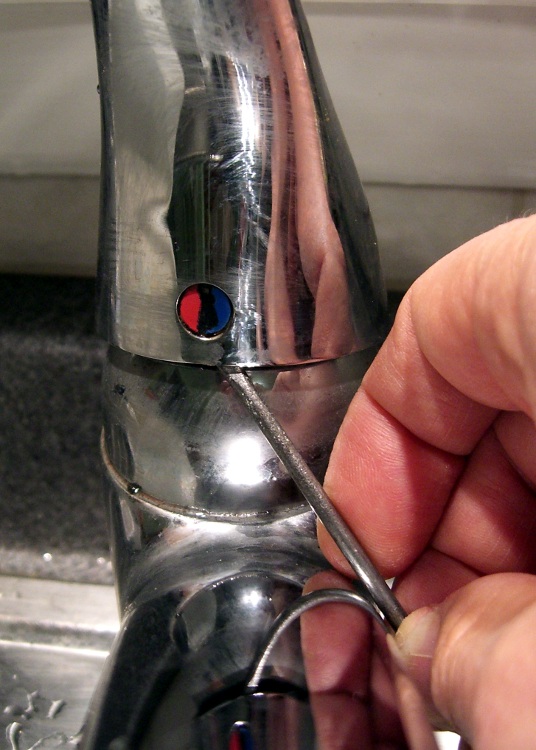
The first puzzle is how to get the faucet apart. After making a mess of it the first time, it turns out you poke a small flat screwdriver inside the handle and pop the red-blue button out. It’s held on by two small tabs, one on each side, and if you can just push one then it’ll ease right out. It is not a screw head, despite the recessed slot down the middle.
Poke a 3/32″ hex key in the hole, back out the setscrew a few more turns than you think it takes, pull the handle off.
The plastic cap retainer has two arms holding the escutcheon ring in place. Push inward, remove the escutcheon. The retainer is probably hopelessly jammed into the top of the faucet spout, so if it doesn’t come out, that’s OK.
Loosen the three screws holding down the valve cartridge, pull it straight up and out. You did turn the water off first, right? Remove the plastic spacer plate and three O-rings below it if you can; the plate may not fit through the retainer.
Faucet column
Now, get comfortable on the sink. Pull-and-twist the spout straight up with far more force than you think necessary. It will suddenly fly off and bloosh the water that’s been standing in the faucet column all over the place.
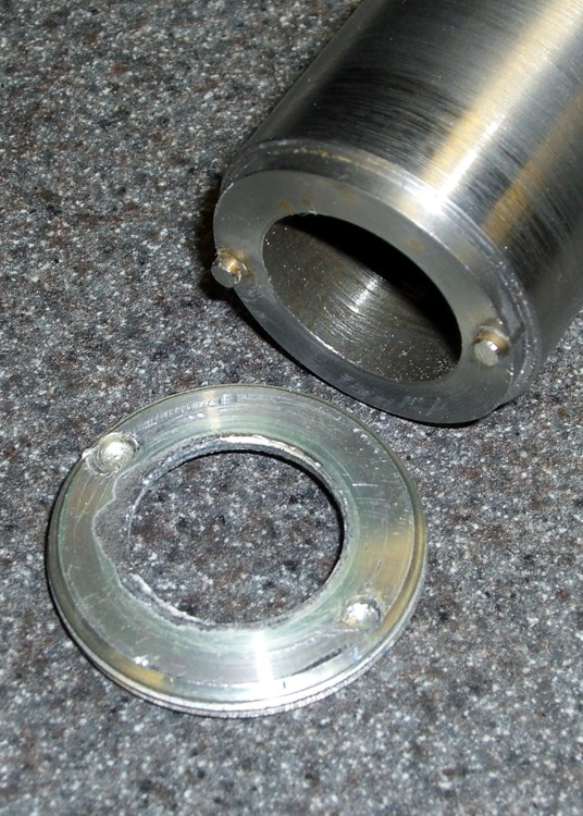
You’re left with a rather grody column and the two offending O-rings. Note the orientation of the silver flange ring at the bottom and the lower white plastic bearing ring. There may be three O-rings stuck to the top surface; they belong inside the spacer plate.
Remove all that hardware and scrub the grodosity off the column.
Hint: if you’re weak of stomach, never look inside your drinking water fixtures, because you’ll never drink tap water again.
I generally soak the spout in vinegar for a bit, scrub it out with a toothbrush, ease the remaining deposits off with a small screwdriver, then scrub the whole thing down with a ScotchBrite pad.
I apply a very very very thin layer of silicone lubricant to the bearing surfaces inside the column, which makes the next step possible.
Put the flange ring, the new O-rings, and plastic bearing rings in place, then slide the spout assembly straight down over the column until it bottoms out with a thump.
Install the new spacer plate & its O-rings, then reassemble all the other doodads in reverse order, turn on the water, and you’re done.
Then forget all the crud you saw in there that you couldn’t clean out.
For reasons that shouldn’t require the least bit of explanation by now, I had to dismantle(*) an old 2-D-cell Maglite. The operative word here is old, because you can find plenty of instructions & pix telling you how to dismantle the newer (post-2001, evidently), cheapnified Maglites. Mine dates back to the early days.
Unlike new(er) Maglites, the switch assembly in this one comes out through the front. An aluminum retaining nut holds it in place, as shown in the first picture. You’ll find directions telling you to unscrew the nut by jamming a pair of needle-nose pliers into the holes, but that’s not how it’s done.
The job calls for a pin wrench!
Measuring the dimensions is no BFD after you’ve got the damned thing apart, but I didn’t have that luxury. Given this was an American product from back in the Olde Days, I assumed everything was denominated in inches, which turned out to be close enough.
Pin Wrench Dimensions
The “Max” dimensions at the bottom are the actual ID measurements from the housing after disassembly, using telescoping gages. I made the wrench to the dimensions on the line just above and they worked fine.
Believe it or not, I found a steel cylinder in my scrap heap that was just exactly what I needed, right down to the 7/8″ bore in the middle. Not only that, it was free-machining steel. Whew!
The inner bore must clear the brass screw head sticking out of the lamp tower in the middle (which rides in a slot as part of the sliding focus mechanism). Once you’ve extricated the switch assembly, you remove that screw with a 2 mm (so much for hard inch dimensions) hex key. If you’re desperate, you can probably worry the screw out by goobering it with the aforementioned needle-nose pliers; it has an ordinary right-hand thread.
I turned the cylinder down in the lathe, then drilled the pin holes. That’s a mistake: the outside edge of the pins is exactly even with the OD of the wrench nose. If you do this, clean up the stock OD & face the ends to get a nice cylinder, drill the pin holes, then turn down the barrel clearance and nose. It need not be perfectly concentric, so stop worrying.
Pin Wrench Drill Clamping
I did the drilling using manual CNC on the Sherline mill, mostly because that’s the only way I could poke the holes in the right spots. The mill doesn’t have a lot of vertical headroom, so I clamped the wrench directly to the table and touched off the X and Y axes to put the origin in the center.
I got it all clamped down, removed the right-hand clamp to touch off on the +X side, then re-clamped it.
Drilling Pin Wrench
Center drill to fix the hole location. Drill 1/8″ about 0.250 deep: 3000 rpm, 10 ipm feed, use a little cutting lube. Do those both in sequence at each hole.
I sliced two overly long stubs from some 1/8″ drill rod with a Dremel cutoff wheel, dabbed JB Weld in the holes, and poked them in. The next morning I sliced them down to about the right length, cleaned up the ends with a file, broke the edges, and the wrench was good to go. The pin length in the drawing was what I’d have used if I could have measured the holes before taking it apart.
The pins were actually on the long side of 60 mils, just an itsy too much to keep the wrench flat on the nut. The next picture shows some gouging on one of the holes, due entirely to not engaging the wrench quite enough at first.
Pin Wrench and Maglite Retaining Nut
I thought about putting flats on the wrench, but simply grabbed it in the bench vise, swallowed it with the flashlight, engaged pins with holes, leaned into the wrench, and unscrewed the ring. It took a lot more force to get those threads turning than I expected, but the ring eventually spun out easily. Right-hand threads, of course; obvious after the fact.
Before you can remove the switch assembly, you must pry off the rubber switch cover, stick that 2 mm hex wrench down the hole thus revealed, and unscrew the setscrew ‘way down inside there. That backs the setscrew out of a recess in the housing that makes electrical contact with the negative end of the bottom D cell. Do that before you remove the ring, lest you forget.
Switch Housing and Lamp Tower Parts
Surprisingly, the blue plastic switch housing seems to be slightly soluble in potassium hydroxide. Who knew?
With the switch assembly out, you (well, I) can proceed to beat the corroded cells out by chucking the housing in the lathe (it exactly seats on the three-jaw chuck’s front face!) and ramming a fat dowel up its snout with a two-pound hammer.
Yeah, genuine Ray-O-Vac Maximum D cells: they all leak if you leave ’em in there long enough. This flashlight worked fine, right up to the point where I checked inside to see how long the cells had been in there. Oops.
I’m thinking of rebuilding it with some killer LED clusters up front; scrap the reflector, rework the switch assembly. Certainly that’d have better heatsinking than those absurd 3-watt LED bulb-like thingies.
(*) Yes, Maglite has a lifetime replacement warranty that even covers death due to battery corrosion. Now, I ask you, what’s the fun in that?
We got a boom box so Mom could have background music; the Olde Family Tube Radio was far beyond its Best Used By date.
Prompted by recent events around here, I checked it on a recent visit and, yup, more corrosion. In all fairness, the cells suggest “Best If Installed By Jan 99”, so they’re well past their date, too.
This used to be a whole lot less of a problem when flashlights and radios (without clocks!) were the only things using “dry cells”: when the battery went dead, the thing didn’t work and you replaced the cells.
Nowadays, we expect alkaline cells to supply keep-alive trickle current for memory backup; even after the cell corrodes, it still supplies that tiny current and we never notice what’s happening inside.
I’m beginning to loathe alkaline cells just like I loathe the small internal combustion engines in yard equipment.
The outdoor thermometer over my desk (which also displays UTC so I don’t have to reset the mumble clock twice a year) started blinking. That’s the usual sign of a dead battery and, yup, when I opened it up, that “leakproof” Eveready was pretty far gone.
Surprisingly, at least to me, the cell hovered around 1.1 V open-circuit and 800 mV under the meter’s “battery test” load. Given the amount of corrosion, I thought it would be flat dead.
The corrosion had crawled out of the compartment along the negative terminal and coated the entire metal tab with bluish-green crystals. Some protracted dabbing with vinegar, rinsing with wet cotton swabs, and drying put things pretty much back in order.
I usually scrawl the date on each cell when I install it, but either I didn’t do that here or the corrosion ate the ink. All I know is that it’s been up there for quite a few years; look at the discoloration where it faces the sun through the window!
The thing was a surplus freebie to begin with and has long since been fully depreciated…