I tote around an ancient Palm Zire 71, which suffices for my simple calendar & to-do lists. This is my second, as the first failed when the flexible cable connecting the guts to the charging / USB connector crapped out; turns out that the slide-to-open feature that reveals the crappy camera also stresses the flexy cable to the breaking point. Now I don’t do that any more.
The battery (well, it’s actually a single Li-Ion cell, but let’s not be pedantic) finally stopped taking a charge, so I did a full backup, tore the thing apart, and popped in a new battery. This being my second Zire 71, things went smoothly…
I got a stack of surplus Palm batteries some years ago, but they’re readily available from the usual suspects for prices ranging from $5 to $50. We’ll see how well mine survived their time in isolation.
The connectors don’t match, which means you just chop off them in mid-wire, then solder the old connector onto the new battery. A few dabs of Liquid Electrical Tape and it’s all good.
Some teardown instructions are there, with fairly small pix.
General reminders:
- Stick the teeny little screws on a strip of tape
- Watch out for the tiny plastic switch fin on the side
- Torx T06 screws on either side of the camera
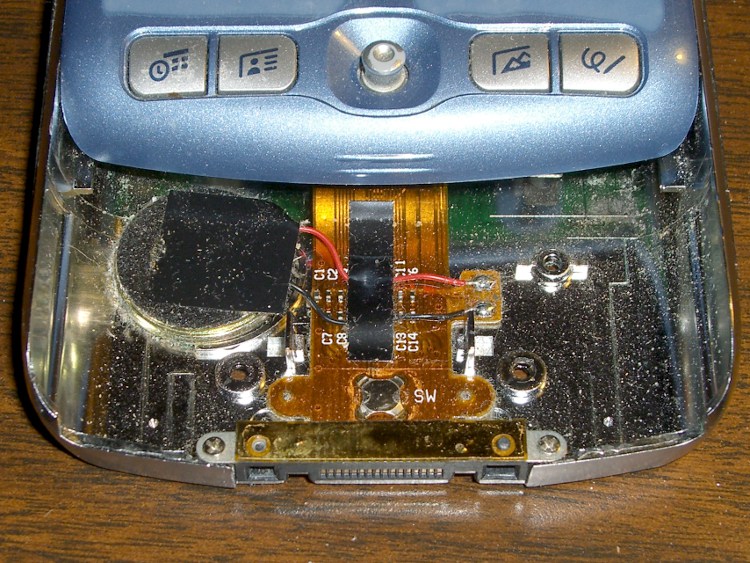
- The silver shield around the shutter button snaps under the sides with more force than you expect
- There’s a metal strip over the connector that can be taped back in place after the plastic posts snap off
- Gently pry the flexy cable up off the base, using the tabs on either side
- The speaker seems to be held in with snot
- The battery shield is not soldered in place!
- The battery adhesive comes off with a sloooowww pull
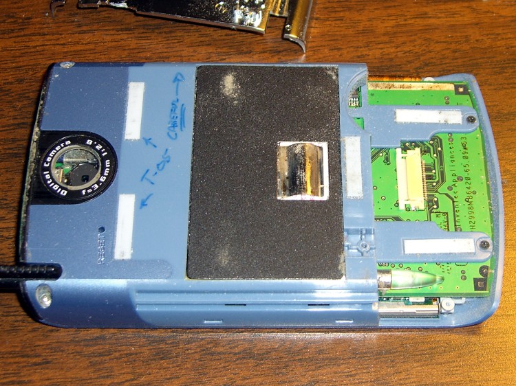
Although it may not be obvious, I replaced the crappy plastic window over the camera with a watch crystal. Much better picture quality, although much worse than my pocket camera.
Backup and restore with various pilot-link utilities:
pilot-xfer -p /dev/ttyUSB1  -b wherever
... hardware hackage ...
pilot-xfer -p /dev/ttyUSB1  -r wherever
pilot-dlpsh -p /dev/ttyUSB1 -c ntp
pilot-install-user -p /dev/ttyUSB1 -u "Ed Nisley"
The thing seems perfectly happy with a userid of 0, which is good because I haven’t the foggiest idea what else it could have been.


