Ed Nisley's Blog: Shop notes, electronics, firmware, machinery, 3D printing, laser cuttery, and curiosities. Contents: 100% human thinking, 0% AI slop.
For unknown reasons, probably having to do with the unmitigated disaster of trying to get an SDRPlay radio working with GNU Radio (about which, more later), Unicode keyboard input stopped working. This is not to be tolerated, because engineering notation requires a lot of Greek letters.
Unicode support seems to be baked into the lowest levels of the Linux operating system, although it’s not clear to me whether it’s in X, QT, GTK, or somewhere else. Googling the obvious keywords was unavailing; evidently this feature never ever fails or, more likely, very few people use it to any extent.
Note that I already have the Compose key set up, but Compose sequences don’t include Greek letters.
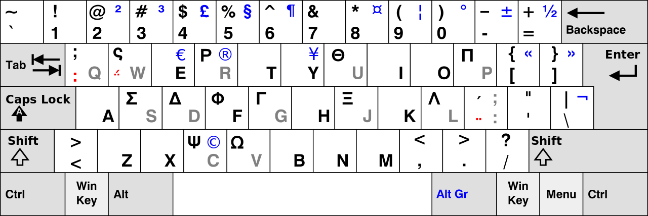
After considerable flailing, I added the Simple Greek keyboard layout and defined the (otherwised unused) Menu key as the keyboard layout switcher. That’s a pretty big hammer for a rather small problem; I devoutly hope Unicode mysteriously starts working again.
For reasons not relevant here, we (temporarily) have a set of pots with glass lids. One of lids had a remarkable amount of crud between the glass and the trim ring under the knob, which turned out to be corrosion falling off the screw. Trying to remove the screw produced the expected result:
CKC Pot Lid – broken screw in handle
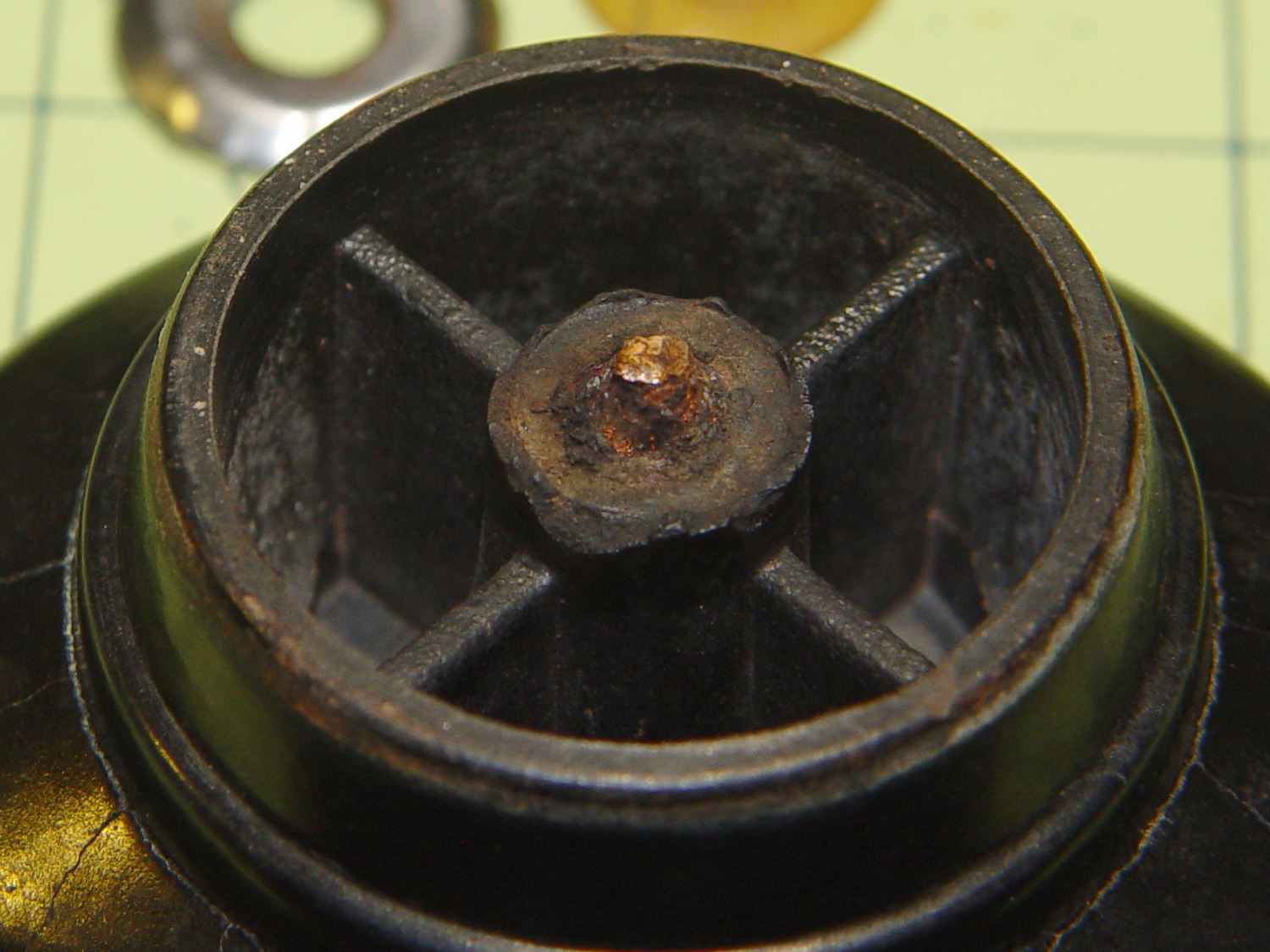
For whatever reason, they used an ordinary, not stainless, steel screw:
CKC Pot Lid – corroded screw
I figured I could mill the stub flat, drill out the remainder, install a new insert, and be done with it. The knob has a convex surface and, even though this looked stupid, I tried clamping it atop a wood pad:
CKC Pot Lid – precarious clamping
Two gentle cutter passes convinced me it was, in fact, a lethally stupid setup.
Soooo, I poured some ShapeLockpellets into a defunct (and very small) loaf pan, melted them in near-boiling water, and pressed the knob into the middle, atop some stretchy film to prevent gluing the knob in place:
CKC Pot Lid – ShapeLock bedding
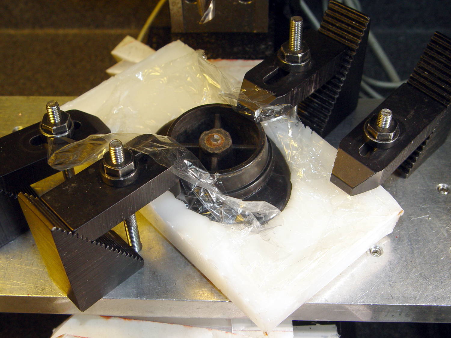
That’s eyeballometrically level, which is good enough, and the knob sits mechanically locked into the room-temperature plastic slab. Clamping everything down again makes for a much more secure operation:
CKC Pot Lid – clamped ShapeLock fixture
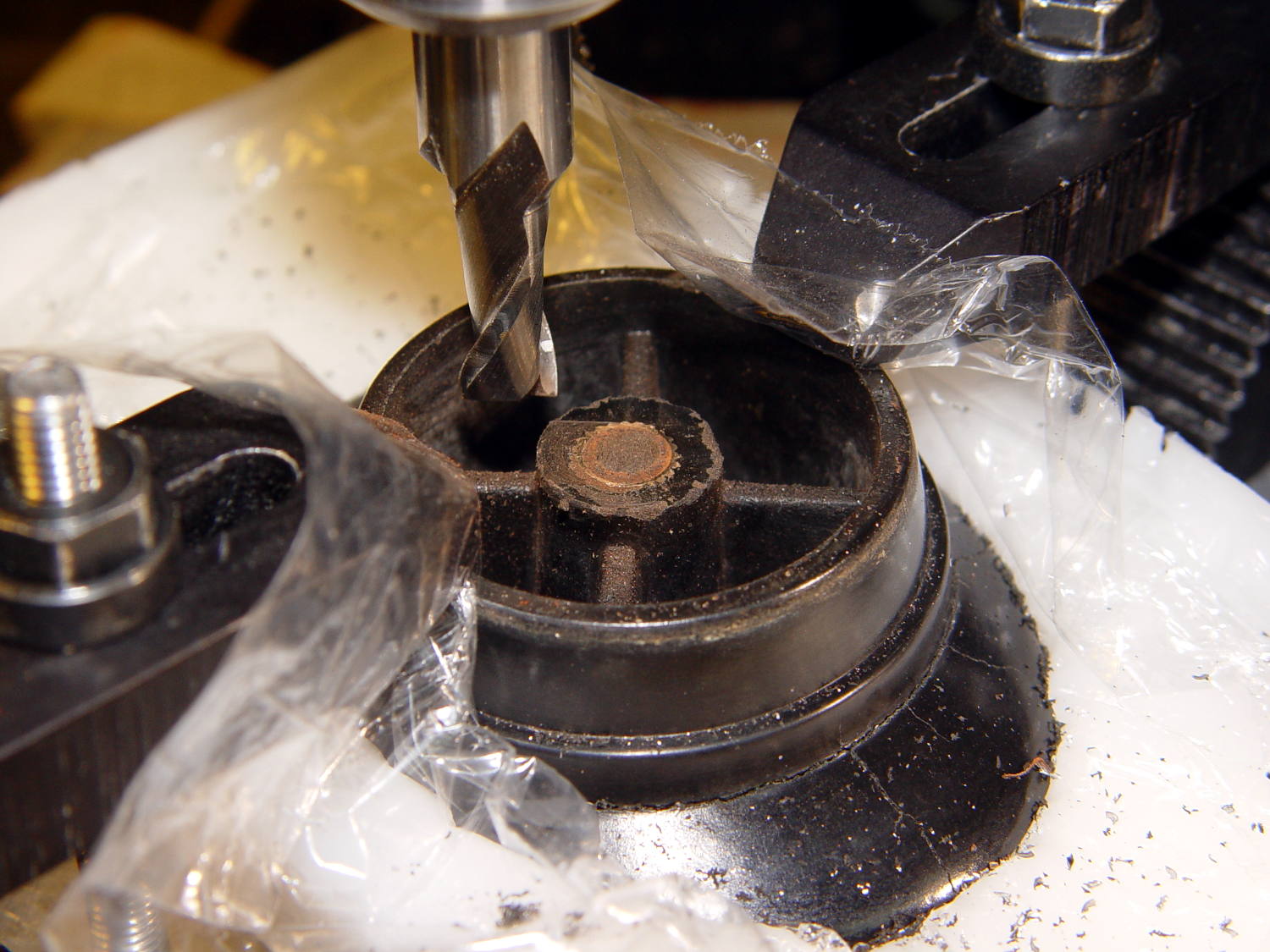
A few minutes of manual milling exposes the original brass insert molded into the knob, with the steel screw firmly corroded in the middle:
CKC Pot Lid – screw stub milled flat
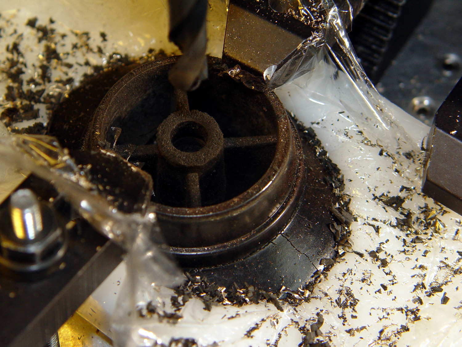
Center-drill, drill small-medium-large, and eventually the entire insert vanishes in a maelstrom of chips and dust:
CKC Pot Lid – OEM insert removed
Run a 10-32 stud into an insert, grab in drill chuck, dab JB Kwik around the knurls, press in place while everything’s still aligned in the Sherline, pause for curing, re-melt the ShapeLock, and the insert looks like it grew there:
CKC Pot Lid – new insert installed
Wonder to tell, a 1 inch 10-32 screw fit perfectly through the pot lid into the knob, with a dab of low-strength Loctite securing it. Reassemble everything in reverse order, and it’s all good:
CKC Pot Lid – repaired knob
Well, apart from those cracks. I decided I will not borrow trouble from the future: we’ll let those problems surface on their own and, if I’m still in the loop, I can fix them.
The pedal on Mary’s most recent Kenmore 158 lost its low-speed control, which meant I must add a few more graphite / carbon disks to the stacks:
Kenmore 158 – carbon disks
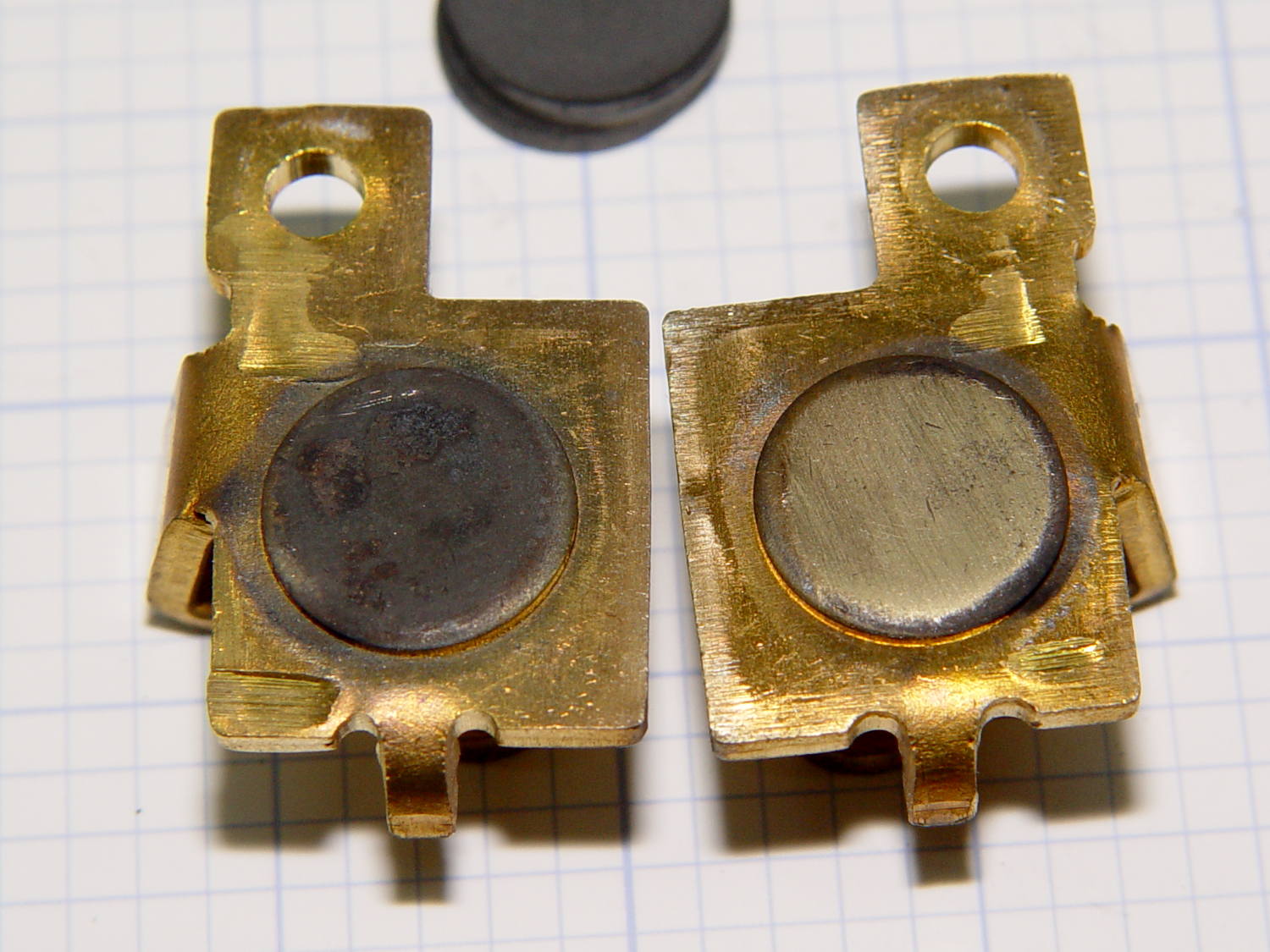
The contacts needed a bit of attention, too:
Kenmore 158 – carbon contact plates – detail
Contrary to what I found in the previousrheostats, these stacks end with a double-thick graphite disk backed up by a disk of brass shimstock, all of which needed cleaning, too. No broken disks, none severely eroded, no debris, just a general shortening of the stacks; I think the disks gradually turn into carbon dioxide.
Each stack has 42 graphite disks that average 0.79 mm thick, the double-thick disks measure 1.5 mm, and the brass shims are 0.30 mm = 12 mil. The punched contacts on those brass plates stand 0.95 mm proud of the surface.
With the big graphite plugs in place, the ceramic housing had 37 mm deep holes for the disk stacks. Subtracting the 0.95 mm contact leaves about 36 mm and, seeing as how the stacks add up to just under 36 mm overall, there’s barely room for one additional disk. I added one to each stack, buttoned the pedal up, and it works perfectly again.
I iterated this sequence three times before I caught on:
ssh into Raspberry Pi
Edit /etc/rc.local, save changes
Reboot, observe the changes had no effect
cat /etc/rc.local shows no changes
Then I:
Edited / saved
Listed the file to verify the changes
Rebooted, observe no effect from changes
Listed the file again: the changes were gone
Huh.
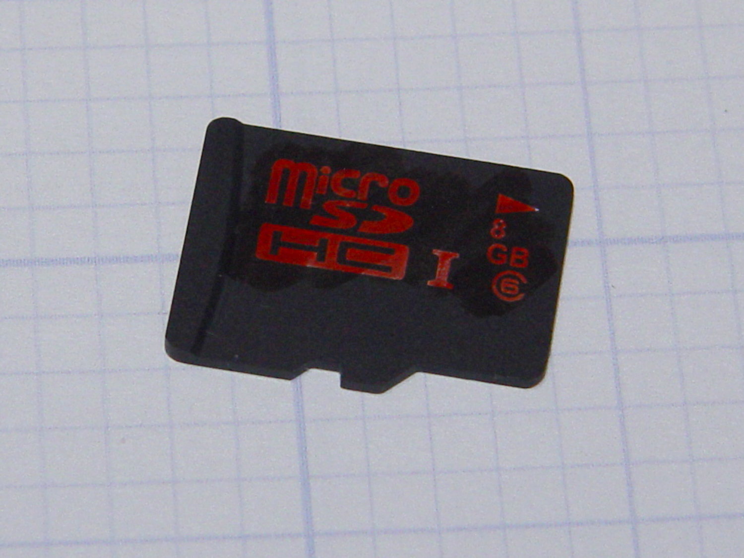
Defunct 8 GB MicroSDHC card
It turns out the card went read-only without warning, so I was displaying the contents of the file cache buffers after the edit, not the data stored on the card. Rebooting started with empty caches, read the previous file contents, and behaved accordingly.
The F3 utilities now live in the Ubuntu repository and no longer require compiling from source. The result:
sudo f3probe --time-ops /dev/sdb
F3 probe 6.0
Copyright (C) 2010 Digirati Internet LTDA.
This is free software; see the source for copying conditions.

WARNING: Probing normally takes from a few seconds to 15 minutes, but
         it can take longer. Please be patient.

Probe finished, recovering blocks... Done

Bad news: The device `/dev/sdb' is damaged

Device geometry:
	         *Usable* size: 0.00 Byte (0 blocks)
	        Announced size: 7.35 GB (15415296 blocks)
	                Module: 8.00 GB (2^33 Bytes)
	Approximate cache size: 0.00 Byte (0 blocks), need-reset=no
	   Physical block size: 512.00 Byte (2^9 Bytes)

Probe time: 164.4ms
 Operation: total time / count = avg time
      Read: 107.1ms / 4098 = 26us
     Write: 56.6ms / 2049 = 27us
     Reset: 0us / 0 = 0us
That card has been kicking around for a while and started out as a no-name generic in some random gadget. Of course, those fancy SonyMicroSDcards weren’t shining examples of durability, either.
I’m mildly astonished the streaming player worked perfectly with what amounts to a read-only filesystem, but that’s what caching is all about: there was no need to write the data to “disk”.
The power switch in my trusty Fordham FG-801 Function Generator failed with an accumulation of oxidation / crud on the contacts. That’s fix-able, but the switch contained not one, but two powerful springs, and puked its guts all over the floor around the Squidwrench Operating Table. Even with (a preponderance of) the parts in hand, I couldn’t figure out how to reassemble the thing; the only way out was to replace the switch.
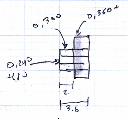
The OEM switch had a 0.360+ inch diameter pushbutton that fit into a ⅜ inch hole and, alas, my remaining stock of line-voltage switches had toggle levers and used ¼ inch holes. So I converted a bit of aluminum rod into a suitable bushing:
Fordham FG-801 Fn Gen – new switch hardware
The lock washer in the middle started with a much wider tab that I filed down into a tooth for the dent from a #2 center drill. Protip: center drills don’t walk off like twist drills, even when you hand-hold the front panel at the drill press with all the electronics dangling below.
The bushing dimension doodle:
Fordham FG-801 Function Generator – Replacement Switch Bushing
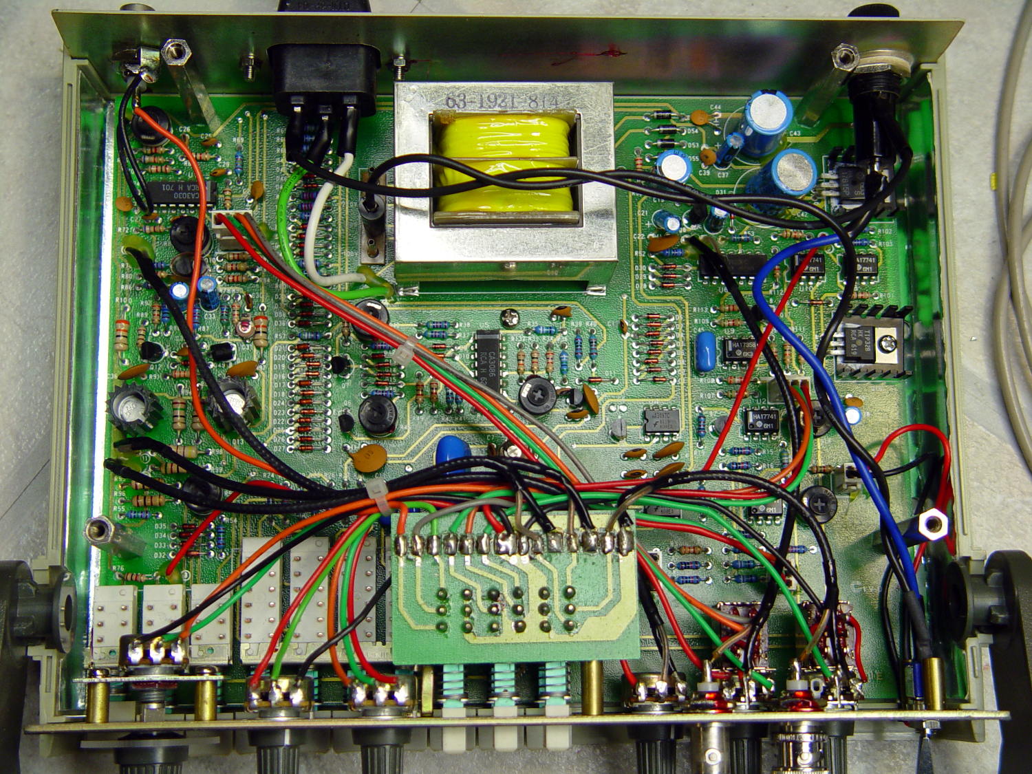
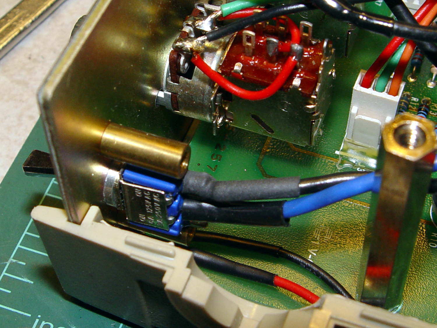
The internal wiring routes the 120 VAC line conductor to the switch, then to the fuse, then to the transformer. I don’t know whether it’s better to have an unfused switch or an unswitched fuse (surely there’s a UL spec for that), but I didn’t change anything. The new switch, being slightly smaller and mounting directly on the panel, required a new wire (the blue one) from the fuse:
Fordham FG-801 Fn Gen – power switch – installed
The OEM switch mounted on two round brass standoffs and, wonder to tell, the new switch fit between them!
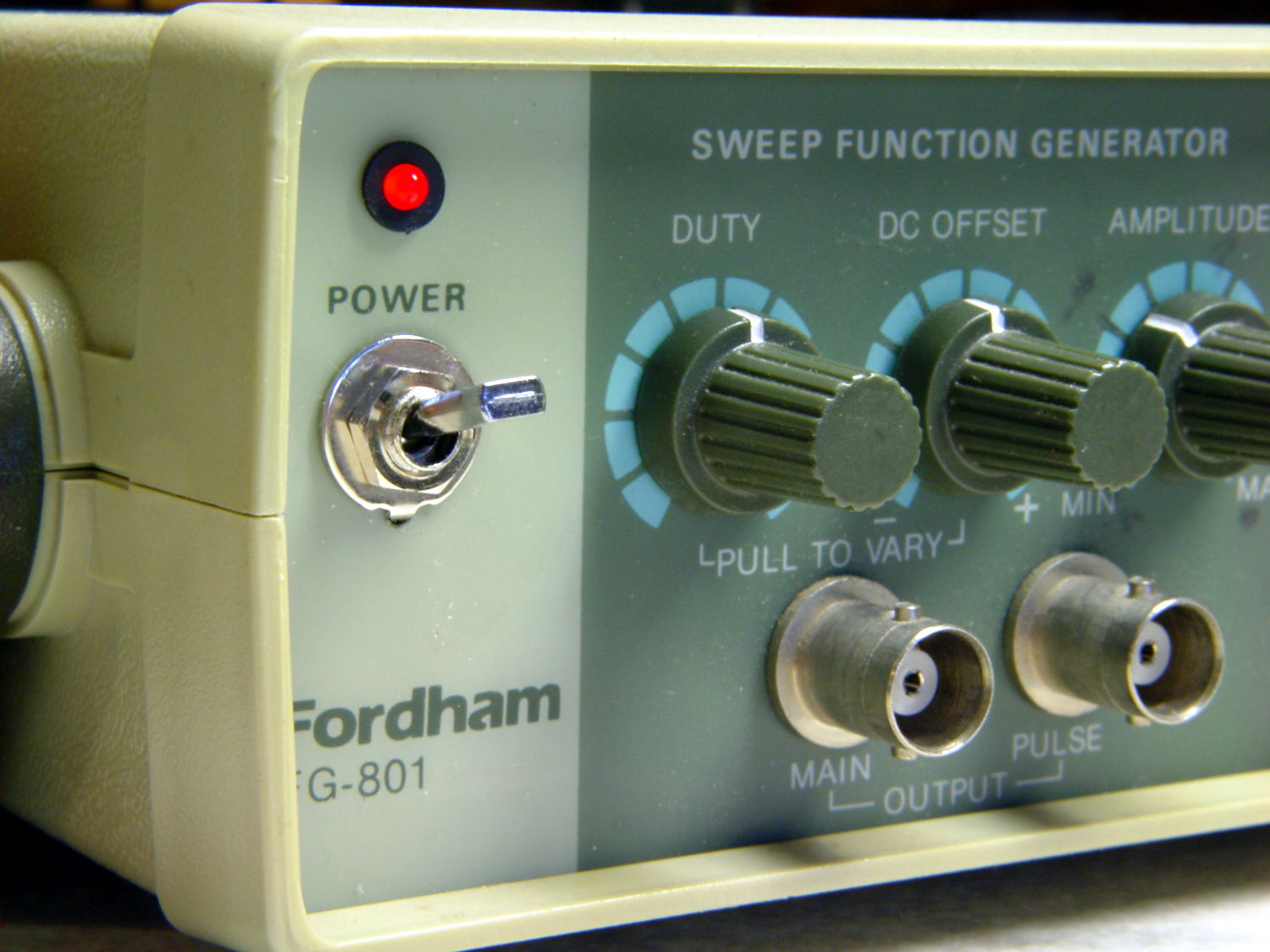
From the front, the new switch looks like it grew there:
Fordham FG-801 Fn Gen – switch in action
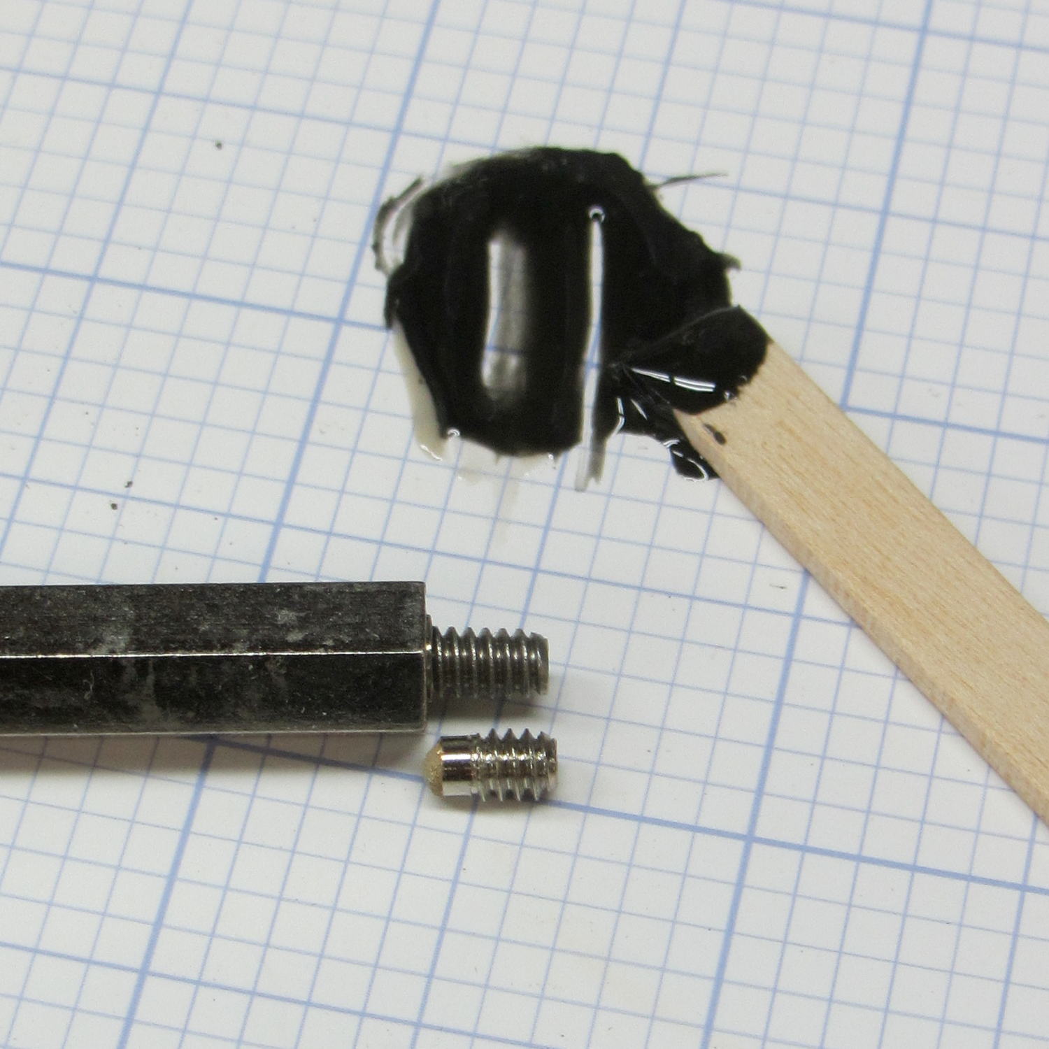
The PCB mounts to the top of the case with one screw and four hexagonal brass standoffs. The standoffs have 6-32 tapped holes on one end and a 6-32 stud on the other; one of those stud had broken off. A 6-32 stainless steel screw secured in a clearance hole with a dab of epoxy solved that problem:
Fordham FG-801 Fn Gen – standoff stud
I stood it vertically and tweaked the screw to be perpendicular while the epoxy cured.
Memo to Self: The next time around, put a nut on the stud to make sure the answer comes out right. I didn’t do this time to avoid epoxying the nut to the standoff.
The Hobo datalogger buried in the dirt under the patio kvetched about a low battery, which produced this surprising result:
Maxell CR2032 cell – early failure
Cells from the same lot have been doing just fine in the other dataloggers, so I hope this is a one-off weak cell and not the harbinger of another run of dead cells.