The Smell of Molten Projects in the Morning

Ed Nisley's Blog: Shop notes, electronics, firmware, machinery, 3D printing, laser cuttery, and curiosities. Contents: 100% human thinking, 0% AI slop.

Tag: MPCNC

Pimping and using a Mostly Printed CNC Machine

  • MPCNC: GCMC Configuration

    The default GCMC prolog(ue) spits out some G-Codes that GRBL doesn’t accept, requiring tweaks to the incantation.

    A first pass at a useful prolog, minus the offending codes:

    cat ~/.config/gcmc/prolog.gcmc 
    (prolog begins)
    G17 (XY plane)
    G21 (mm)
    G40 (no cutter comp)
    G49 (no tool length comp)
    G80 (no motion mode)
    G90 (abs distance)
    G94 (units per minute)
    (prolog ends)
    

    Including any of the usual “end of program” M-Codes in the epilog(ue) causes GRBL to pause before exiting the program, so leave only a placeholder:

    cat ~/.config/gcmc/epilog.gcmc 
    (epilog begins)
    (M2) (allow program to continue)
    (epilog ends)
    

    Having done a git clone into /opt/gcmc before building the program, the GCMC library routines live in:
    /opt/gcmc/library

    Limiting numeric values to two decimal places makes sense:
    -P 2

    With all that in hand, unleashing the compiler on an unsuspecting source file requires this jawbreaker:

    gcmc -P 2 -I /opt/gcmc/library \
    -G ~/.config/gcmc/prolog.gcmc \
    -g ~/.config/gcmc/epilog.gcmc \
    -o cycloids.ngc \
    cycloids.gcmc
    

    One might, of course, tuck all that into a little script, rather than depend on extracting it from the bash history as needed.

    The resulting G-Code file looks about right:

    head cycloids.ngc
    (prolog begins)
    G17 (XY plane)
    G21 (mm)
    G40 (no cutter comp)
    G49 (no tool length comp)
    G80 (no motion mode)
    G90 (abs distance)
    G94 (units per minute)
    (prolog ends)
    F2500.00
    [pi@MPCNC tmp]$ head -25 cycloids.ngc
    (prolog begins)
    G17 (XY plane)
    G21 (mm)
    G40 (no cutter comp)
    G49 (no tool length comp)
    G80 (no motion mode)
    G90 (abs distance)
    G94 (units per minute)
    (prolog ends)
    F2500.00
    G0 Z1.00
    (-- tracepath at Z=-1.00mm --)
    G0 X-145.50 Y-30.00
    G1 Z-1.00
    G1 X-145.51 Y-29.93
    
    ... vast snippage ...
    
    G1 X175.50 Y30.00
    G1 Z1.00
    G0 Z25.00
    (epilog begins)
    (M2)
    (epilog ends)
    

    Then it’s just a matter of tweaking cycloids.gcmc to make interesting things happen:

    GGMC Cycloids test patterns
    GGMC Cycloids test patterns
  • MPCNC: Tool Length Probe Station

    Having a tool length probe station on the Sherline, I had to build one for the MPCNC:

    MPCNC Tool Length Probe - plotter pen
    MPCNC Tool Length Probe – plotter pen

    It’s little more than a flange atop a wide base:

    MPCNC Tool Length Probe - Slic3r preview
    MPCNC Tool Length Probe – Slic3r preview

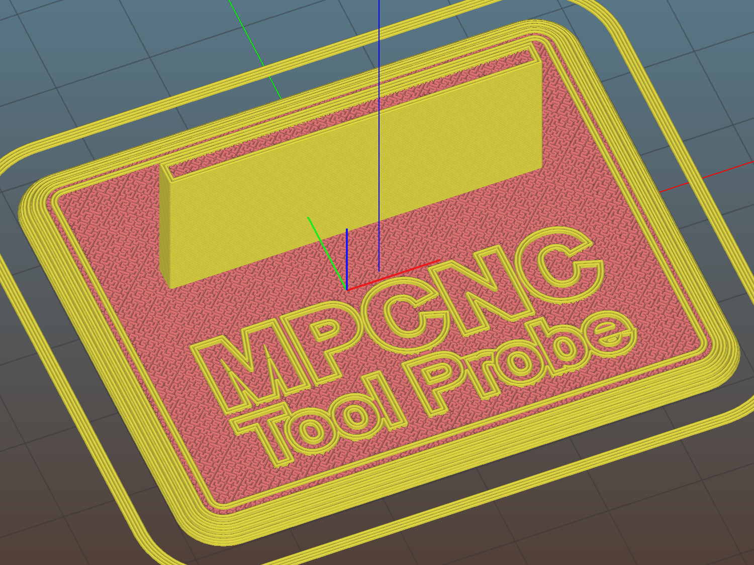
    The flange offset puts the switch actuator on the midline of the base, not that that matters, and the base features rounded corners and a suitable legend, because I can.

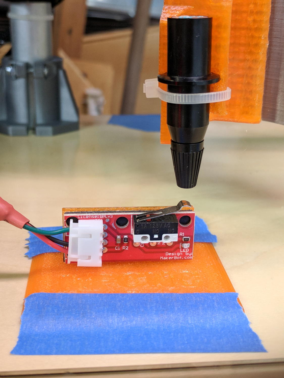
    I clipped the PCB’s through-hold leads nearly flush and stuck it to the flange with 3M permanent foam tape, which seems to work much better than screws & inserts for simple things that need never come apart.

    The Protoneer CNC Shield includes a Probe input on the GRBL-compliant A5, although it took me a while to find the legend on the SCL pin in the I2C header. I moved the endstop power jumper to another header, then conjured a quick-and-dirty connector:

    Protoneer CNC Shield - Tool Probe Wiring
    Protoneer CNC Shield – Tool Probe Wiring

    When I embed the endstop switch PCB in epoxy, I’ll add a drop to the connector while engaging in Magical Thinking. The whole Arduino + CNC Shield must go into an enclosure after I finish measuring the motor currents.

    To forestall discussions about switch repeatability and accuracy, suffice it to say the MPCNC doesn’t claim to be much more than a woodworking router, so those switches seem Good Enough.

    The OpenSCAD source code as a GitHub Gist:

    // MPCNC Tool Length Probe Station
    // Ed Nisley KE4ZNU – 2017-12-08
    /* [Extrusion] */
    ThreadThick = 0.25; // [0.20, 0.25]
    ThreadWidth = 0.40; // [0.40]
    function IntegerMultiple(Size,Unit) = Unit * ceil(Size / Unit);
    /* [Hidden] */
    Protrusion = 0.1; // [0.01, 0.1]
    HoleWindage = 0.2;
    /* [Sizes] */
    EndstopPCB = [40.0,16.5,1.6]; // endstop PCB
    ComponentHeight = 6.0; // max component height above PCB
    SwitchOffset = [35.0,21.0,4.75]; // touch point center from lower left PCB corner
    SwitchTravel = 2.5; // first touch to switch actuation
    TapeThick = 1.0; // foam mounting tape
    WallThick = 4.0; // basic wall & floor thickness
    BaseRadius = 5.0;
    Base = [IntegerMultiple(EndstopPCB[0] + 2*BaseRadius,20),
    IntegerMultiple(EndstopPCB[2] + TapeThick + WallThick + 2*BaseRadius,2*25),
    2.0];
    NumSides = 8*4;
    TextDepth = 2*ThreadThick;
    //- Build it
    union() {
    difference() {
    hull()
    for (i=[-1,1], j=[-1,1])
    translate([i*(Base[0]/2 – BaseRadius),j*(Base[1]/2 – BaseRadius),0])
    resize([0,0,Base[2]])
    intersection() {
    cylinder(r=BaseRadius,h=BaseRadius,$fn=NumSides);
    sphere(r=BaseRadius,$fn=NumSides);
    }
    translate([0,0,Base[2] – TextDepth])
    linear_extrude(height=TextDepth + Protrusion) {
    translate([0,-10,0])
    text(text="MPCNC",size=8,spacing=1.05,font="Arial:style=Bold",halign="center");
    translate([0,-18,0])
    text(text="Tool Probe",size=6,spacing=1.05,font="Arial:style=Regular",halign="center");
    }
    }
    translate([0,
    WallThick/2 + TapeThick + SwitchOffset[2],
    (EndstopPCB[1] – Protrusion)/2 + Base[2]])
    cube([EndstopPCB[0],WallThick,EndstopPCB[1] + Protrusion],center=true);
    }

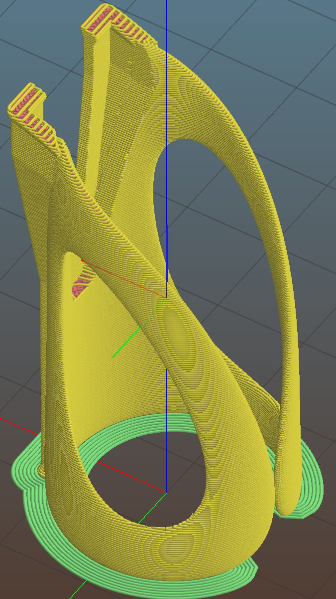
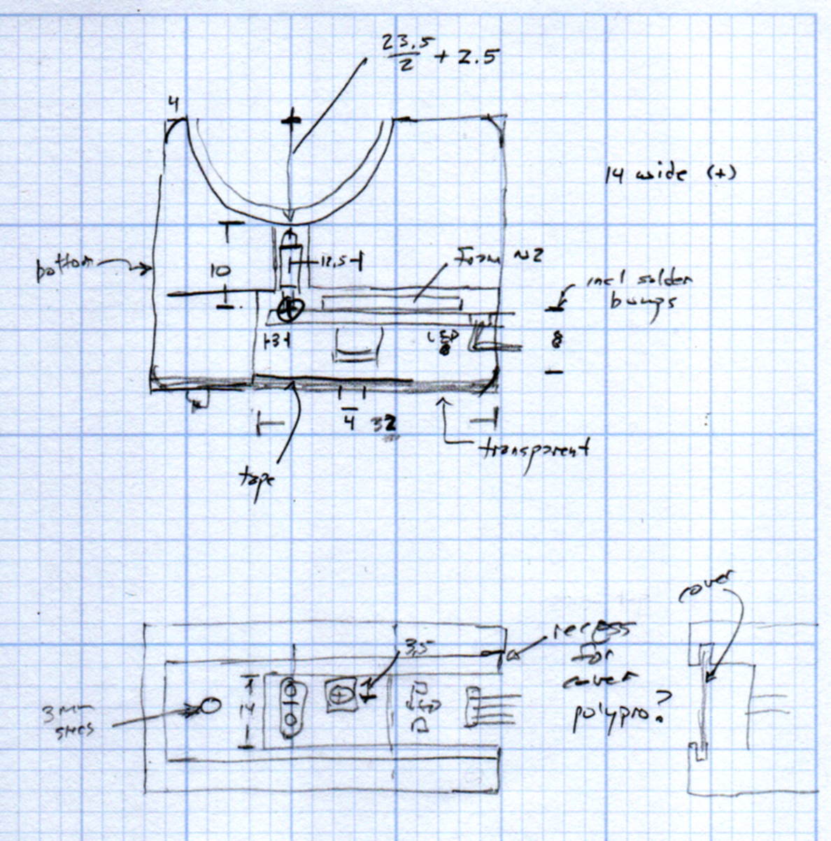
    The original doodles show a severely over-complexicated solution desperately searching for an actual problem:

    MPCNC Tool Length Probe - doodles
    MPCNC Tool Length Probe – doodles

    Putting a large flat pan at the end of a relatively long lever arm, with the pivot arranged to put the pan level at the switch actuation point, made sense at the time. Give the relatively small tools I expect to use, directly ramming them into the switch lever should work just as well.

    Putting all that complexity in harm’s way seemed like a Bad Idea when I sat down and looked at it in cold blood.

  • Finger Wrench

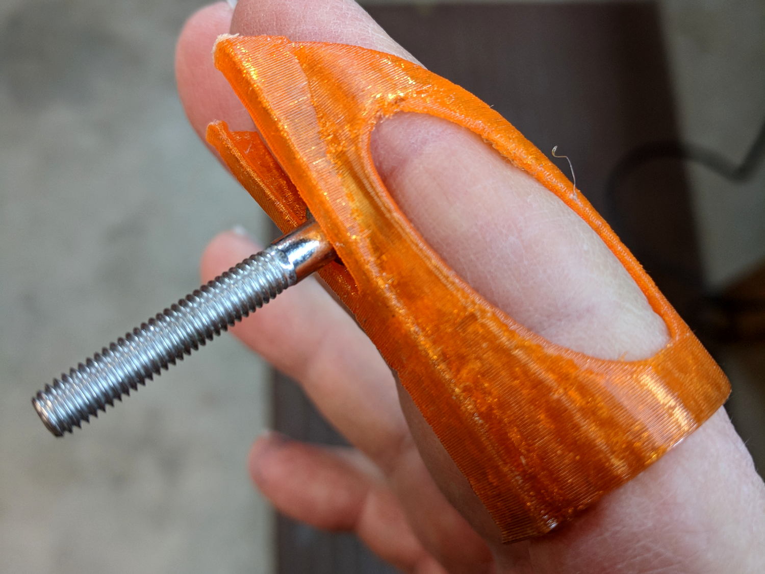
    A friend recommended a Finger Wrench and it looks useful, indeed:

    Finger Wrench
    Finger Wrench

    That’s a 10-32 socket head cap screw, on the large end of the screws I normally use.

    The orange PETG required a bit of smoothing around the overhangs, but should work well enough. The dark tinge near the bottom comes from the black filament I used for the MPCNC’s Z Axis sensor and won’t affect its operation in the least.

    Done with one perimeter thread and a 3 mm brim to glue down the bottom:

    Finger Wrench - Slic3r preview
    Finger Wrench – Slic3r preview

    That was easy …

  • MPCNC: Z Axis Upward Homing with Opto Proximity Sensor

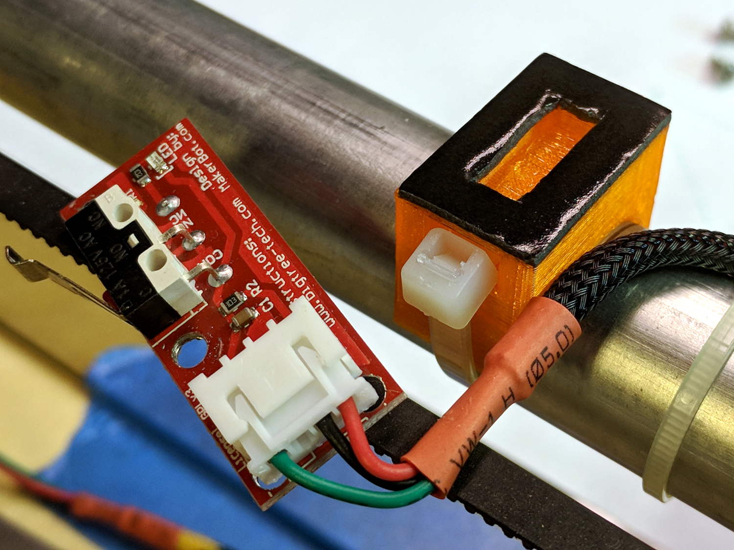
    Homing the MPCNC’s Z axis at the bottom end of its travel made no sense, but the Z stage lacks a convenient spot to mount / trigger a switch at the top of its travel, so this sufficed for initial tests & fiddling:

    MPCNC - Z min endstop
    MPCNC – Z min endstop

    The EMT rail carrying the switch moves downward, tripping the lever when it hits the MPCNC’s central assembly.

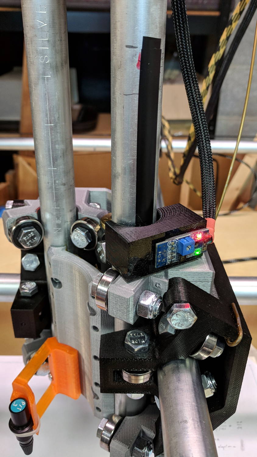
    Somewhat to my surprise, a TRCT5000-based optical proximity sensor (harvested from the Kenmore 158 Crash Test Dummy’s corpse) and a strip of black electrical tape work perfectly:

    MPCNC - Z Axis Opto Proximity Endstop
    MPCNC – Z Axis Opto Proximity Endstop

    The PCB wears a shiny new epoxy coat:

    MPCNC - Epoxy-coated Endstop - Opto Prox Sensor
    MPCNC – Epoxy-coated Endstop – Opto Prox Sensor

    I soldered the wires (harvested from the previous endstop) directly to the PCB, because the pinout isn’t the same and fewer connectors should be better.

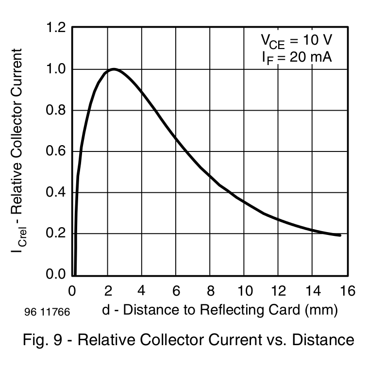
    The mount uses black PETG, rather than translucent orange, in hope of IR opacity, and wraps around the EMT rail at (roughly) the 2 mm standoff producing the peak response:

    IR Reflective Sensor module - TCRT5000 - response vs distance
    IR Reflective Sensor module – TCRT5000 – response vs distance

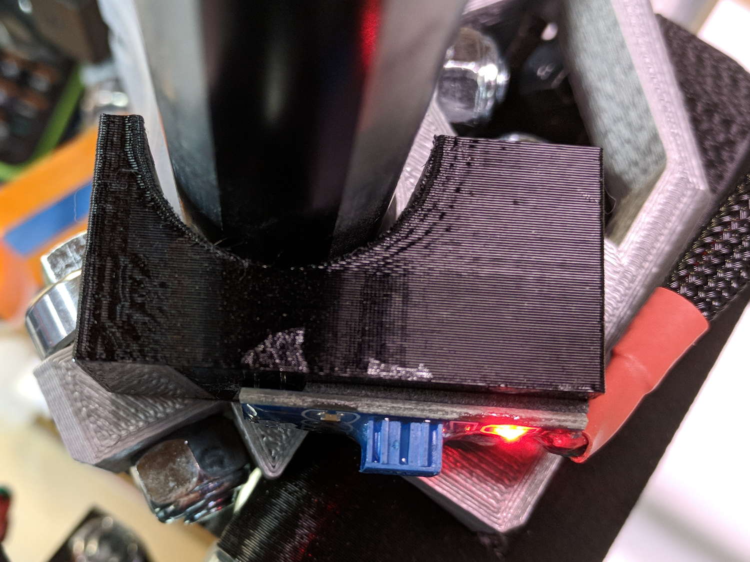
    In truth, I set the gap by eyeballometric guesstimation to make the entire mount arc sit equidistant from the EMT:

    MPCNC - Z Opto Prox Endstop - top view
    MPCNC – Z Opto Prox Endstop – top view

    The mount includes the 2 mm spacing around the EMT OD and puts the sensor tip flush with the arc OD, so it should be pretty close:

    TCRT5000 Z Axis Endstop Mount - solid model
    TCRT5000 Z Axis Endstop Mount – solid model

    A strip of 3M permanent tape, cut to clear the 608 bearings, affixes the mount to the MPCNC’s central assembly. The solid model now includes a midline reference notch, with a height rounded up to the next-highest multiple of 2.0 mm. It needs a loop to anchor the cable.

    The blue twiddlepot sets the comparator threshold midway between the response over black tape (incorrectly on = too low) and bare EMT (incorrectly off = too high), in the hope of noise immunity. The range spanned nearly half of the pot rotation, so I think it’s all good.

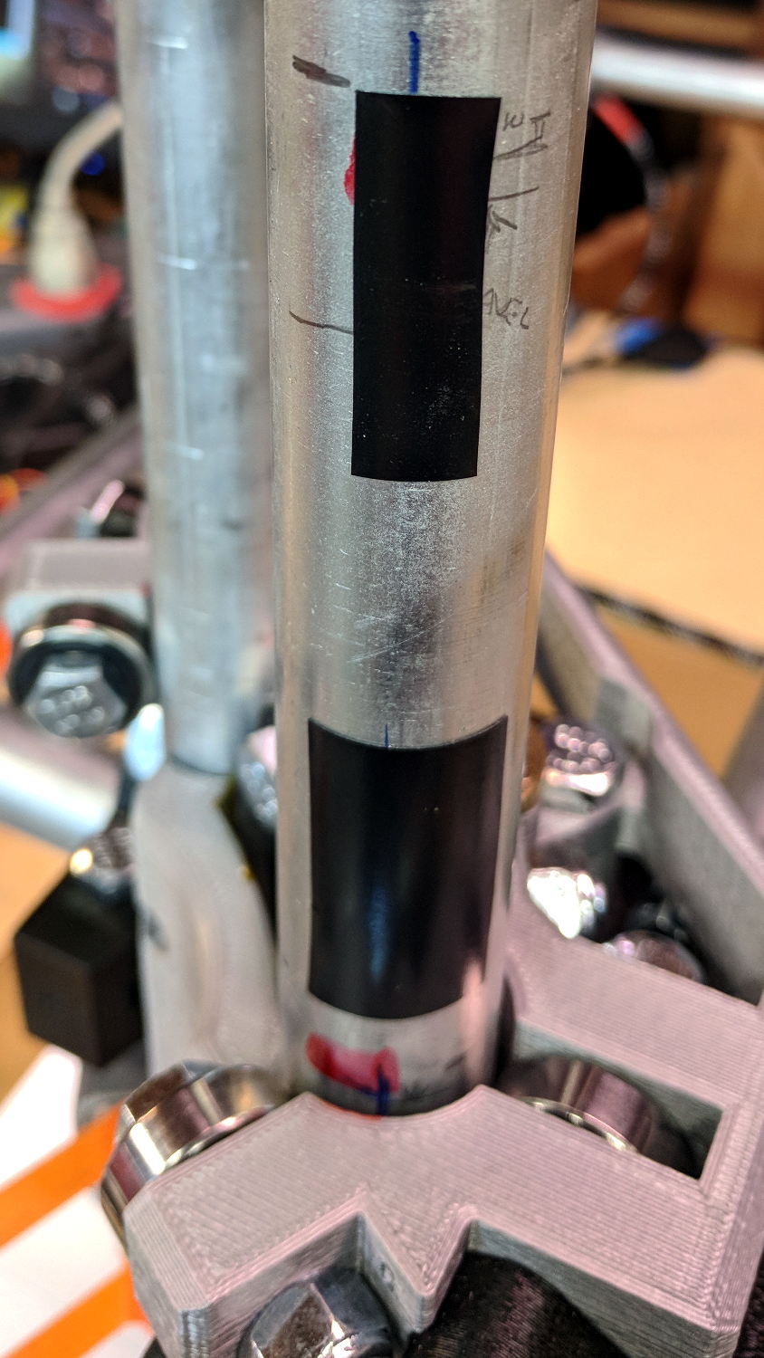
    The sensor doesn’t trip when the edge of the tape exactly meets its midline, which meant I had to trim a strip of tape to suit. As part of setting the twiddlepot, I shut off the Z axis motor and laid some test strips on the EMT:

    MPCNC - Z Axis Opto Prox Endstop - Test Tape
    MPCNC – Z Axis Opto Prox Endstop – Test Tape

    I spun the leadscrew with one hand, held the sensor with the other, twiddled the trimpot, trimmed the upper and lower ends of the tape, and generally had a fine time. The sensor responds equally well to a half-wide strip of tape (in the upper picture), with the distinct advantage of not encroaching on the 608 bearing tracks.

    The GRBL setup now homes Y and Z toward the positive end of their travel, with X still toward the negative end while a set of extension cables remains in transit around the planet.

    The OpenSCAD source code as a GitHub Gist:

    // TCRT5000 Z Axis Endstop Mount
    // Ed Nisley KE4ZNU – 2017-12-04
    /* [Build Options] */
    Layout = "Show"; // [Build, Show, Block]
    Section = true; // show internal details
    /* [Extrusion] */
    ThreadThick = 0.25; // [0.20, 0.25]
    ThreadWidth = 0.40; // [0.40]
    function IntegerMultiple(Size,Unit) = Unit * ceil(Size / Unit);
    /* [Hidden] */
    Protrusion = 0.01; // [0.01, 0.1]
    HoleWindage = 0.2;
    ID = 0;
    OD = 1;
    LENGTH = 2;
    /* [Sizes] */
    RailOD = 23.5; // actual rail OD
    OptoPCB = [32.5,14.2,1.6]; // prox sensor PCB
    ComponentHeight = 5.0; // max component height above PCB
    OptoSensor = [5.8,10.2,10.5]; // sensor head below PCB
    OptoOffset = 3.0; // sensor head center from PCB edge
    OptoRange = 2.0; // sensor to rail distance
    TapeThick = 1.0; // foam mounting tape
    WallThick = 4.0; // basic wall thickness
    Block = [WallThick + OptoRange + RailOD/2 + (OptoPCB[0] – OptoOffset),
    RailOD/2 + OptoRange + OptoSensor[2] – TapeThick,
    IntegerMultiple(OptoPCB[1] + 2*WallThick,2.0)]; // basic block shape
    echo(str("Block: ",Block));
    NumSides = 6*4;
    //- Adjust hole diameter to make the size come out right
    module PolyCyl(Dia,Height,ForceSides=0) { // based on nophead's polyholes
    Sides = (ForceSides != 0) ? ForceSides : (ceil(Dia) + 2);
    FixDia = Dia / cos(180/Sides);
    cylinder(r=(FixDia + HoleWindage)/2,h=Height,$fn=Sides);
    }
    //- Shapes
    // Main block constructed with PCB along X, opto sensor at Y=0
    module PCBBlock() {
    difference() {
    translate([-(WallThick + OptoRange + RailOD/2),
    (-Block[1] + RailOD/2 + OptoRange),
    -Block[2]/2])
    cube(Block,center=false);
    for (i=[-(RailOD/2 + OptoRange + WallThick),
    (OptoPCB[0] – OptoOffset)])
    translate([i,0,0])
    rotate([90,0,0]) rotate(45)
    cube([2*ThreadWidth,2*ThreadWidth,2*Block[2]],center=true);
    translate([0,(RailOD/2 + OptoRange),0])
    cylinder(d=(RailOD + 2*OptoRange),
    h=(Block[2] + 2*Protrusion),
    $fn=NumSides,center=true);
    rotate([90,0,0])
    cube(OptoSensor + [0,0,Block[1]],center=true);
    }
    }
    //- Build things
    if (Layout == "Block")
    PCBBlock();
    if (Layout == "Show") {
    translate([0,-(RailOD/2 + OptoRange),0])
    PCBBlock();
    color("Yellow",0.5)
    cylinder(d=RailOD,h=2*Block[2],$fn=NumSides,center=true);
    }
    if (Layout == "Build")
    translate([0,0,OptoSensor[2] – TapeThick])
    rotate([90,0,0])
    PCBBlock();

    The original doodles, including a bunch of ideas left on the cutting room floor:

    MPCNC Z Opto Proximity Sensor Endstop - doodles
    MPCNC Z Opto Proximity Sensor Endstop – doodles
  • MPCNC: Re-Improved Endstop Switch Mount

    As part of entombing the endstop PCBs in epoxy, I tweaked the switch mounts to (optionally) eliminate the screw holes and (definitely) rationalize the spacings:

    MPCNC MB Endstop Mount - No screws
    MPCNC MB Endstop Mount – No screws

    The sectioned view shows the cable tie slot neatly centered between the bottom of the switch terminal pit and the EMT rail, now with plenty of meat above the cable tie latch recess. The guide ramp on the other side has a more-better position & angle, too.

    A trial fit before dabbing on the epoxy:

    MPCNC - Endstop Mount for epoxy coating - trial fit
    MPCNC – Endstop Mount for epoxy coating – trial fit

    The 3M black foam tape works wonderfully well!

    After the epoxy cures, it’s all good:

    MPCNC - Epoxy-coated Endstop - Installed
    MPCNC – Epoxy-coated Endstop – Installed

    The OpenSCAD source code as a GitHub Gist:

    // MPCNC Endstop Mount for Makerbot PCB on EMT tubing
    // Ed Nisley KE4ZNU – 2017-12-04
    /* [Build Options] */
    Layout = "Show"; // [Build, Show, Block]
    Holes = false; // holes for switch screws
    Section = true; // show internal details
    /* [Extrusion] */
    ThreadThick = 0.25; // [0.20, 0.25]
    ThreadWidth = 0.40; // [0.40]
    function IntegerMultiple(Size,Unit) = Unit * ceil(Size / Unit);
    /* [Hidden] */
    Protrusion = 0.01; // [0.01, 0.1]
    HoleWindage = 0.2;
    ID = 0;
    OD = 1;
    LENGTH = 2;
    /* [Sizes] */
    RailOD = 23.5; // actual rail OD
    SwitchHeight = 8.0; // switch PCB distance from rail OD
    Strap = [5.5,50,2.0]; // nylon strap securing block to rail
    StrapHead = [8.2,3.0,5.5]; // recess for strap ratchet head
    Screw = [2.0,3.6,7.0]; // thread dia, head OD, screw length
    HoleOffset = [2.5,19.0/2]; // PCB mounting holes from PCB edge, rail center
    SwitchClear = [6.0,15,3.0]; // clearance around switch pins
    SwitchOffset = [6.0,0]; // XY center of switch from holes
    StrapHeight = (SwitchHeight – SwitchClear[2])/2; // strap center from rail
    Block = [16.4,26.0,RailOD/2 + SwitchHeight]; // basic block shape
    //- Adjust hole diameter to make the size come out right
    module PolyCyl(Dia,Height,ForceSides=0) { // based on nophead's polyholes
    Sides = (ForceSides != 0) ? ForceSides : (ceil(Dia) + 2);
    FixDia = Dia / cos(180/Sides);
    cylinder(r=(FixDia + HoleWindage)/2,h=Height,$fn=Sides);
    }
    //- Shapes
    // Main block constructed centered on XY with Z=0 at top of rail
    module PCBBlock() {
    difference() {
    translate([-Block[0]/2,-Block[1]/2,-RailOD/2])
    cube(Block,center=false);
    translate([(SwitchOffset[0] + HoleOffset[0] – Block[0]/2),
    SwitchOffset[1],
    (SwitchHeight – SwitchClear[2]/2 + Protrusion/2)])
    cube(SwitchClear + [0,0,Protrusion],center=true);
    if (Holes)
    for (j=[-1,1])
    translate([HoleOffset[0] – Block[0]/2,j*HoleOffset[1],(Block[2]/2 – Screw[LENGTH])])
    rotate(180/6)
    if (true) // true = loose fit
    PolyCyl(Screw[ID],Screw[LENGTH] + Protrusion,6);
    else
    cylinder(d=Screw[ID],h=Screw[LENGTH] + Protrusion,$fn=6);
    translate([0,0,StrapHeight])
    cube(Strap,center=true);
    translate([0, // strap head recess
    (Block[1]/2 – StrapHead[1]/2 + Protrusion),
    StrapHeight – Strap[2]/2 + StrapHead[2]/2])
    cube(StrapHead + [0,Protrusion,0],center=true);
    StrapAngle = atan((StrapHeight + RailOD/4)/Strap[2]); // a reasonable angle
    echo(str("Strap Angle: ",StrapAngle));
    translate([0,-(Block[1]/2 – Strap[2]/(2*sin(StrapAngle))),StrapHeight])
    rotate([StrapAngle,0,0])
    translate([0,-Strap[1]/2,0])
    cube(Strap,center=true);
    if (Section)
    translate([Block[0]/2,0,0])
    cube(Block + [0,2*Protrusion,2*Block[2]],center=true);
    }
    }
    module Mount() {
    difference() {
    translate([0,0,RailOD/2])
    PCBBlock();
    rotate([0,90,0])
    cylinder(d=RailOD,h=3*Block[0],center=true);
    }
    }
    //- Build things
    if (Layout == "Show") {
    Mount();
    color("Yellow",0.5)
    rotate([0,90,0])
    cylinder(d=RailOD,h=3*Block[0],center=true);
    }
    if (Layout == "Block")
    PCBBlock();
    if (Layout == "Build")
    translate([0,0,Block[2]])
    rotate([180,0,0])
    Mount();
  • MPCNC: Epoxy-Coated Endstop Switches

    Using 3D printer style endstop switches has the advantage of putting low-pass filters (i.e. caps) at the switches, plus adding LED blinkiness, but it does leave the +5 V and Gnd conductors hanging out in the breeze. After mulling over various enclosures, it occured to me I could just entomb the things in epoxy and be done with it.

    The first step was to get rid of the PCB mounting screws and use 3M permanent foam tape:

    MPCNC - Epoxy-coated Endstop - Adhesive Tape
    MPCNC – Epoxy-coated Endstop – Adhesive Tape

    Get all the switches set up and level, mix up 2.8 g of XTC-3D (because I have way too much), and dab it on the switches until all the exposed conductors have at least a thin coat:

    MPCNC - Epoxy-coated Endstop - Installed
    MPCNC – Epoxy-coated Endstop – Installed

    You should use a bit more care than I: the epoxy can creep around the corner of the switch and immobilize the actuator in its relaxed position. Some deft X-Acto knife work solved the problem, but only after firmly smashing the X axis against the nonfunctional switch.

    Epoxy isn’t a particularly good encapsulant, because it cures hard and tends to crack components off the board during temperature extremes. These boards live in the basement, cost under a buck, and I have plenty of spares, so let’s see what happens.

    At least it’s now somewhat more difficult to apply a dead short across the Arduino’s power supply, which comes directly from a Raspberry Pi’s USB port.

  • MPCNC: A4988 Driver Microstep Waveforms

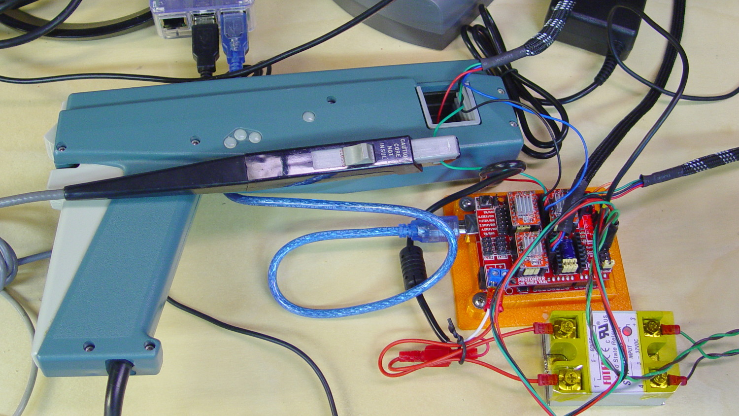
    I measured stepper motor winding current with a pair of Tek Hall effect probes for future reference.

    MPCNC - X Axis current measurement setup - overview
    MPCNC – X Axis current measurement setup – overview

    The pistol-shaped A6303 measures up to 100 A, so it’s grossly overqualified for the job. The much smaller A6302 goes to 20 A and is definitely the right hammer. The single-trace pix show 200 mA/div.

    I’m using the default 12 V6 A MPCNC stepper power supply, with A4988 stepper driver boards on the Protoneer CNC Shield atop a knockoff Arduino UNO running GRBL firmware. The blue USB cable goes off to a Raspberry Pi running minicom for manual control.

    All the pix use the same G-Code command: G1 X2.4 F180. Running at 180 mm/min = 3 mm/s eliminates pretty nearly all visible acceleration.

    Each picture requires:

    • m9 to disable stepper power
    • Remove X axis A4988 driver board
    • Set jumpers to select new microstep mode
    • Reinstall driver board
    • Change GRBL $100 step/mm setting to match jumpers
    • Ctrl-X = reset GRBL
    • $x = unlock
    • m8 = enable power
    • Enable scope trigger (single-trigger mode)
    • g1x2.4f180 motion for next image
    • x0 = return to origin

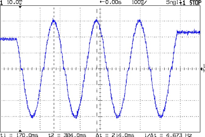
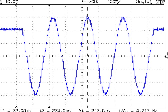
    With the A4988 stepper driver in 16:1 microstep mode:

    MPCNC g1x2.4f180 - 16 ustep - 200 mA-div
    MPCNC g1x2.4f180 – 16 ustep – 200 mA-div

    Notice how some of the microsteps aren’t particularly crisp, notably around the zero crossings. I think the relatively low 12 V supply doesn’t give the A4988 enough control authority to boss the current around, resulting in difficulty holding the current setpoint, even at low speed:

    MPCNC X 10mm 60mm-s 500mA-div
    MPCNC X 10mm 60mm-s 500mA-div

    More on that problem in a while.

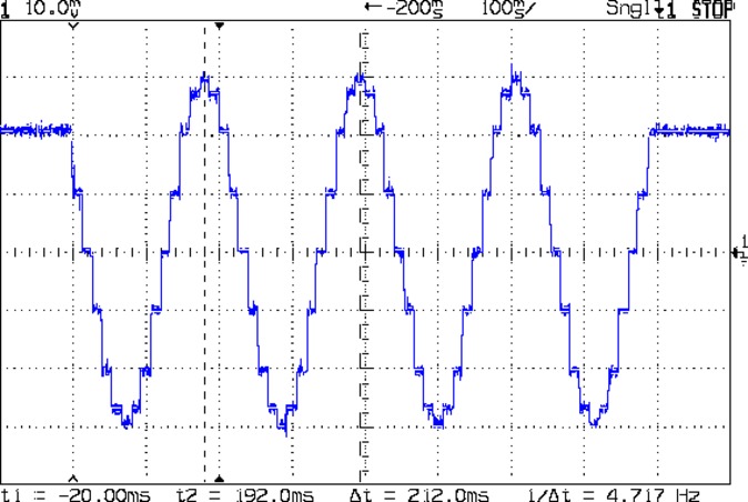
    In 8:1 microstep mode:

    MPCNC g1x2.4f180 - 8 ustep - 200 mA-div
    MPCNC g1x2.4f180 – 8 ustep – 200 mA-div

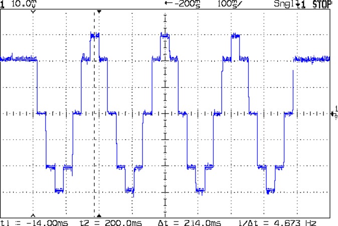
    In 4:1 microstep mode:

    MPCNC g1x2.4f180 - 4 ustep - 200 mA-div
    MPCNC g1x2.4f180 – 4 ustep – 200 mA-div

    In 2:1 microstep mode:

    MPCNC g1x2.4f180 - 2 ustep - 200 mA-div
    MPCNC g1x2.4f180 – 2 ustep – 200 mA-div

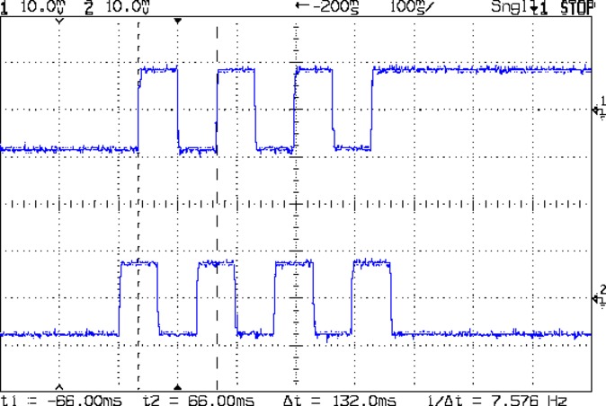
    And, a rarity in modern times, both windings at 500 mA/div in full step mode:

    MPCNC g1x2.4f180 - 1 ustep - dual 500 mA-div
    MPCNC g1x2.4f180 – 1 ustep – dual 500 mA-div

    The A4988 driver reduces the peak current to 1/√2 of the stepped sine wave peak to maintain the same average power dissipation and torque. For reasons I cannot explain, the full-step move takes far less time than the others; it must have something to do with how GRBL computes the average speed. It sounds like a robotic woodpecker hammering on the MPCNC’s frame, so I flipped back to 16:1 microstep mode after taking that picture.

    Now I can refer to these from elsewhere …