Ed Nisley's Blog: Shop notes, electronics, firmware, machinery, 3D printing, laser cuttery, and curiosities. Contents: 100% human thinking, 0% AI slop.
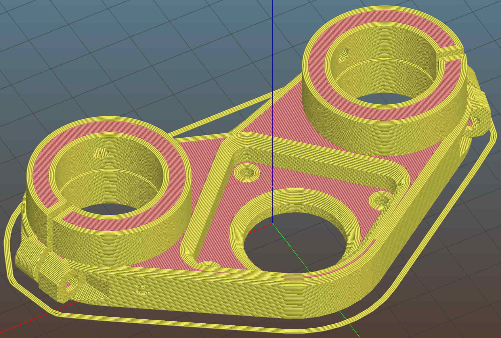
It adds a festive touch when done up in orange PETG:
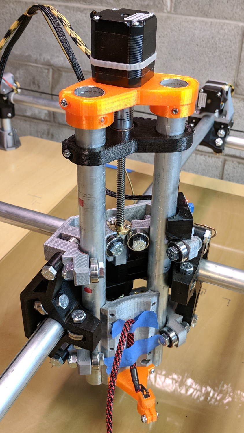
MPCNC – Reinforced Z Motor Mount
The attentive reader will note the missing head of the screw anchoring the mount to the left Z rail. Apparently a #32 drill was a bit too small to let the randomly chosen self-tapping screws thread themselves into EMT; they probably anchored a PCB to the plastic case of a long-forgotten lump of consumer electronics.
It should last long enough for something else to let go …
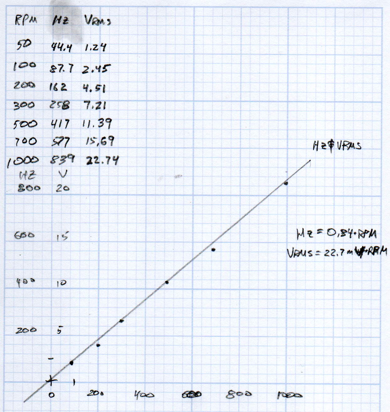
KL17H248-15-4A stepper motor – Back EMF vs RPM – data
Maybe the only questions I ask are ones with linear solutions?
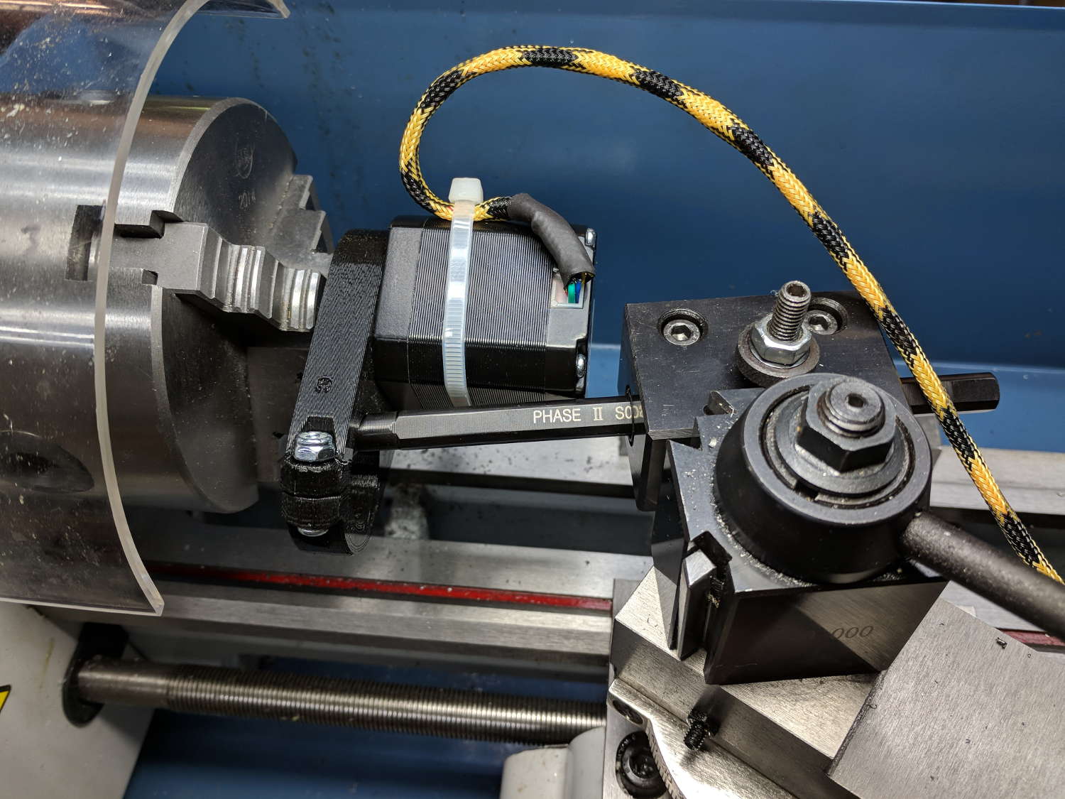
Anyhow, the data comes from the Z-axis motor in the lathe:
Stepper back EMF test setup
Scary-looking, but reasonably safe. The chuck holds the motor shaft so it’s not going anywhere, the boring bar prevents any rotation, and the motor bearings do exactly what they’re supposed to. Shorting the motor leads would definitely put a hurt on the PLA frame, so I didn’t do that.
The scope sat on the floor beside the lathe, capturing waveforms and doing calculations:
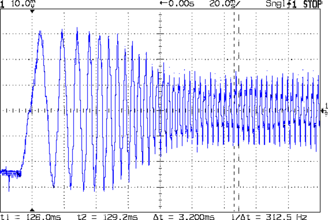
Motor Back EMF – 500 RPM
Some waveforms look bent:
Motor Back EMF – 300 RPM
I asked the scope to measure the RMS voltage, rather than the peak, because it’s less sensitive to distortions.
Each winding produces one electrical cycle across four mechanical full steps, with the windings in quadrature. One shaft revolution thus produces 200 / 4 = 50 electrical cycles, so converting from shaft RPM into electrical cycles/s goes a little something like this:
So the shaft turns at 375 RPM when the X axis moves at 12 k mm/min, with each motor generating 8.5 Vrms = 12 Vpk of back EMF.
The MPCNC wires the two motors on each axis in series, so the 24 V power supply faces 24 V of back EMF (!) from both motors, leaving exactly nothing to push the winding current around. Because the highest EMF occurs at the zero crossing points of the (normal) winding current, I think the current peaks now occur there, with the driver completely unable to properly shape the current waveform.
What you see in the scope shot is what actually happens: the current stabilizes at a ragged square-ish wave at maybe 300 mA (plus those nasty spikes). More study is needed.
The MPCNC uses a DW660 Cutout tool as a low-cost spindle for tools with 1/8 and 1/4 inch shanks. It features a tool-free “collet grip” to twist the collet nut against the shaft lock, which is convenient for a hand tool and not so much for a CNC spindle: I find it difficult to get two hands into the MPCNC setup with the proper orientation to push-and-hold two locking buttons, while applying enough torque to twist the collet nut:
DW660 – collet grip
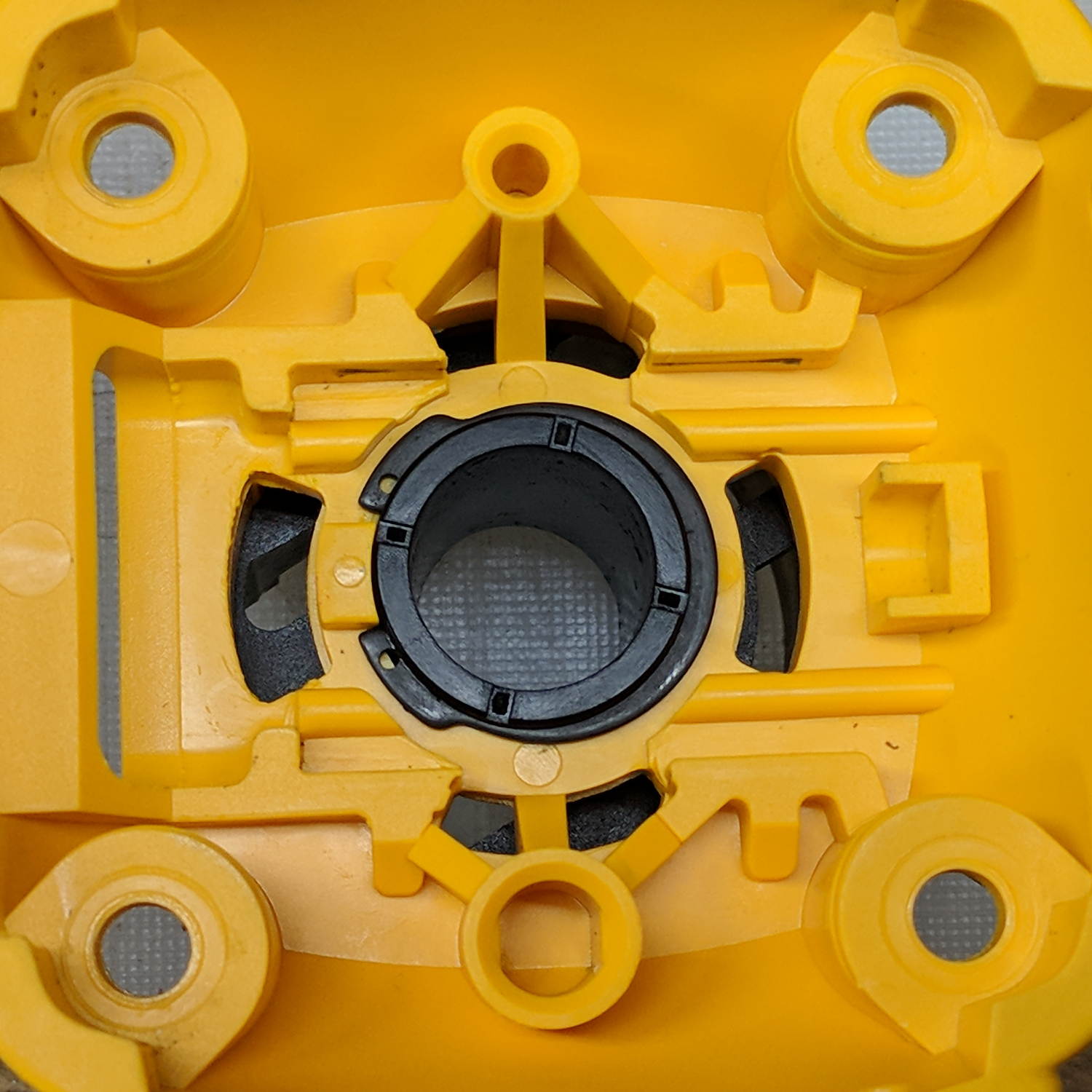
Fortunately, it’s easy enough to remove the collet grip. Remove the collet nut, unscrew the four screws holding the yellow snout in place, then pull the snout straight off to reveal the spindle lock plate:
DW660 – nose cap interior
Capture the spring, slide the spindle lock plate out to expose the snap ring (a.k.a. Jesus clip) holding the collet grip in place:
DW660 – collet grip snap ring
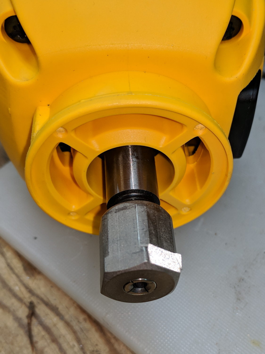
Remove the snap ring, make the appropriate remark, pull the collet grip out of the snout, reassemble the snout in its One Correct Orientation, and you’re done:
DW660 – collet grip removed
The retroreflective tape snippet let my laser tachometer report a top speed over 29 k rpm, pretty close to the advertised 30 k rpm.
If one were fussy, one would 3D print a thing to cover the snout’s open end:
DW660 – snout cover
The original snap ring holds it in place and the fancy pattern comes from octogram spiral infill on the bottom.
The collet nut fits either a 5/8 inch or 16 mm wrench, both of which stick out to the side far enough for a convenient hold while pressing the shaft lock button.
When I wired up the MPCNC’s tool length probe, I planned to reinforce the wiring with a dab of epoxy. What I didn’t notice in my enthusiasm, alas, was the opening from the rear to the front in each pin slot:
Epoxied connector – rear
Which let the epoxy flow completely through the connector:
Epoxied connector – front
So I cut the mess off and applied heatstink tubing on each wire, just like I should have in the first place.
Now you know the rest of the story …
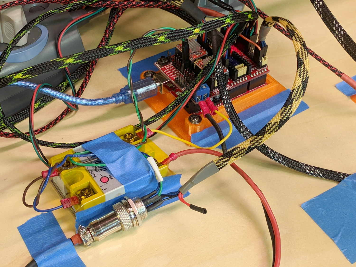
I really dislike pin headers as cable connectors, but that’s what the Protoneer CNC board uses:
MPCNC – Protoneer Wiring – SSR
It’ll be Good Enough if I don’t do anything else particularly stupid.
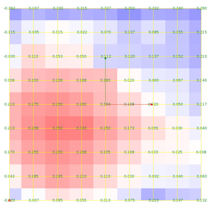
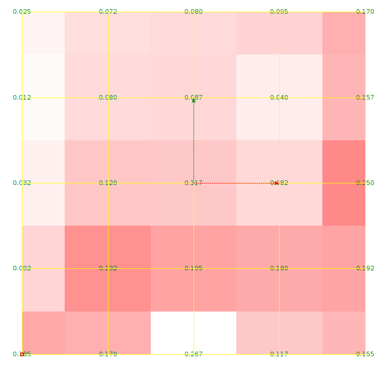
The first height map looks like a mountain sproinged right up through the glass:
ProbeArray-Glass-50
More red-ish means increasing height, more blue-ish means increasing depth, although you can only see the negative signs along the left edge.
The Z axis leadscrew produces 400 step/mm for a “resolution” of 0.0025 mm. The bCNC map rounds to three places, which makes perfect sense to me; I doubt the absolute accuracy is any better than 0.1 mm on a good day with fair skies and a tailwind.
The peak of the mountain rises 0.35 mm above the terrain around it, so it barely counts as a minor distortion in the glass sheet. Overall, however, there’s a 0.6 mm difference from peak to valley, which would be enough to mess up a rigidly held pen tip pretty badly if you assumed the glass was perfectly flat and precisely aligned.
Rotating the glass around the X axis shows a matching, albeit shallower, dent on the other side:
ProbeArray-Glass-flip-50-2018-01-05
For all its crudity, the probe seems to be returning reasonable results.
The obvious question: does it return consistent results?
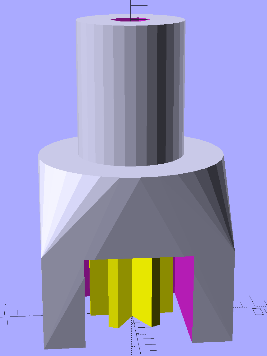
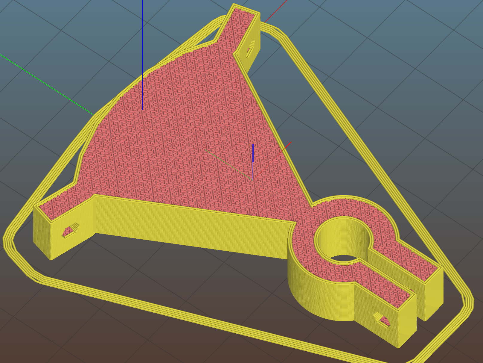
A little support pillar makes a printable holder for a small tactile pushbutton:
Z Axis Height Probe – solid model
A(n) 0-80 brass washer epoxied atop the butt end of a P100-B1 pogo pin keeps the pin from falling out and provides a flat button pusher:
MPCNC – Simple Z probe – push plate
With the epoxy mostly cured, ease the pin off the tape, flip the whole affair over, shove the switch into position, realign vertically with point down, then let the epoxy finish curing with the washer held in place against the switch to ensure good alignment:
MPCNC – Simple Z probe – epoxy curing
The brass tube ID is a sloppy fit around the pogo pin, but it’s also many pin diameters long and the position error isn’t worth worrying about.
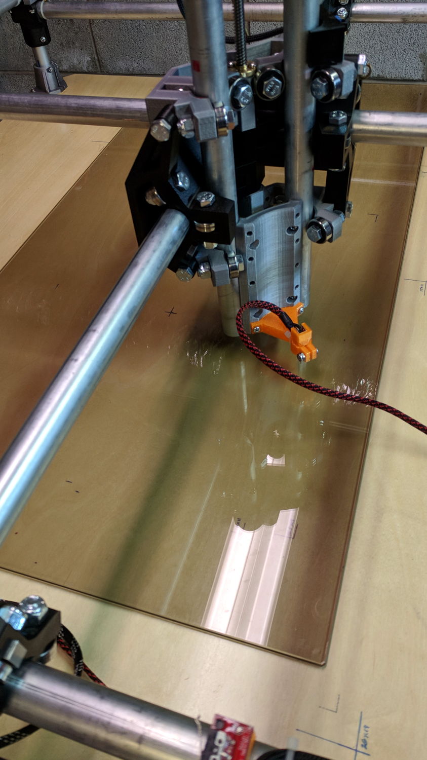
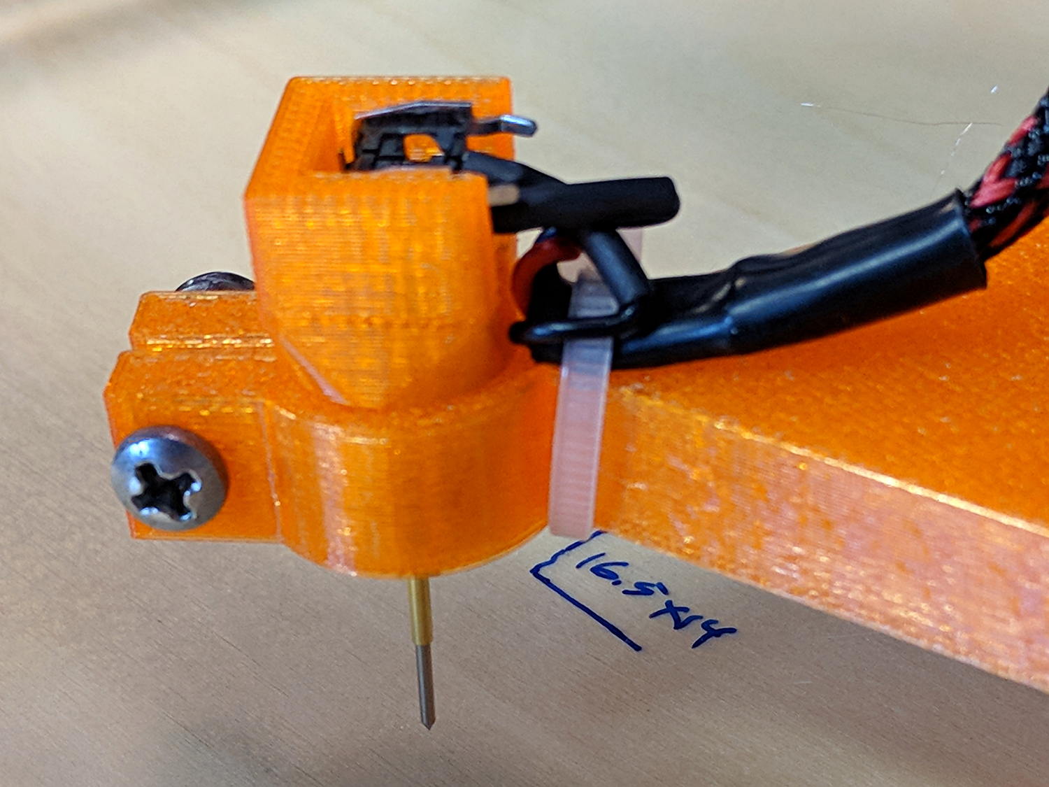
Solder a cable, clamp it in the pen holder, attach to tool holder:
MPCNC – Simple Z probe – installed
The pogo pin provides half a dozen millimeters of compliance, letting the initial probe speed be much higher than the tactile pushbutton’s overshoot could survive, after which a low-speed probe produces a consistent result.
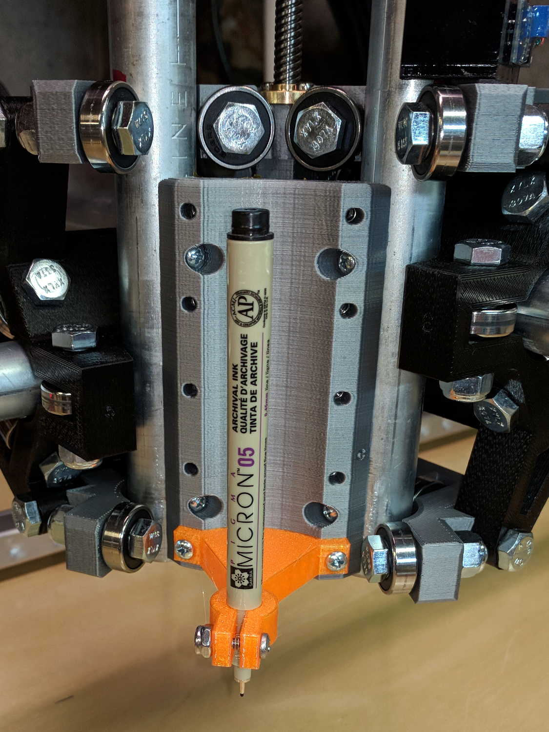
The pen body seats atop the holder, with its narrower snout inside the clamp, giving positive control of the point position:
MPCNC – Sakura in pen adapter
Unfortunately, should one forget to zero the pen tip to the paper surface before starting a plot, Bad Things happen to good tips:
MPCNC – Sakura pen – crushed tip
The holder really needs at least a few millimeters of compliance, as a fiber-tip pen makes a fairly delicate tool not intended for applying much force at all to anything.