The Smell of Molten Projects in the Morning

Ed Nisley's Blog: Shop notes, electronics, firmware, machinery, 3D printing, laser cuttery, and curiosities. Contents: 100% human thinking, 0% AI slop.

Tag: MPCNC

Pimping and using a Mostly Printed CNC Machine

  • MPCNC – Autolevel Probe, Collet Edition

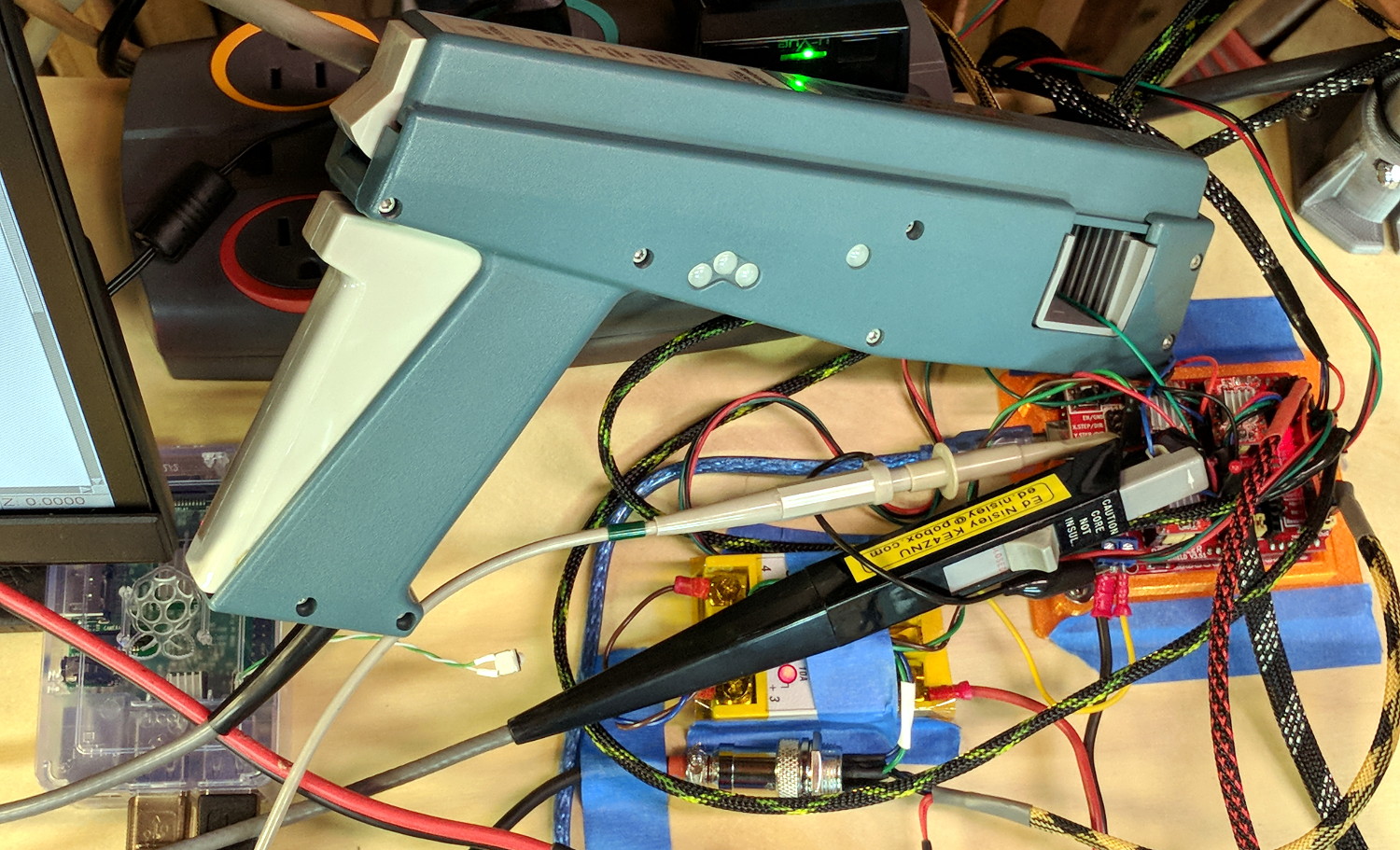
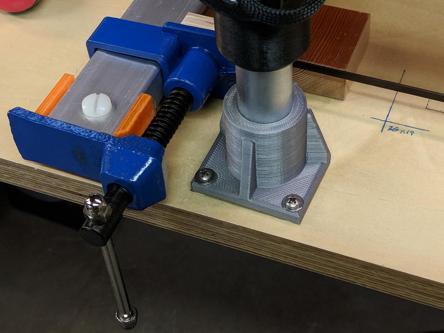
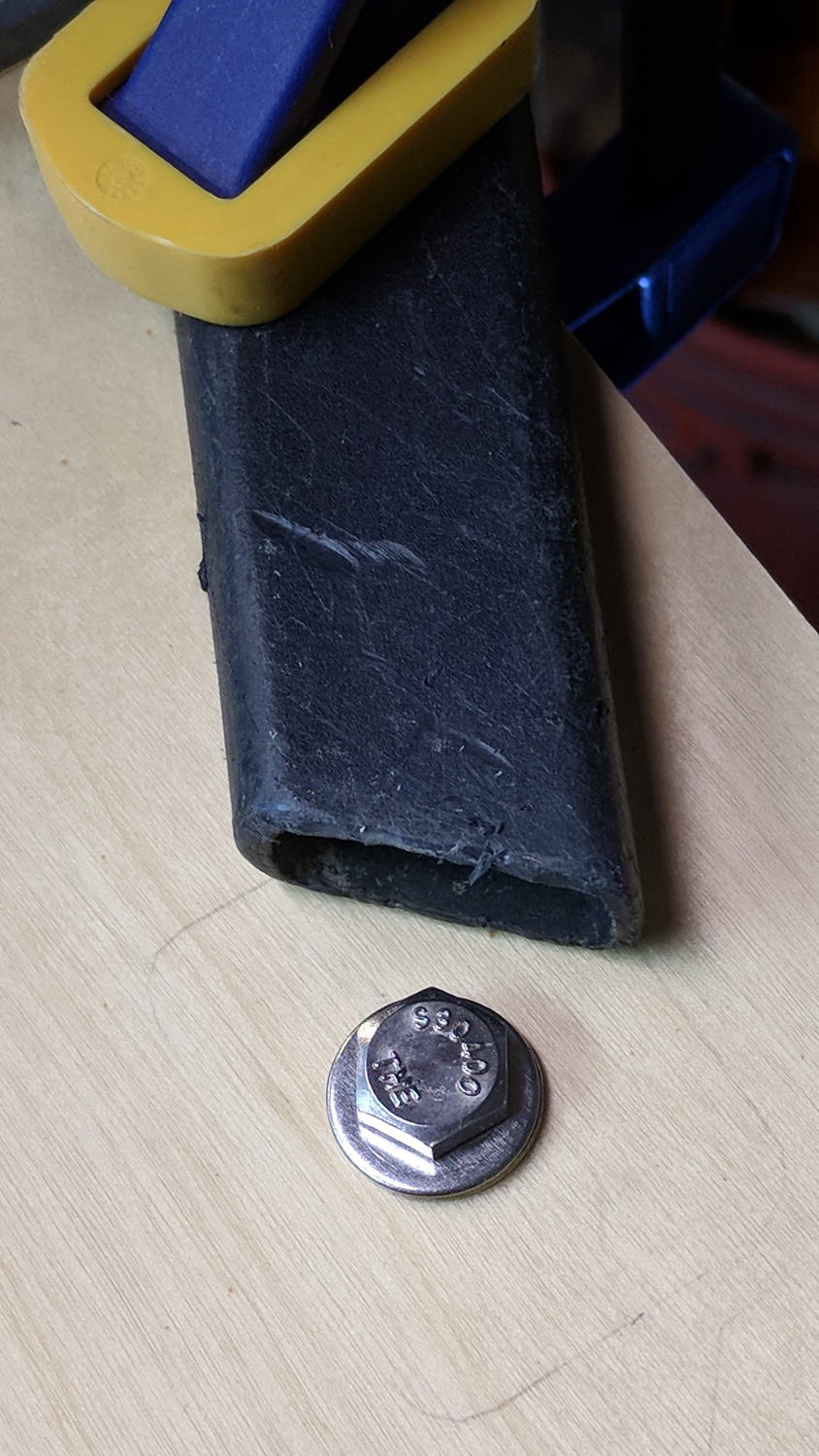
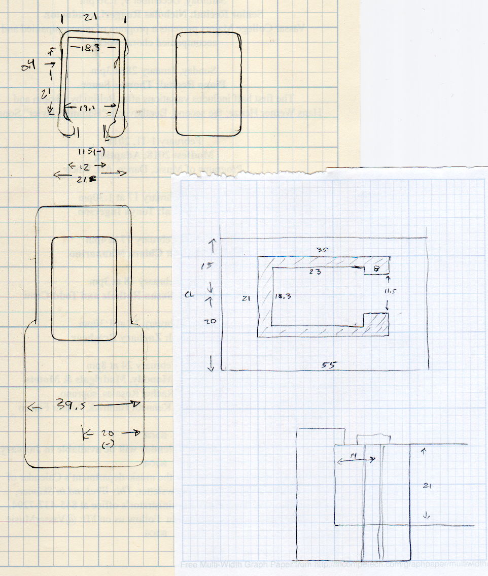
    Although putting a Z-axis height probe in a rigid pen holder worked well enough, it’d be handy to have a probe with a stud suitable for clamping in the DW660 spindle (with the power off!):

    MPCNC - Z probe - DW660 - 0.25 collet
    MPCNC – Z probe – DW660 – 0.25 collet

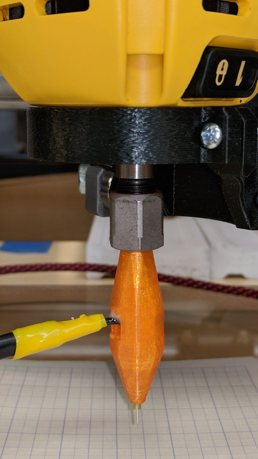
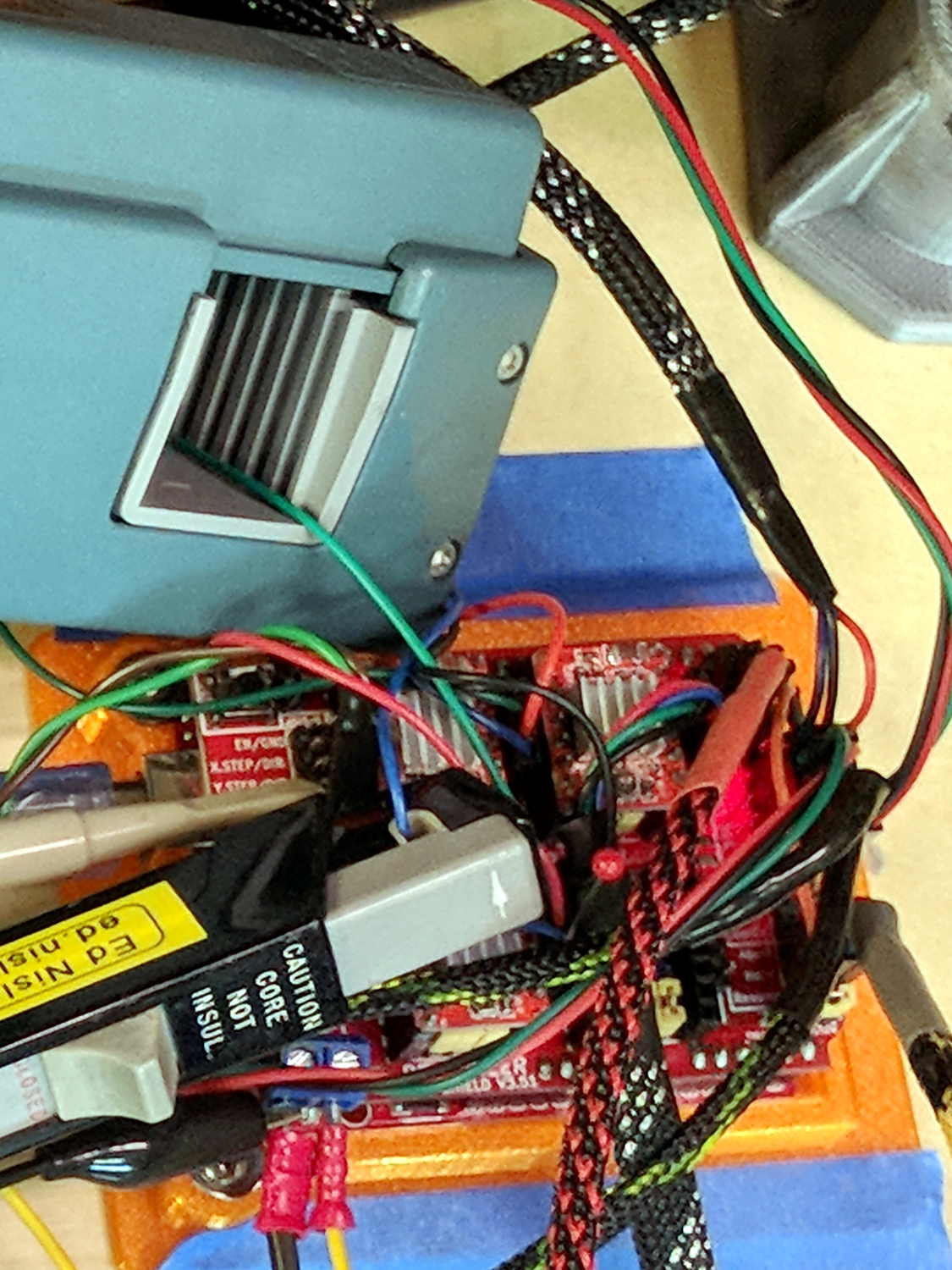
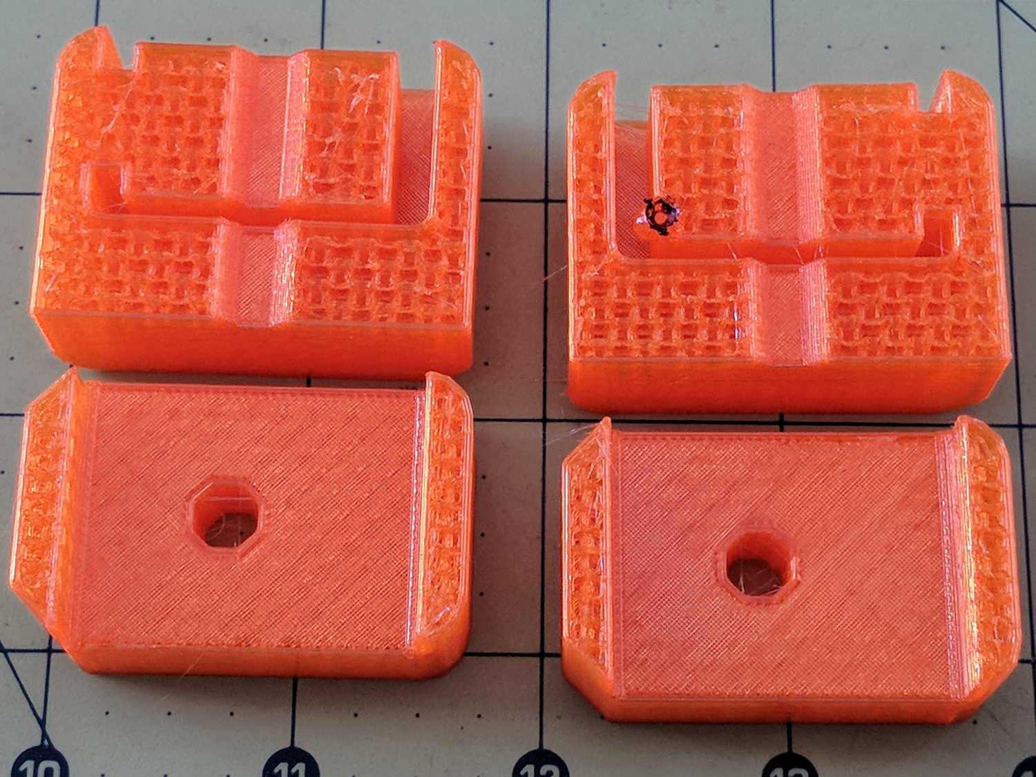
    Inside, it uses the same pushbutton and pogo pin as the pen holder design, with a similar brass tube around the pogo pin.

    There’s a conspicuous lack of good wire management; we all know where those wires will snap. In practice, you’d secure it to the DW660 power cord, way up on top, to eliminate most of the flexing. Still, it wants better strain relief than its gets from those heatstink tubes.

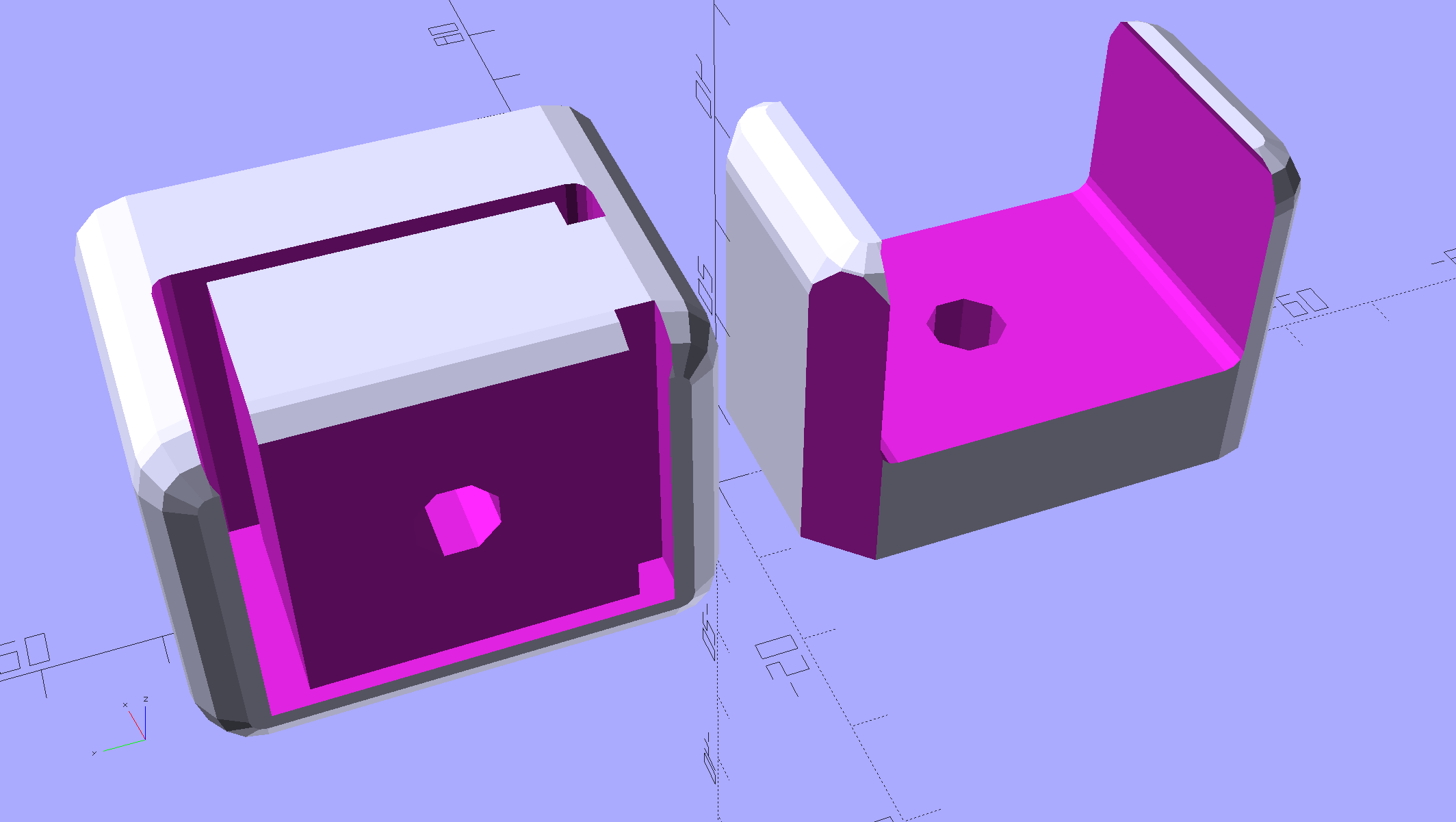
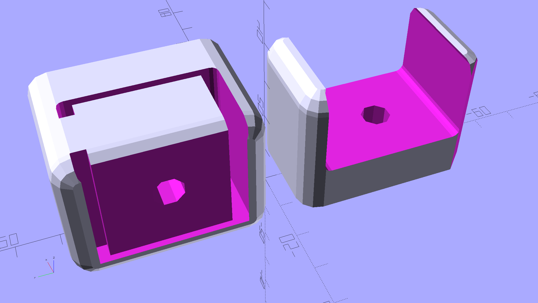
    The solid model looks like a weaving shuttle:

    MPCNC - Autolevel probe - collet - Slic3r preview
    MPCNC – Autolevel probe – collet – Slic3r preview

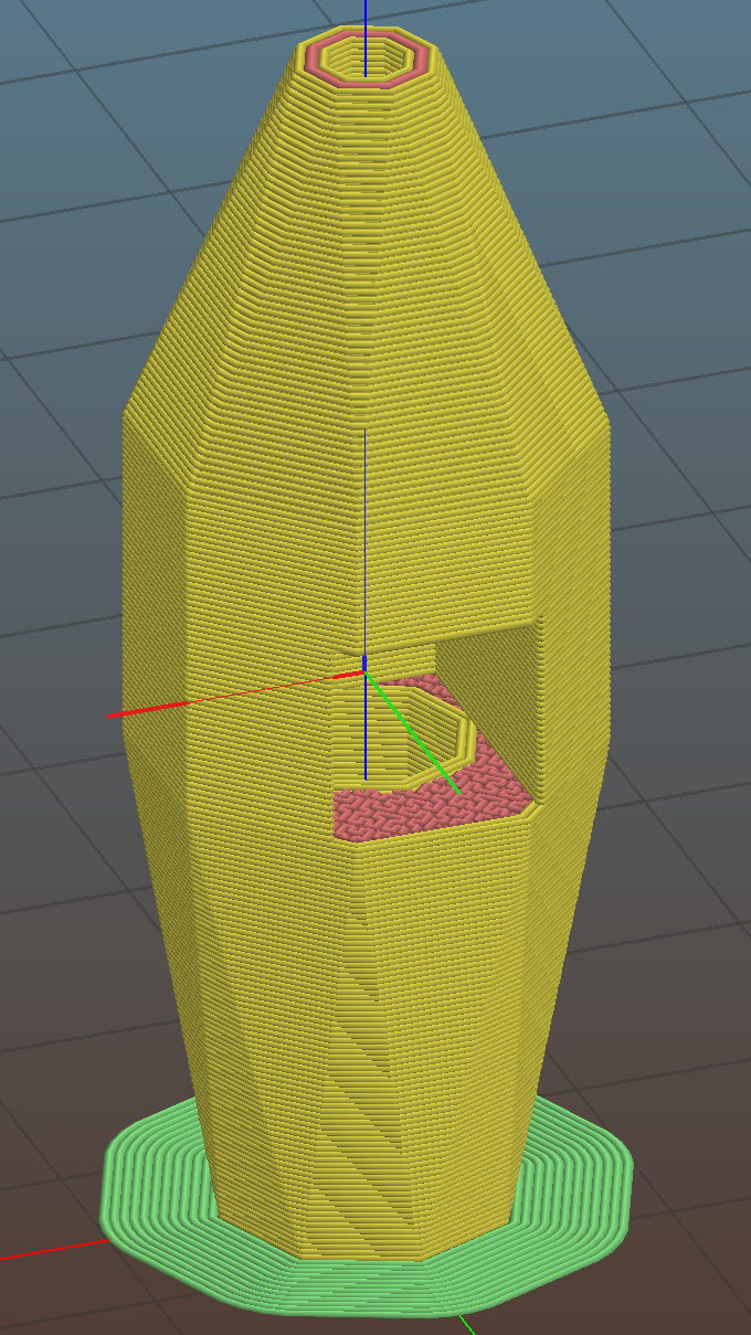
    It’s sitting upside-down in a 5 mm brim for more platform adhesion.

    The next one will have a 1/8 inch stud to fit the DW660’s other collet and shorten the top by 3/8 inch, because I want the rod inserted three diameters for stability. The bottom can’t get much shorter, because the pogo pin determines the switch-to-tip distance. Maybe a simple membrane switch will work well enough?

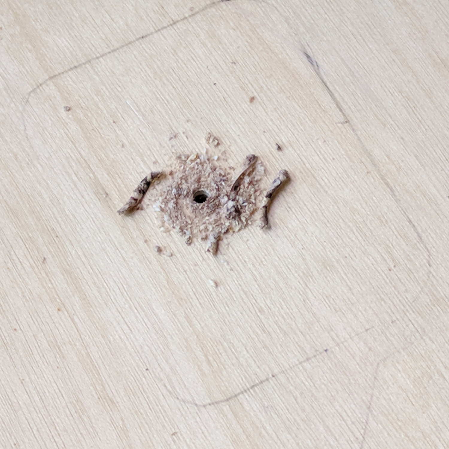
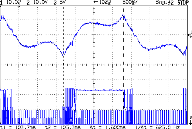
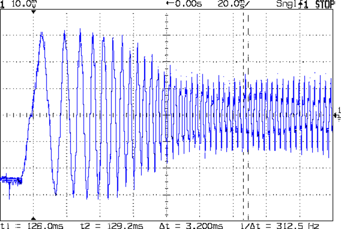
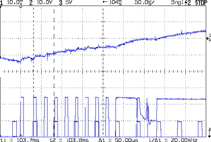
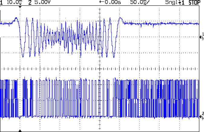
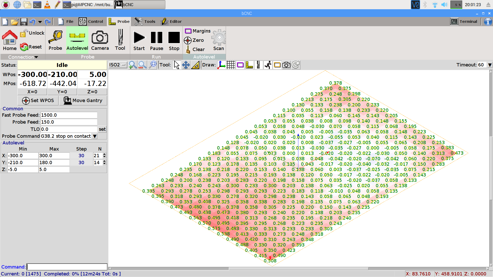
    You can see the depression in the glass sheet pretty clearly in a bCNC Autolevel scan on 30 mm centers (clicky for more dots):

    bCNC - Probe Array - 600x390 30 mm OC - ISO2
    bCNC – Probe Array – 600×390 30 mm OC – ISO2

    The OpenSCAD source code as a GitHub Gist:

    // MPCNC Z Axis Height Probe for router collet
    // Ed Nisley KE4ZNU – 2018-02-14
    Layout = "Build"; // Build, Show
    Section = false;
    /* [Extrusion] */
    ThreadThick = 0.25; // [0.20, 0.25]
    ThreadWidth = 0.40; // [0.40]
    /* [Hidden] */
    Protrusion = 0.1; // [0.01, 0.1]
    HoleWindage = 0.2;
    inch = 25.4;
    function IntegerMultiple(Size,Unit) = Unit * ceil(Size / Unit);
    ID = 0;
    OD = 1;
    LENGTH = 2;
    //- Adjust hole diameter to make the size come out right
    module PolyCyl(Dia,Height,ForceSides=0) { // based on nophead's polyholes
    Sides = (ForceSides != 0) ? ForceSides : (ceil(Dia) + 2);
    FixDia = Dia / cos(180/Sides);
    cylinder(r=(FixDia + HoleWindage)/2,h=Height,$fn=Sides);
    }
    /* [Switch] */
    SwitchBody = [7.8,6.8,7.0]; // PCB mount hardware extends infinitely to +Y
    SwitchButton = [3.5,5.0,1.0]; // OD allows some clearance
    SwitchClear = 5.0; // room for pad atop probe rod
    SwitchZ = SwitchBody.z + SwitchButton.z + SwitchClear;
    Sleeve = [1.5,2.5,15.0]; // tube around pogo pin
    ShankOD = 0.25 * inch; // rod into tool collet
    /* [Hidden] */
    WallThick = 3.0; // basic wall & floor thickness
    ProbeBody = [Sleeve[OD],
    2*WallThick + sqrt(pow(SwitchBody.x,2) + pow(SwitchBody.y,2)),
    3*ShankOD + SwitchZ + Sleeve[LENGTH]];
    echo(str("Probe Body: ",ProbeBody));
    NumSides = 2*4;
    //—–
    // Define shapes
    module Switch() {
    union() {
    translate([0,0,SwitchBody.z/2])
    cube(SwitchBody,center=true);
    translate([0,ProbeBody[OD]/2 – SwitchBody.y/2,(SwitchBody.z + SwitchButton.z)/2])
    cube([SwitchBody.x,ProbeBody[OD],SwitchBody.z + SwitchButton[LENGTH]],center=true);
    translate([0,0,SwitchBody.z])
    PolyCyl(SwitchButton[OD],SwitchButton[LENGTH] + SwitchClear,6);
    }
    }
    module ProbeHolder() {
    difference() {
    hull() {
    PolyCyl(Sleeve[OD] + 6*ThreadWidth,Protrusion,NumSides);
    translate([0,0,Sleeve.z])
    rotate(180/8)
    PolyCyl(ProbeBody[OD],SwitchZ,NumSides);
    translate([0,0,Sleeve.z + SwitchZ + 3*ShankOD – Protrusion])
    PolyCyl(ShankOD + 10*ThreadWidth,Protrusion,NumSides);
    }
    translate([0,0,SwitchZ + Sleeve[LENGTH]])
    rotate([0,180,0])
    Switch();
    translate([0,0,-Protrusion])
    PolyCyl(Sleeve[OD],Sleeve[LENGTH] + 2*Protrusion,NumSides);
    translate([0,0,Sleeve.z + SwitchZ – Protrusion])
    PolyCyl(ShankOD,3*ShankOD + 2*Protrusion,NumSides);
    if (Section)
    translate([ProbeBody[OD]/2,0,ProbeBody[LENGTH]/2])
    cube([ProbeBody[OD],2*ProbeBody[OD],ProbeBody[LENGTH] + 2*Protrusion],center=true);
    }
    }
    //—–
    // Build it
    if (Layout == "Show")
    ProbeHolder();
    if (Layout == "Build") {
    translate([0,0,ProbeBody.z])
    rotate([0,180,0])
    ProbeHolder();
    }
  • Stepper Motor Current Measurement Setup

    As part of installing the bar clamps, I packed away the Tek Hall effect current probes measuring the stepper winding currents:

    MPCNC Z Axis AB current probe - overview
    MPCNC Z Axis AB current probe – overview

    The hulking pistol is a Tektronix A6203 100 A probe, the little black pencil is a Tek A6302 20 A probe:

    MPCNC Z Axis AB current probe - detail
    MPCNC Z Axis AB current probe – detail

    The absurdity of measuring a 600 mA (peak!) current with a 100 A probe isn’t lost on me, but those things have become genuine eBay collectibles over the last few years.

    For low-frequency signals, you could probably get by with a Fluke i410 Hall effect current clamp.

    Yo, Eks, babes, remember me in your will … [grin]

  • Sakura Pen Nib

    Emboldened by Erik’s suggestion to file the end of a smashed Sakura pen, I filed a notch around the metal snout, snapped it off, and pulled on the tip:

    Sakura pen - extended nib
    Sakura pen – extended nib

    Come to find out the end of the snout is compressed around the nib and holds it in place. I don’t know how long the fiber cylinder might be, but it slides right out of the pen body.

    So I squished the snout just a little, snipped off the metal tip, filed the fiber cylinder’s end to a point, and … it sorta-kinda works, but it’ll never again be a very good pen.

    Obviously, I should conjure a slightly compliant pen holder for the MPCNC.

  • MPCNC: Bar Clamp Mounts, Redux

    With the new thermistor installed and the nozzle at (pretty nearly) the right height, the final set of bar clamp mounts came out perfectly:

    MPCNC - reprinted bar clamp mounts
    MPCNC – reprinted bar clamp mounts

    They’re supporting the snippets produced by trimming the clamp extrusions to fit across the bench under the MPCNC; I figure they ought to come in handy for something.

    Both extrusions carry a warning sticker giving the bar’s serial number:

    Harbor Freight Bar Clamp Labels
    Harbor Freight Bar Clamp Labels

    Huh.

    I could be persuaded the number applies to a given production batch, although I’d be unsurprised to learn it’s a batch of labels, not clamps.

    They don’t look much different than the previous versions:

    MPCNC - bar clamp mount
    MPCNC – bar clamp mount

    The main change was to raise the bars by another 2 mm to give one of the clamp shoes more clearance. As you might expect, the top and bottom halves of the clamp castings aren’t quite symmetric.

    The plastic mounts come in mirror-image sets due to that off-center bolt hole.

    Yes, the threaded casting is slightly angled from the screw clamping force.

    All in all, the mounts look pretty good, in a bright-orange sort of way.

  • MPCNC: Bar Clamps

    Using various prototypes of the bar clamp mounts, here’s the left-side clamp in action:

    MPCNC - bar clamp trial installation
    MPCNC – bar clamp trial installation

    In round numbers, the (yet to be installed) spindle won’t exert any upward force worth mentioning, so clamping the material in the horizontal plane should hold it firmly enough for my simple needs. A more robust router needs more downward force.

    The left-side clamp sits outside the MPCNC’s frame to prevent blocking the leftmost inch or so of the work area:

    MPCNC - bar clamp left
    MPCNC – bar clamp left

    Although the right-side clamp is inside the frame rails, the gantry’s asymmetry puts the clamp outside of the work area:

    MPCNC - bar clamp right
    MPCNC – bar clamp right

    Yes, those are nylon bolts; my 1/4-20 bolt stash is greatly depleted. I picked up a small assortment of stainless bolts in useful sizes, but they top out at 1-½ inch.

    Fastening the blocks to the bench required a bit of fiddling after squaring the bars against the edge. Transfer-punch the hole location, then drill a 1/16 inch pilot hole:

    Gingerly counterbore a t-nut recess in the bottom with a 3/4 inch Forstner bit marked with a suitable depth to completely sink the t-nut:

    MPCNC - t-nut counterbore
    MPCNC – t-nut counterbore

    The shop vac snout keeps the chips out of your face. Works like a champ!

    Redrill the pilot hole with a 5/16 inch brad-point bit to fit the 1/4-20 t-nut body:

    MPCNC - t-nut in counterbore
    MPCNC – t-nut in counterbore

    The t-nut may not be exactly centered in the counterbore, but nobody will ever notice.

    Rather than hammering the t-nut into the bench, gently & quietly pull it in place with a bolt atop a pair of washers:

    MPCNC - bolt for t-nut installation
    MPCNC – bolt for t-nut installation

    Again, the shop vac collected all the chips from the brad-point bit.

    Of course, Harbor Freight bar clamps aren’t intended for this duty, so they’re held together with assemble-only pins and clips. Disassemble the clip with a Dremel cutoff wheel and the pin will fall right out:

    Bar Clamp - pin removal
    Bar Clamp – pin removal

    I had to through-drill the bar + hardware + 3D printed mount to get a consistent hole, as the overall tolerances aren’t particularly tight and things tend to not fit back together the way they came apart.

    The bar clamps started out at 36 inches and stuck out over the far end of the bench. I hacksawed them to a suitable length, cleaned up the cut on the bandsaw, and the cut disappears in the end block:

    MPCNC - bar clamp end block
    MPCNC – bar clamp end block

    By complete coincidence, the rear bolt holes turned out to be exactly lined up with the edge of the metal bench frame, so I had to remove eleven of the twelve screws holding the bench to the frame, rotate it slightly, drill the rear holes, install the t-nuts, un-rotate the top, and reinstall all the screws. As it turns out, the four end screws are located in blind parts of the frame where I could remove three of them, but cannot re-install them with any tool at my command. I think I can conjure a modified finger wrench, but …

    The bars are made of the softest aluminum known to man in the thinnest cross-section that won’t crumple under a stiff glance, so they’re more flexy than you’d (well, I’d) like. Various comments suggest running a snug-fitting strip of 3/4 inch plywood inside the rail to stiffen it up; we’ll see how they fare against the MPCNC’s actual cutting forces before doing anything rash.

    The jaws are also way slicker than I’d like and may need screwed- or glued-on plywood pads for better grip.

    Those are all early versions of the mounting blocks, because this happened while printing the final set:

    MPCNC - failed bar clamp mounts
    MPCNC – failed bar clamp mounts

    The black smudge on the block in the upper right is what happens when a MAXTEMP error shuts the printer down in mid-stride, leaving the nozzle to cool in the part. Looks like it’s time for a new thermistor …

  • MPCNC: Bar Clamp Mounts

    Rather than attach a spoil board directly to the bench top under the MPCNC, one can grab it in bar clamps anchored to the bench, which requires suitable mounts. Because bar clamps are all the same, one must be flipped over to point the other way, soooo the mounts come in mirror-image sets.

    Holding the clamp on the left side of the table:

    Bar Clamp Mounts - Left - solid model
    Bar Clamp Mounts – Left – solid model

    For the right-side clamp:

    Bar Clamp Mounts - Right - solid model
    Bar Clamp Mounts – Right – solid model

    The chunky clamp prints on its end, with its bottom surface facing away from you, to let the block in the middle print without support. In that orientation, the bar slides in from the top.

    The fancy rounded corners happened while I iterated on getting the dimensions right.

    Actually printing and installing the things turned out to be separate challenges.

    The OpenSCAD source code as a GitHub Gist:

    // MPCNC Bar Clamp Mounts
    // Ed Nisley KE4ZNU – 2018-02-03
    Layout = "Build"; // BarEnd EndBlock ScrewBlock Build
    Chirality = "Right"; // bar handedness = side with opening
    /* [Extrusion] */
    ThreadThick = 0.25; // [0.20, 0.25]
    ThreadWidth = 0.40; // [0.40]
    /* [Hidden] */
    Protrusion = 0.1; // [0.01, 0.1]
    HoleWindage = 0.2;
    function IntegerMultiple(Size,Unit) = Unit * ceil(Size / Unit);
    ID = 0;
    OD = 1;
    LENGTH = 2;
    //- Adjust hole diameter to make the size come out right
    module PolyCyl(Dia,Height,ForceSides=0) { // based on nophead's polyholes
    Sides = (ForceSides != 0) ? ForceSides : (ceil(Dia) + 2);
    FixDia = Dia / cos(180/Sides);
    cylinder(r=(FixDia + HoleWindage)/2,h=Height,$fn=Sides);
    }
    /* [Clamp] */
    BarEndOut = [34.5,21.0]; // outside dimensions
    BarEndIn = [28.0,18.0]; // … inside
    BarEndSlot = [2.8,11.5]; // slot on open side
    BarEndRadius = 1.5; // corner rounding
    NumSides = 3*4; // … and sides
    BarHeightOC = 22.0; // min height above bench
    Clearance = 0.2; // overall bar clearance
    PinOffset = [14.0,2.5]; // clamp hardware pin location
    PinOD = 6.5; // … pin OD
    WallThick = 5.0; // basic wall & floor thickness
    EndBlockSize = [2*PinOffset.x + WallThick,BarEndOut.x + 2*WallThick,BarHeightOC + BarEndOut.y/2];
    ScrewBlockSize = [2*PinOffset.x,BarEndOut.x + 2*WallThick,BarHeightOC + BarEndOut.y/2];
    //—–
    // Define shapes
    // Aluminum bar extrusion
    module BarEnd(Length = 2.0,Hollow=true) {
    linear_extrude(height=Length,convexity=3)
    offset(delta=Clearance)
    difference() {
    hull()
    for (i=[-1,1], j=[-1,1])
    translate([i*(BarEndOut.x/2 – BarEndRadius),j*(BarEndOut.y/2 – BarEndRadius)])
    circle(r=BarEndRadius,$fn=3*4); // not related to block corner rounding
    if (Hollow) {
    translate([BarEndOut.x/2 – BarEndIn.x/2 – BarEndSlot.x,0])
    square(BarEndIn,center=true);
    translate([BarEndOut.x/2,0])
    square([BarEndOut.x,BarEndSlot.y],center=true);
    }
    }
    }
    // Block supporting open end of Bar
    module EndBlock() {
    Normal = (Chirality == "Left") ? [0,0,0] : [0,1,0];
    Radius = WallThick;
    mirror(Normal)
    difference() {
    if (true)
    hull() {
    dx = EndBlockSize.x/2 – Radius;
    dy = EndBlockSize.y/2 – Radius;
    for (i=[-1,1],j=[-1,1])
    translate([i*dx,j*dy,EndBlockSize.z – Radius]) {
    sphere(r=Radius,$fn=NumSides);
    cylinder(r=Radius,h=Protrusion,$fn=NumSides);
    }
    for (i=[-1,1],j=[-1,1])
    translate([i*dx,j*dy,0])
    cylinder(r=Radius,h=Protrusion,$fn=NumSides);
    }
    else
    translate([-EndBlockSize.x/2,-EndBlockSize.y/2,0])
    cube(EndBlockSize,center=false);
    translate([EndBlockSize.x/2 – PinOffset.x,0*PinOffset.y,-Protrusion])
    rotate(180/8)
    PolyCyl(PinOD,2*EndBlockSize.z,8);
    translate([EndBlockSize.x/2 – 2*PinOffset.x,0,BarHeightOC])
    rotate([0,90,0]) rotate(-90)
    BarEnd(Length=EndBlockSize.x);
    }
    }
    // Block supporting screw end of Bar
    // Ad-hoc chamfers to clear screw mount castings
    module ScrewBlock() {
    Normal = (Chirality == "Left") ? [0,0,0] : [0,1,0];
    Radius = WallThick;
    mirror(Normal)
    difference() {
    if (true)
    hull() {
    dx = ScrewBlockSize.x/2 – Radius;
    dy = ScrewBlockSize.y/2 – Radius;
    for (i=[-1,1],j=[-1,1])
    translate([i*dx,j*dy,ScrewBlockSize.z – Radius]) {
    sphere(r=Radius,$fn=NumSides);
    cylinder(r=Radius,h=Protrusion,$fn=NumSides);
    }
    for (i=[-1,1],j=[-1,1])
    translate([i*dx,j*dy,0])
    cylinder(r=Radius,h=Protrusion,$fn=NumSides);
    }
    else
    translate([0,0,ScrewBlockSize.z/2])
    cube(ScrewBlockSize,center=true);
    translate([0,PinOffset.y,-Protrusion])
    rotate(180/8)
    PolyCyl(PinOD,2*ScrewBlockSize.z,8);
    translate([-ScrewBlockSize.x/2 – Protrusion,0,BarHeightOC])
    rotate([0,90,0]) rotate(-90)
    BarEnd(Length=ScrewBlockSize.x + 2*Protrusion,Hollow=false);
    for (i=[-1,1])
    translate([i*ScrewBlockSize.x/2,ScrewBlockSize.y/2,ScrewBlockSize.z – Protrusion])
    rotate(45)
    cube([sqrt(2)*WallThick,sqrt(2)*WallThick,2*ScrewBlockSize.z],center=true);
    }
    }
    //—–
    // Build things
    if (Layout == "BarEnd")
    BarEnd();
    if (Layout == "EndBlock")
    EndBlock();
    if (Layout == "ScrewBlock")
    ScrewBlock();
    if (Layout == "Build") {
    translate([EndBlockSize.z/2,0.6*EndBlockSize.y,EndBlockSize.x/2])
    rotate([0,-90,0])
    EndBlock();
    translate([0,-0.6*ScrewBlockSize.y,0])
    ScrewBlock();
    }

    The original doodles, with initial dimensions & some bad ideas:

    Bar Clamp Mount - Dimension Doodles
    Bar Clamp Mount – Dimension Doodles


  • MPCNC: Stepper Drive vs. Back EMF at the Edge of Madness

    This is what the stepper current looks like when you run an MPCNC at 12000 mm/min = 200 mm/s from a 24 V supply:

    G0 X 25.6 - A drive - 200 mm-s - low I - 24V 200mA-div
    G0 X 25.6 – A drive – 200 mm-s – low I – 24V 200mA-div

    The vertical scale for the winding current in the top trace is 200 mA/div, so those flat sections run about 150 mA, well under the 600 mA peak found at lower speeds. This G0 move ramps up to 12000 mm/min and shows the current falling off and the sine wave deteriorating:

    G0 X 200 mm-s - 24V 200mA-div
    G0 X 200 mm-s – 24V 200mA-div

    The motor turns at 375 RPM, which means each stepper generates 12 Vpk back EMF, so the A4988 driver has absolutely no control authority near what should be the zero crossings of the current waveform.

    The taller waveform along the bottom of the first scope shot comes from the H bridge output tending to increase the current waveform, so it’s applying a solid +24  during the flat top section and not only gets no traction, but actually loses ground just after the middle of the screen. Eventually the back EMF drops and the current begins increasing, but long after what should be the 600 mA peak current where the driver flips the H bridge and begins trying to decrease the current.

    Here’s a detailed view of the section just after the left cursor:

    G0 X 25.6 - A drive - low I - detail - 24V 200mA-div
    G0 X 25.6 – A drive – low I – detail – 24V 200mA-div

    The step pulses tick along at 50 μs intervals, with only two driver PWM pulses for each one.

    A 2-flute carbide cutter spinning at 20000 RPM with a 0.25 mm chip load calls for a speed of 10000 mm/min. Alas, the stock 12 V supply stalls at 8000 mm/min:

    MPCNC G1X20F8000 - 500 mA-div 50 ms-div
    MPCNC G1X20F8000 – 500 mA-div 50 ms-div

    It’s facing something over 9 V of back EMF from the motors at that speed. The chaotic spikes near the middle of the current waveform show where the rotor dropped out of lock with the driver and begins shoving the current around.

    So that’s why you really can’t use a 12 V power supply with series stepper motors, at least if you want to run ’em at more than moderate speeds. It’s not at all clear the 24 V supply will provide enough motor torque to run at 10 k mm/min, so I gotta wrap an enclosure around the electronics and start making some chips to see how it behaves …