Ed Nisley's Blog: Shop notes, electronics, firmware, machinery, 3D printing, laser cuttery, and curiosities. Contents: 100% human thinking, 0% AI slop.
Enthusiasm may get a product out, but engineering makes it work
Plywood and plastic do not produce a stable 3D printer
Measurements matter
8-bit microcontrollers belong in the dustbin of history
With that in mind, I’ve long thought that LinuxCNC (formerly EMC2) would provide a much better basis for the control software required for a 3D printer than the current crop of Arduino-based microcontrollers. LinuxCNC provides:
Hard real time motion control with proven performance
A robust, well-defined hardware interface layer
Ladder-logic machine control
Isolated userspace programming
Access to a complete Linux distro’s wealth of programs / utilities
Access to an x86 PC’s wealth of hardware gadgetry
Rather than (try to) force-fit new functions in an Arduino microcontroller, I decided it would be interesting to retrofit a DIY 3D printer with a LinuxCNC controller, improve the basic hardware control and sensing, instrument the extruder, then take measurements that might shed some light on DIY 3D printing’s current shortcomings.
Rebuild the extruder with temperature and force sensors
Start taking measurements!
My reasons for choosing the Makergear M2 as the basis for this project should be obvious:
All metal: no plywood, no acrylic (albeit a plastic filament drive)
Decent stepper motors (with one notable exception)
Reasonable hot end design
Good reputation
The first step of the overall plan included a meticulously documented M2 build that I figured would take a month or two, what with the usual snafus and gotchas that accompany building any complex mechanism. Quite by coincidence, a huge box arrived on my birthday (the Thing-O-Matic arrived on Christmas Eve, so perhaps this is a tradition), the day when I learned that Mad Phil had entered his final weeks of life.
As the Yiddish proverb puts it: If you wish to hear G*d laugh, tell him of your plans.
So I converted a box of parts into a functional M2 3D printer over the course of four intense days, alternating between our living room floor and a card table in Phil’s home office, showing him how things worked, getting his advice & suggestions, and swapping “Do you remember when?” stories. Another few days sufficed for software installation, configuration, and basic tuneup; I managed to show him some shiny plastic doodads just before he departed consensus reality; as nearly as I can tell, we both benefited from the distractions.
Which means I don’t have many pictures or much documentation of the in-process tweakage that produced a functional printer. The next week or so of posts should cover the key points in enough detail to be useful.
Not to spoil the plot or anything: a stock M2 works wonderfully well.
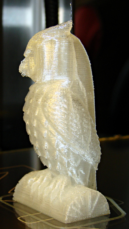
Owl – half size – left
For example, a half-scale cushwa owl printed in PLA at 165 °C with no bed cooling and these Slic3r parameters:
500 mm/s move
300 mm/s infill
200 mm/s solid infill
100 mm/s internal perimeter
50 mm/s bottom layer
30 mm/s external perimeter
1 mm retract @ 300 mm/s
The beak came out slightly droopy and each downward-pointing feather dangles a glittery drop. There’s room for improvement, but that’s pretty good a week after opening a box o’ parts…
Here’s a combined and sorted list of all the G-Code and M-Code commands for (as many of) the Free Software G-Code interpreters (that I could find) relevant to DIY 3D printing. With any luck, I now know:
What a given command does
What other interpreters do with that command
The short descriptions come from tables on the original source pages, perhaps with a bit of massaging to make things more uniform; I did as little rearranging and editing as possible.
If you see anything wrong or have another G-Code interpreter I should include, let me know…
3D Printer G-Code and M-Code Commands

27 Feb 2013
Ed Nisley - KE4ZNU

V3 - NIST RS274NGC V3- http://www.nist.gov/manuscript-publication-search.cfm?pub_id=823374
LC - LinuxCNC - http://www.linuxcnc.org/docs/
RG - ReplicatorG - http://replicat.org/gcodes and /mcodes
JF - Jetty Firmware - http://replicat.org/mcodes at bottom
RR - RepRap - http://reprap.org/wiki/G_codes (cross-linked from many G-Code pages)
MF - Marlin Firmware dialect of RR (via Dan Newman)

G0  LC  Coordinated Straight Motion Rapid
G0  MF  same as G1
G0  RG  Rapid Motion
G0  RR  Rapid move
G0  V3  rapid positioning
G1  LC  Coordinated Straight Motion Feed Rate
G1  MF  Coordinated Movement X Y Z E
G1  RG  Coordinated Motion
G1  RR  Controlled move
G1  V3  linear interpolation
G2  LC  Coordinated Helical Motion Feed Rate
G2  MF  CW ARC
G2  RG  Arc - Clockwise
G2  V3  circular/helical interpolation (clockwise)
G3  LC  Coordinated Helical Motion Feed Rate
G3  MF  CCW ARC
G3  RG  Arc - Counter Clockwise
G3  V3  circular/helical interpolation (counterclockwise)
G4  LC  Dwell
G4  MF  Dwell S<seconds> or P<milliseconds>
G4  RG  Dwell
G4  RR  Dwell
G4  V3  dwell
G5.1    LC  Quadratic B-Spline
G5.2    LC  NURBs Block Open
G5.3    LC  NURBs Block Close
G7  LC  Diameter Mode (lathe)
G8  LC  Radius Mode (lathe)
G10 LC  L10 Set Tool Table, Calculated, Workpiece
G10 LC  L11 Set Tool Table, Calculated, Fixture
G10 LC  L1  Set Tool Table Entry
G10 LC  L20 Coordinate System Origin Setting Calculated
G10 LC  L2  Coordinate System Origin Setting
G10 RG  Create Coordinate System Offset from the Absolute one
G10 RR  Head Offset
G10 V3  coordinate system origin setting
G17 LC  Arc plane XY
G17 RG  Select XY plane (default)
G17 V3  XY-plane selection
G17.1   LC  Arc plane UV
G18 LC  Arc plane ZX
G18 RG  Select XZ plane (not implemented)
G18 V3  XZ-plane selection
G18.1   LC  Arc plane WU
G19 LC  Arc plane YZ
G19 RG  Select YX plane (not implemented)
G19 V3  YZ-plane selection
G19.1   LC  Arc plane VW
G20 LC  Unit of Measure - inch
G20 RG  Inches as units
G20 RR  Set Units to Inches
G20 V3  inch system selection
G21 LC  Unit of Measure - millimeter
G21 RG  Millimeters as units
G21 RR  Set Units to Millimeters
G21 V3  millimeter system selection
G28 LC  Go to Predefined Position
G28 MF  Home all Axis
G28 RG  Home given Axes to maximum
G28 RR  Move to Origin
G28 V3  return to home
G28.1   LC  Store Predefined Position
G29-G32 RR  Bed probing
G30 LC  Go to Predefined Position
G30 RG  Go Home via Intermediate Point (not implemented)
G30 V3  return to secondary home
G30.1   LC  Store Predefined Position
G31 RG  Single probe (not implemented)
G32 RG  Probe area (not implemented)
G33 LC  Spindle Synchronized Motion
G33.1   LC  Rigid Tapping
G38.2   LC  Probe toward, stop on contact, error
G38.2   V3  straight probe
G38.3   LC  Probe toward, stop on contact
G38.4   LC  Probe away, stop on release, error
G38.5   LC  Probe away, stop on release
G40 LC  Cancel Cutter Compensation
G40 V3  cancel cutter radius compensation
G41 LC  Cutter Compensation - left
G41 V3  start cutter radius compensation left
G41.1   LC  Dynamic Cutter Compensation - left
G42 LC  Cutter Compensation - right
G42 V3  start cutter radius compensation right
G42.1   LC  Dynamic Cutter Compensation - right
G43 LC  Use Tool Length Offset from Tool Table
G43 V3  tool length offset (plus)
G43.1   LC  Dynamic Tool Length Offset
G49 LC  Cancel Tool Length Offset
G49 V3  cancel tool length offset
G53 LC  Motion in Machine Coordinate System
G53 RG  Set absolute coordinate system
G53 V3  motion in machine coordinate system
G54-G59 RG  Use coordinate system from G10 P0-5
G54 LC  Select Coordinate System 1
G54 V3  use preset work coordinate system 1
G55 LC  Select Coordinate System 2
G55 V3  use preset work coordinate system 2
G56 LC  Select Coordinate System 3
G56 V3  use preset work coordinate system 3
G57 LC  Select Coordinate System 4
G57 V3  use preset work coordinate system 4
G58 LC  Select Coordinate System 5
G58 V3  use preset work coordinate system 5
G59 LC  Select Coordinate System 6
G59 V3  use preset work coordinate system 6
G59.1   LC  Select Coordinate System 7
G59.1   V3  use preset work coordinate system 7
G59.2   LC  Select Coordinate System 8
G59.2   V3  use preset work coordinate system 8
G59.3   LC  Select Coordinate System 9
G59.3   V3  use preset work coordinate system 9
G61 LC  Path Control Mode - exact path
G61 V3  set path control mode: exact path
G61.1   LC  Path Control Mode - exact stop (same as G61)
G61.1   V3  set path control mode: exact stop
G64 LC  Path Control Mode - Optional Tolerance
G64 V3  set path control mode: continuous
G73 LC  Drilling Cycle with Chip Breaking
G76 LC  Multi-pass Threading Cycle (Lathe)
G80 LC  Cancel Motion Modes
G80 V3  cancel motion mode (including any canned cycle)
G81 LC  Drilling Cycle
G81 V3  canned cycle: drilling
G82 LC  Drilling Cycle with Dwell
G82 V3  canned cycle: drilling with dwell
G83 LC  Drilling Cycle with Peck
G83 V3  canned cycle: peck drilling
G84 V3  canned cycle: right hand tapping
G85 LC  Boring Cycle, No Dwell, Feed Out
G85 V3  canned cycle: boring, no dwell, feed out
G86 LC  Boring Cycle, Stop, Rapid Out
G86 V3  canned cycle: boring, spindle stop, rapid out
G87 V3  canned cycle: back boring
G88 V3  canned cycle: boring, spindle stop, manual out
G89 LC  Boring Cycle, Dwell, Feed Out
G89 V3  canned cycle: boring, dwell, feed out
G90 LC  G91 Distance Mode
G90 MF  Use Absolute Coordinates
G90 RG  Absolute Positioning
G90 RR  Set to Absolute Positioning
G90 V3  absolute distance mode
G90.1   LC  Arc Distance Mode - absolute IJK
G91 MF  Use Relative Coordinates
G91 RG  Relative Positioning
G91 RR  Set to Relative Positioning
G91 V3  incremental distance mode
G91.1   LC  Arc Distance Mode - incremental IJK
G92.1   V3  cancel offset coordinate systems and set parameters to zero
G92 LC  Coordinate System Offset
G92 MF  Set current position to cordinates given
G92 RG  Define current position on axes
G92 RR  Set Position
G92 V3  offset coordinate systems and set parameters
G92.1   LC  Cancel Coordinate System Offsets
G92.2   LC  Cancel Coordinate System Offsets
G92.2   V3  cancel offset coordinate systems but do not reset parameters
G92.3   LC  Restore Axis Offsets
G92.3   V3  apply parameters to offset coordinate systems
G93 LC  Feed Mode - Inverse time
G93 V3  inverse time feed rate mode
G94 LC  Feed Mode - Units per minute
G94 RG  Feed rate mode (not implemented)
G94 V3  units per minute feed rate mode
G95 LC  Feed Mode - Units per revolution
G96 LC  Constant Surface Speed
G97 LC  RPM Mode
G97 RG  Spindle speed rate
G98 LC  Canned Cycle Z Retract Mode
G98 V3  initial level return in canned cycles
G99 LC  Canned Cycle Z Retract Mode
G99 V3  R-point level return in canned cycles
G161    RG  Home negative
G162    RG  Home positive

M0  LC  Program Pause
M0  RG  Unconditional Halt (not supported on SD)
M0  RR  Stop
M0  V3  program stop
M1  LC  Program Pause - optional
M1  RG  Optional Halt (not supported on SD)
M1  RR  Sleep
M1  V3  optional program stop
M2  LC  Program End
M2  RG  End program
M2  V3  program end
M3  LC  Spindle Control - clockwise ON
M3  RG  spindle on, CW
M3  RR  Spindle On, Clockwise (CNC specific)
M3  V3  turn spindle clockwise
M4  LC  Spindle Control - counterclockwise ON
M4  RG  spindle on, CCW
M4  RR  Spindle On, Counter-Clockwise (CNC specific)
M4  V3  turn spindle counterclockwise
M5  LC  Spindle Control - OFF
M5  RG  spindle off
M5  RR  Spindle Off (CNC specific)
M5  V3  stop spindle turning
M6  LC  Tool Change
M6  RG  Tool change. This code waits until the toolhead is ready before proceeding. This is often used to wait for a toolhead to reach the its set temperature before beginning a print. ReplicatorG also supports giving a timeout with M6 P<secs>.
M6  V3  tool change
M7  LC  Coolant Control - mist ON
M7  RG  coolant A on (flood coolant)
M7  RR  Mist Coolant On (CNC specific)
M7  V3  mist coolant on
M8  LC  Coolant Control - flood ON
M8  RG  cooland B on (mist coolant)
M8  RR  Flood Coolant On (CNC specific)
M8  V3  flood coolant on
M9  LC  Coolant Control - OFF
M9  RG  all coolants off
M9  RR  Coolant Off (CNC specific)
M9  V3  mist and flood coolant off
M10 RG  close clamp
M10 RR  Vacuum On (CNC specific)
M11 RG  open clamp
M11 RR  Vacuum Off (CNC specific)
M13 RG  spindle CW and coolant A on
M14 RG  spindle CCW and coolant A on
M17 MF  Enable/Power all stepper motors
M17 RG  enable motor(s)
M17 RR  Enable/Power all stepper motors
M18 MF  Disable all stepper motors; same as M84
M18 RG  disable motor(s)
M18 RR  Disable all stepper motors
M20 MF  List SD card
M20 RR  List SD card
M21 MF  Init SD card
M21 RG  open collet
M21 RR  Initialize SD card
M22 MF  Release SD card
M22 RG  close collet
M22 RR  Release SD card
M23 MF  Select SD file (M23 filename.g)
M23 RR  Select SD file
M24 MF  Start/resume SD print
M24 RR  Start/resume SD print
M25 MF  Pause SD print
M25 RR  Pause SD print
M26 MF  Set SD position in bytes (M26 S12345)
M26 RR  Set SD position
M27 MF  Report SD print status
M27 RR  Report SD print status
M28 MF  Start SD write (M28 filename.g)
M28 RR  Begin write to SD card
M29 MF  Stop SD write
M29 RR  Stop writing to SD card
M30 LC  Program End - exchange pallet shuttles
M30 MF  Delete file from SD (M30 filename.g)
M30 RG  program rewind
M30 RR  Delete a file on the SD card
M30 V3  program end, pallet shuttle, and reset
M31 MF  Output time since last M109 or SD card start to serial
M40-M46 RG  change gear ratio (0 - 6)
M40 RR  Eject
M41 RR  Loop
M42 MF  Change pin status via gcode
M42 RR  Stop on material exhausted / Switch I/O pin
M43 RR  Stand by on material exhausted
M48 LC  Feed & Spindle Overrides - Enable
M48 V3  enable speed and feed overrides
M49 LC  Feed & Spindle Overrides - Disable
M49 V3  disable speed and feed overrides
M50 LC  Feed Override Control
M50 RG  read spindle speed
M51 LC  Spindle Override Control
M52 LC  Adaptive Feed Control
M53 LC  Feed Stop Control
M60 LC  Pallet Change Pause
M60 V3  pallet shuttle and program stop
M61 LC  Set Current Tool Number
M62 LC  Output Control - synchronized ON
M63 LC  Output Control - synchronized OFF
M64 LC  Output Control - immediate ON
M65 LC  Output Control - immediate OFF
M66 LC  Input Control - wait
M67 LC  Analog Output Control - synchronized
M68 LC  Analog Output Control - immediate
M70 RG  Display message on machine, with optional timeout specified by P-code in seconds
M71 RG  Pause activity and display message, resuming build on button push. Optional timeout specified by P-code in seconds. If timeout is specified and no button is pushed, machine should shut down or reset.
M72 RG  Play a song or tone defined by the machine, by a P-code specifying a song type. Default songs are Error Sound (P0), a Ta-da sound (P1), and a warning sound (P2). all other sounds are user or machine specific, with P2 the default for unknown sounds.
M73 RG  Manually set build percentage. Valid P values are 0 to 100, values over 100 are rounded down to 100
M80 MF  Turn on Power Supply
M80 RR  ATX Power On
M81 MF  Turn off Power Supply
M81 RR  ATX Power Off
M82 MF  Set E codes absolute (default)
M82 RR  set extruder to absolute mode
M83 MF  Set E codes relative while in Absolute Coordinates (G90) mode
M83 RR  set extruder to relative mode
M84 MF  Disable steppers until next move, or use S<seconds> to specify an inactivity timeout, after which the steppers will be disabled.  S0 to disable the timeout.
M84 RR  Stop idle hold
M85 MF  Set inactivity shutdown timer with parameter S<seconds>. To disable set zero (default)
M92 MF  Set axis_steps_per_unit - same syntax as G92
M92 RR  Set axis_steps_per_unit
M98 RR  Get axis_hysteresis_mm
M99 RR  Set axis_hysteresis_mm
M100    LC  through M199   User Defined M codes
M101    RR  Extruder on, fwd
M101    RR  Turn extruder 1 on Forward / Undo Extruder Retraction
M102    RR  Extruder on, reverse
M102    RR  Turn extruder 1 on Reverse
M103    RR  Extruder off
M103    RR  Turn all extruders off / Extruder Retraction
M104    MF  Set extruder target temp
M104    RR  Set Extruder Temperature
M104    RR  Snn set temperature in degrees Celsius
M105    MF  Read current temp
M105    RR  get extruder temperature
M105    RR  Get Extruder Temperature
M106    MF  Fan on
M106    RR  Fan On
M106    RR  turn fan on
M107    MF  Fan off
M107    RR  Fan Off
M107    RR  turn fan off
M108    RR  Set Extruder's Max Speed (Rnnn = RPM, Pnnn = PWM)
M108    RR  Set Extruder Speed
M109    MF  Wait for extruder current temp to reach target temp.
M109    RR  Set Extruder Temperature and Wait
M109    RR  Snnn set build platform temperature in degrees Celsuis
M110    RR  Set Current Line Number
M110    RR  Snnn set chamber temperature in degrees Celsius
M111    RR  Set Debug Level
M112    RR  Emergency Stop
M113    RR  Set Extruder PWM
M114    MF  Display current position
M114    MF  Output current position to serial port
M114    RR  Get Current Position
M115    MF  Capabilities string
M115    RR  Get Firmware Version and Capabilities
M116    RR  Wait
M117    MF  display message
M117    RR  Get Zero Position
M118    RR  Negotiate Features
M119    MF  Output Endstop status to serial port
M119    RR  Get Endstop Status
M120    RR  M121, M122 Snnn set the PID gain for the temperature regulator (not currently supported by ReplicatorG)
M123    RR  M124 Snnn set iMax and iMin windup guard for the PID controller (not currently supported by ReplicatorG)
M126    JF  use acceleration for subsequent instructions
M126    RG  valve open (acceleration on for subsequent instructions in the Jetty Firmware)
M126    RR  Open Valve
M127    JF  disable acceleration for subsequent instructions
M127    RG  valve close (acceleration off for subsequent instructions in the Jetty Firmware)
M127    RR  Close Valve
M128    RR  Extruder Pressure PWM
M128    RR  get position
M129    RR  Extruder pressure off
M129    RR  get range (not currently supported by ReplicatorG)
M130    RR  Set PID P value
M130    RR  set range (not currently supported by ReplicatorG)
M131    RR  Set PID I value
M132    RR  Set PID D value
M133    RR  Set PID I limit value
M134    RR  Write PID values to EEPROM
M136    RR  Print PID settings to host
M140    MF  Set bed target temp
M140    RR  Bed Temperature (Fast)
M141    RR  Chamber Temperature (Fast)
M142    RR  Holding Pressure
M143    RR  Maximum hot-end temperature
M160    RR  Number of mixed materials
M190    MF  Wait for bed current temp to reach target temp.
M190    RR  Wait for bed temperature to reach target temp
M200    JF  reset (to pick up changes)
M200    MF  Set filament diameter
M200    RR  reset driver
M200    RR  Set filament diameter / Get Endstop Status
M201    JF  set maximum rates of acceleration/deceleration
M201    MF  Set max acceleration in units/s^2 for print moves (M201 X1000 Y1000)
M201    RR  Set max printing acceleration
M202    MF  Set max acceleration in units/s^2 for travel moves (M202 X1000 Y1000) Unused in Marlin!!
M202    RR  clear buffer (not currently supported by ReplicatorG)
M202    RR  Set max travel acceleration
M203    JF  set maximum feed rates
M203    MF  Set maximum feedrate that your machine can sustain (M203 X200 Y200 Z300 E10000) in mm/sec
M203    RR  Set maximum feedrate
M204    JF  set default rates of acceleration
M204    MF  Set default acceleration: S normal moves T filament only moves (M204 S3000 T7000) im mm/sec^2  also sets minimum segment time in ms (B20000) to prevent buffer underruns and M20 minimum feedrate
M204    RR  Set default acceleration
M205    JF  set minimum feed rates and planner speed
M205    MF   advanced settings:  minimum travel speed S=while printing T=travel only,  B=minimum segment time X= maximum xy jerk, Z=maximum Z jerk, E=maximum E jerk
M205    RR  advanced settings
M206    JF  set extruded noodle diameter, extruder maximum reverse feed rate, extruder deprime, slowdown limit, and direction of extruder feed
M206    MF  set additional homeing offset
M206    RR  set home offset
M207    JF  set JKN Advance parameters K and K2
M207    RR  calibrate z axis by detecting z max length
M208    JF  set extruder steps per millimeter
M208    RR  set axis max travel
M209    JF  turn acceleration planner on or off; enable or disable override of gcode temperature settings
M209    RR  enable automatic retract
M215    JF  set steps per millimeter for each axis
M216    JF  set maximum speed changes for each axis
M220    MF  S<factor in percent> set speed factor override percentage
M220    RR  Set speed factor override percentage
M221    MF  S<factor in percent> set extrude factor override percentage
M221    RR  set extrude factor override percentage
M226    RR  Gcode Initiated Pause
M227    RR  Enable Automatic Reverse and Prime
M228    RR  Disable Automatic Reverse and Prime
M229    RR  Enable Automatic Reverse and Prime
M230    RR  Disable / Enable Wait for Temperature Change
M240    MF  Trigger a camera to take a photograph
M240    RR  Start conveyor belt motor / Echo off
M241    RR  Stop conveyor belt motor / echo on
M245    RR  Start cooler
M246    RR  Stop cooler
M300    RR  Play beep sound
M300    RR  Snnn set servo 1 position
M301    MF  Set PID parameters P I and D
M301    RR  Set PID parameters - Hot End
M301    RR  Snnn set servo 2 position
M302    MF  Allow cold extrudes
M303    MF  PID relay autotune S<temperature> sets the target temperature. (default target temperature = 150C)
M304    RR  Set PID parameters - Bed
M310    RG  (filepath) logging
M311    RG  stop logging
M312    RG  (message) log message
M320    RG  acceleration on for subsequent instructions
M321    RG  acceleration off for subsequent instructions
M400    MF  Finish all moves
M420    RR  Set RGB Colors as PWM
M500    MF  stores paramters in EEPROM
M500    RR  stores paramters in EEPROM
M501    MF  reads parameters from EEPROM (if you need reset them after you changed them temporarily).
M501    RR  reads parameters from EEPROM
M502    MF  reverts to the default "factory settings".  You still need to store them in EEPROM afterwards if you want to.
M502    RR  reverts to the default "factory settings".
M503    MF  print the current settings (from memory not from eeprom)
M503    RR  Print settings
M999    MF  Restart after being stopped by error
Bus 005 Device 001: ID 1d6b:0001 Linux Foundation 1.1 root hub
Bus 004 Device 006: ID 06f2:0011 Emine Technology Co. KVM Switch Keyboard
Bus 004 Device 005: ID 046d:c401 Logitech, Inc. TrackMan Marble Wheel
Bus 004 Device 004: ID 04d9:1203 Holtek Semiconductor, Inc. MC Industries Keyboard
Bus 004 Device 003: ID 046d:c216 Logitech, Inc. Dual Action Gamepad
Bus 004 Device 002: ID 0451:2046 Texas Instruments, Inc. TUSB2046 Hub
Bus 004 Device 001: ID 1d6b:0001 Linux Foundation 1.1 root hub
Bus 003 Device 001: ID 1d6b:0001 Linux Foundation 1.1 root hub
Bus 002 Device 002: ID 2341:8036
Bus 002 Device 001: ID 1d6b:0001 Linux Foundation 1.1 root hub
Bus 001 Device 001: ID 1d6b:0002 Linux Foundation 2.0 root hub
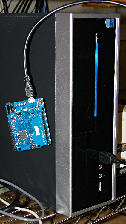
For whatever reason, this board doesn’t report a device name. It’s plugged into the same USB port as that mouse, so it gets the same Bus and Device numbers, which helps confirm that’s the board.
Querying the attributes with udevadm produces the all-important product string:
halrun
halcmd: loadusr -W hal_input -KRAL Leo
halcmd: show all
Loaded HAL Components:
ID      Type  Name                                      PID   State
     5  User  hal_input                                 11265 ready
     3  User  halcmd11264                               11264 ready

Component Pins:
Owner   Type  Dir         Value  Name
     5  bit   OUT         FALSE  input.0.btn-middle
     5  bit   OUT          TRUE  input.0.btn-middle-not
     5  bit   OUT         FALSE  input.0.btn-mouse
     5  bit   OUT          TRUE  input.0.btn-mouse-not
     5  bit   OUT         FALSE  input.0.btn-right
     5  bit   OUT          TRUE  input.0.btn-right-not
     5  bit   OUT         FALSE  input.0.key-0
     5  bit   OUT          TRUE  input.0.key-0-not
     5  bit   OUT         FALSE  input.0.key-1
     5  bit   OUT          TRUE  input.0.key-1-not
     5  bit   OUT         FALSE  input.0.key-102nd
     5  bit   OUT          TRUE  input.0.key-102nd-not
     5  bit   OUT         FALSE  input.0.key-2
     5  bit   OUT          TRUE  input.0.key-2-not
     5  bit   OUT         FALSE  input.0.key-3
     5  bit   OUT          TRUE  input.0.key-3-not
     5  bit   OUT         FALSE  input.0.key-4
     5  bit   OUT          TRUE  input.0.key-4-not
     5  bit   OUT         FALSE  input.0.key-5
     5  bit   OUT          TRUE  input.0.key-5-not
     5  bit   OUT         FALSE  input.0.key-6
     5  bit   OUT          TRUE  input.0.key-6-not
     5  bit   OUT         FALSE  input.0.key-7
     5  bit   OUT          TRUE  input.0.key-7-not
     5  bit   OUT         FALSE  input.0.key-8
     5  bit   OUT          TRUE  input.0.key-8-not
     5  bit   OUT         FALSE  input.0.key-9
     5  bit   OUT          TRUE  input.0.key-9-not
     5  bit   OUT         FALSE  input.0.key-a
     5  bit   OUT          TRUE  input.0.key-a-not
     5  bit   OUT         FALSE  input.0.key-apostrophe
     5  bit   OUT          TRUE  input.0.key-apostrophe-not
     5  bit   OUT         FALSE  input.0.key-b
     5  bit   OUT          TRUE  input.0.key-b-not
     5  bit   OUT         FALSE  input.0.key-backslash
     5  bit   OUT          TRUE  input.0.key-backslash-not
     5  bit   OUT         FALSE  input.0.key-backspace
     5  bit   OUT          TRUE  input.0.key-backspace-not
     5  bit   OUT         FALSE  input.0.key-c
     5  bit   OUT          TRUE  input.0.key-c-not
     5  bit   OUT         FALSE  input.0.key-capslock
     5  bit   OUT          TRUE  input.0.key-capslock-not
     5  bit   OUT         FALSE  input.0.key-comma
     5  bit   OUT          TRUE  input.0.key-comma-not
     5  bit   OUT         FALSE  input.0.key-compose
     5  bit   OUT          TRUE  input.0.key-compose-not
     5  bit   OUT         FALSE  input.0.key-d
     5  bit   OUT          TRUE  input.0.key-d-not
     5  bit   OUT         FALSE  input.0.key-delete
     5  bit   OUT          TRUE  input.0.key-delete-not
     5  bit   OUT         FALSE  input.0.key-dot
     5  bit   OUT          TRUE  input.0.key-dot-not
     5  bit   OUT         FALSE  input.0.key-down
     5  bit   OUT          TRUE  input.0.key-down-not
     5  bit   OUT         FALSE  input.0.key-e
     5  bit   OUT          TRUE  input.0.key-e-not
     5  bit   OUT         FALSE  input.0.key-end
     5  bit   OUT          TRUE  input.0.key-end-not
     5  bit   OUT         FALSE  input.0.key-enter
     5  bit   OUT          TRUE  input.0.key-enter-not
     5  bit   OUT         FALSE  input.0.key-equal
     5  bit   OUT          TRUE  input.0.key-equal-not
     5  bit   OUT         FALSE  input.0.key-esc
     5  bit   OUT          TRUE  input.0.key-esc-not
     5  bit   OUT         FALSE  input.0.key-f
     5  bit   OUT          TRUE  input.0.key-f-not
     5  bit   OUT         FALSE  input.0.key-f1
     5  bit   OUT          TRUE  input.0.key-f1-not
     5  bit   OUT         FALSE  input.0.key-f10
     5  bit   OUT          TRUE  input.0.key-f10-not
     5  bit   OUT         FALSE  input.0.key-f11
     5  bit   OUT          TRUE  input.0.key-f11-not
     5  bit   OUT         FALSE  input.0.key-f12
     5  bit   OUT          TRUE  input.0.key-f12-not
     5  bit   OUT         FALSE  input.0.key-f2
     5  bit   OUT          TRUE  input.0.key-f2-not
     5  bit   OUT         FALSE  input.0.key-f3
     5  bit   OUT          TRUE  input.0.key-f3-not
     5  bit   OUT         FALSE  input.0.key-f4
     5  bit   OUT          TRUE  input.0.key-f4-not
     5  bit   OUT         FALSE  input.0.key-f5
     5  bit   OUT          TRUE  input.0.key-f5-not
     5  bit   OUT         FALSE  input.0.key-f6
     5  bit   OUT          TRUE  input.0.key-f6-not
     5  bit   OUT         FALSE  input.0.key-f7
     5  bit   OUT          TRUE  input.0.key-f7-not
     5  bit   OUT         FALSE  input.0.key-f8
     5  bit   OUT          TRUE  input.0.key-f8-not
     5  bit   OUT         FALSE  input.0.key-f9
     5  bit   OUT          TRUE  input.0.key-f9-not
     5  bit   OUT         FALSE  input.0.key-g
     5  bit   OUT          TRUE  input.0.key-g-not
     5  bit   OUT         FALSE  input.0.key-grave
     5  bit   OUT          TRUE  input.0.key-grave-not
     5  bit   OUT         FALSE  input.0.key-h
     5  bit   OUT          TRUE  input.0.key-h-not
     5  bit   OUT         FALSE  input.0.key-home
     5  bit   OUT          TRUE  input.0.key-home-not
     5  bit   OUT         FALSE  input.0.key-i
     5  bit   OUT          TRUE  input.0.key-i-not
     5  bit   OUT         FALSE  input.0.key-insert
     5  bit   OUT          TRUE  input.0.key-insert-not
     5  bit   OUT         FALSE  input.0.key-j
     5  bit   OUT          TRUE  input.0.key-j-not
     5  bit   OUT         FALSE  input.0.key-k
     5  bit   OUT          TRUE  input.0.key-k-not
     5  bit   OUT         FALSE  input.0.key-kp0
     5  bit   OUT          TRUE  input.0.key-kp0-not
     5  bit   OUT         FALSE  input.0.key-kp1
     5  bit   OUT          TRUE  input.0.key-kp1-not
     5  bit   OUT         FALSE  input.0.key-kp2
     5  bit   OUT          TRUE  input.0.key-kp2-not
     5  bit   OUT         FALSE  input.0.key-kp3
     5  bit   OUT          TRUE  input.0.key-kp3-not
     5  bit   OUT         FALSE  input.0.key-kp4
     5  bit   OUT          TRUE  input.0.key-kp4-not
     5  bit   OUT         FALSE  input.0.key-kp5
     5  bit   OUT          TRUE  input.0.key-kp5-not
     5  bit   OUT         FALSE  input.0.key-kp6
     5  bit   OUT          TRUE  input.0.key-kp6-not
     5  bit   OUT         FALSE  input.0.key-kp7
     5  bit   OUT          TRUE  input.0.key-kp7-not
     5  bit   OUT         FALSE  input.0.key-kp8
     5  bit   OUT          TRUE  input.0.key-kp8-not
     5  bit   OUT         FALSE  input.0.key-kp9
     5  bit   OUT          TRUE  input.0.key-kp9-not
     5  bit   OUT         FALSE  input.0.key-kpasterisk
     5  bit   OUT          TRUE  input.0.key-kpasterisk-not
     5  bit   OUT         FALSE  input.0.key-kpdot
     5  bit   OUT          TRUE  input.0.key-kpdot-not
     5  bit   OUT         FALSE  input.0.key-kpenter
     5  bit   OUT          TRUE  input.0.key-kpenter-not
     5  bit   OUT         FALSE  input.0.key-kpminus
     5  bit   OUT          TRUE  input.0.key-kpminus-not
     5  bit   OUT         FALSE  input.0.key-kpplus
     5  bit   OUT          TRUE  input.0.key-kpplus-not
     5  bit   OUT         FALSE  input.0.key-kpslash
     5  bit   OUT          TRUE  input.0.key-kpslash-not
     5  bit   OUT         FALSE  input.0.key-l
     5  bit   OUT          TRUE  input.0.key-l-not
     5  bit   OUT         FALSE  input.0.key-left
     5  bit   OUT          TRUE  input.0.key-left-not
     5  bit   OUT         FALSE  input.0.key-leftalt
     5  bit   OUT          TRUE  input.0.key-leftalt-not
     5  bit   OUT         FALSE  input.0.key-leftbrace
     5  bit   OUT          TRUE  input.0.key-leftbrace-not
     5  bit   OUT         FALSE  input.0.key-leftctrl
     5  bit   OUT          TRUE  input.0.key-leftctrl-not
     5  bit   OUT         FALSE  input.0.key-leftmeta
     5  bit   OUT          TRUE  input.0.key-leftmeta-not
     5  bit   OUT         FALSE  input.0.key-leftshift
     5  bit   OUT          TRUE  input.0.key-leftshift-not
     5  bit   OUT         FALSE  input.0.key-m
     5  bit   OUT          TRUE  input.0.key-m-not
     5  bit   OUT         FALSE  input.0.key-minus
     5  bit   OUT          TRUE  input.0.key-minus-not
     5  bit   OUT         FALSE  input.0.key-n
     5  bit   OUT          TRUE  input.0.key-n-not
     5  bit   OUT         FALSE  input.0.key-numlock
     5  bit   OUT          TRUE  input.0.key-numlock-not
     5  bit   OUT         FALSE  input.0.key-o
     5  bit   OUT          TRUE  input.0.key-o-not
     5  bit   OUT         FALSE  input.0.key-p
     5  bit   OUT          TRUE  input.0.key-p-not
     5  bit   OUT         FALSE  input.0.key-pagedown
     5  bit   OUT          TRUE  input.0.key-pagedown-not
     5  bit   OUT         FALSE  input.0.key-pageup
     5  bit   OUT          TRUE  input.0.key-pageup-not
     5  bit   OUT         FALSE  input.0.key-pause
     5  bit   OUT          TRUE  input.0.key-pause-not
     5  bit   OUT         FALSE  input.0.key-q
     5  bit   OUT          TRUE  input.0.key-q-not
     5  bit   OUT         FALSE  input.0.key-r
     5  bit   OUT          TRUE  input.0.key-r-not
     5  bit   OUT         FALSE  input.0.key-right
     5  bit   OUT          TRUE  input.0.key-right-not
     5  bit   OUT         FALSE  input.0.key-rightalt
     5  bit   OUT          TRUE  input.0.key-rightalt-not
     5  bit   OUT         FALSE  input.0.key-rightbrace
     5  bit   OUT          TRUE  input.0.key-rightbrace-not
     5  bit   OUT         FALSE  input.0.key-rightctrl
     5  bit   OUT          TRUE  input.0.key-rightctrl-not
     5  bit   OUT         FALSE  input.0.key-rightmeta
     5  bit   OUT          TRUE  input.0.key-rightmeta-not
     5  bit   OUT         FALSE  input.0.key-rightshift
     5  bit   OUT          TRUE  input.0.key-rightshift-not
     5  bit   OUT         FALSE  input.0.key-s
     5  bit   OUT          TRUE  input.0.key-s-not
     5  bit   OUT         FALSE  input.0.key-scrolllock
     5  bit   OUT          TRUE  input.0.key-scrolllock-not
     5  bit   OUT         FALSE  input.0.key-semicolon
     5  bit   OUT          TRUE  input.0.key-semicolon-not
     5  bit   OUT         FALSE  input.0.key-slash
     5  bit   OUT          TRUE  input.0.key-slash-not
     5  bit   OUT         FALSE  input.0.key-space
     5  bit   OUT          TRUE  input.0.key-space-not
     5  bit   OUT         FALSE  input.0.key-sysrq
     5  bit   OUT          TRUE  input.0.key-sysrq-not
     5  bit   OUT         FALSE  input.0.key-t
     5  bit   OUT          TRUE  input.0.key-t-not
     5  bit   OUT         FALSE  input.0.key-tab
     5  bit   OUT          TRUE  input.0.key-tab-not
     5  bit   OUT         FALSE  input.0.key-u
     5  bit   OUT          TRUE  input.0.key-u-not
     5  bit   OUT         FALSE  input.0.key-up
     5  bit   OUT          TRUE  input.0.key-up-not
     5  bit   OUT         FALSE  input.0.key-v
     5  bit   OUT          TRUE  input.0.key-v-not
     5  bit   OUT         FALSE  input.0.key-w
     5  bit   OUT          TRUE  input.0.key-w-not
     5  bit   OUT         FALSE  input.0.key-x
     5  bit   OUT          TRUE  input.0.key-x-not
     5  bit   OUT         FALSE  input.0.key-y
     5  bit   OUT          TRUE  input.0.key-y-not
     5  bit   OUT         FALSE  input.0.key-z
     5  bit   OUT          TRUE  input.0.key-z-not
     5  s32   OUT             0  input.0.rel-wheel-counts
     5  float OUT             0  input.0.rel-wheel-position
     5  bit   IN          FALSE  input.0.rel-wheel-reset
     5  float IN              1  input.0.rel-wheel-scale
     5  s32   OUT             0  input.0.rel-x-counts
     5  float OUT             0  input.0.rel-x-position
     5  bit   IN          FALSE  input.0.rel-x-reset
     5  float IN              1  input.0.rel-x-scale
     5  s32   OUT             0  input.0.rel-y-counts
     5  float OUT             0  input.0.rel-y-position
     5  bit   IN          FALSE  input.0.rel-y-reset
     5  float IN              1  input.0.rel-y-scale
That’s a pretty decent assortment of directly usable names and features, even without keyboard LEDs. The mouse pins could be repurposed for general sensor values:
position = float = count / scale (why divided? I don’t know)
scale = float = turns counts into position
reset = bit = resets position or maybe count (not sure)
I think you could use count to transfer a bare ADC reading from the Leonardo, then use scale to get the actual voltage in “position”. In that situation, reset wouldn’t be at all useful.
The keyboard pins could transfer Boolean sensors.
You’d want to give HAL exclusive control of the Leonardo-is-not-a-mouse, because the incoming data would make hash of the, ah, LinuxCNC UI experience in short order. I’m not sure how to control that; the Leonardo advice boils down to “be careful” and “use a physical switch”.
I have *no* idea where the names come from, but apparently the OS / kernel / something has a HID layer that translates bare USB capability bits into strings. How that relates to a particular device, what the choices might be, how one could add / replace the names for a given device, and all that, I don’t know yet.
Prompted by that comment, a bit more data emerges.
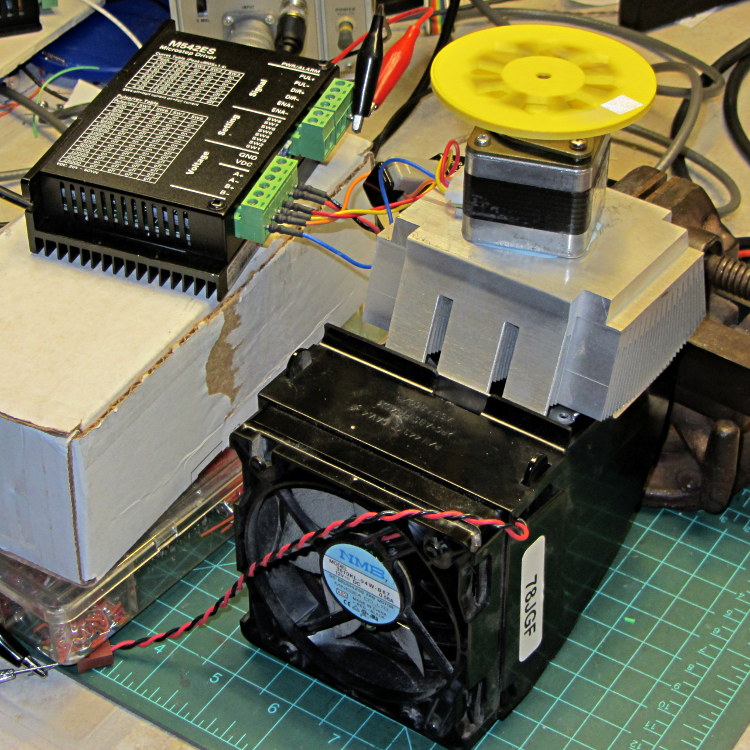
This unsteady ziggurat barely supports the aluminum CPU heatsink atop a PC CPU exhaust duct; the two came from different PCs and have no relation to each other. The vise in the background keeps the whole affair from falling over. The fan sucks air through the heatsink and exhausts it out the front.
NEMA 17 Stepper – Heatsink with Fan
Throughout all this, the stepper driver runs at a bit over 10 k step/sec, tuned to avoid the howling mechanical resonances in that stack. At 1/8 microstepping, that’s 6.25 rev/s = 375 RPM, which would drive the Thing-O-Matic at 210 mm/s and the M2 at 225 mm/s. Your speed will vary, of course, depending on the pulley diameter / number of teeth / belt pitch, etc.
Under the same conditions as before (i.e., no thermal compound, fan off), the stepper stabilized at 143 °F = 62 °C in the 57 °F = 14 °C Basement Laboratory ambient, with 1.91 A peak current (I don’t believe that second decimal place, either) and a 6.6 °C/W case-to-ambient coefficient. That’s close enough to the 63 °C and 6.7 °C/W coefficient from the earlier test, so the conditions seem roughly the same.
Smoothing a thin layer of heatsink compound on the butt of the motor, then squishing it firmly atop the heatsink, cut the temperature to 130 °F = 53 °C without the fan. That suggests the case-to-ambient coefficient is now 5.3 °C/W: the thermal compound helps by 1.3 °C/W.
Turning on the fan drops the case temperature to 84 °F = 29 °C, which works out to a coefficient of 2.1 °C/W. Obviously, moving air over that heatsink helps the cooling a lot: the heatsink felt cold to the touch and the motor case was barely warm.
Increasing the current to 2.37 A dissipates 11.2 W, which would be scary without the heatsink and air flow. The temperature stabilized at 91 °F = 33 °C, for a coefficient of 1.7 °C/W.
At 2.83 A = 16 W, the temperature rises to 100 °F = 38 °C, with a coefficient of 1.5 °C/W. While it’s not unstoppable with that much current, the motor has plenty of torque! The motor becomes pleasantly warm, the heatsink stays just above cool, and all seems right with the world. I suspect the windings get a bit toasty in there, but they can’t possibly be worse off than inside a case at boiling-water temperatures.
Using the original insulated-motor coefficient of 19 °C/W, 16 W would cook the motor at 320 °C. Perhaps the case would make a nice extruder heater after it stopped being a motor?
[Update: See the comments for the results of just blowing air over the motor case.]
You’ve probably seen this exchange on whatever DIY 3D printing forum you monitor:
My stepper motors get scorching hot, what should I do?
Turn down the current!
That worked great, but …
… now all my objects have a shift in the middle.
Your motor is losing steps: turn up the current!
Uh, right.
NEMA 17 Stepper on cloth
So, with that setup on the bench, I ran a simple experiment with current, temperature, and heat transfer. Most DIY 3D printers have stepper motors attached to a plywood chassis or plastic holder, so the first data point comes from a motor with no mechanical thermal path to the outside world (which is the Basement Laboratory at 14 °C ambient).
Running at about 1200 step/s with a winding current of 1 A peak from a 24 A supply, the motor stabilized at 52 °C = 125 °F after half an hour.
Both windings have a 2 Ω resistance and carry 1 A peak = 0.7 A rms, so the total power dissipation is:
2 × [(1 A / √2)2 × 2 Ω] = 2 W
That’s the same power produced with the motor stopped at a full step position, where the peak current flows in a single winding and the other winding carries zero current:
(1 A)2 × 2 Ω = 2 W
The temperature rise suggests a thermal coefficient of about 19 °C/W = (52 °C – 14 °C) / 2 W.
The next current setting on the driver is 1.46 A, which doubles the power dissipation to 4.3 W. Assuming a large number of linearities, that would cook the motor at 82 °C = 180 °F above ambient. Even though the motor could probably withstand that temperature, for what should be obvious reasons I didn’t go there.
Instead, I parked the motor atop a big CPU heatsink harvested from an obsolete PC, sans thermal compound, mechanical fitting, and anything more secure than gravity holding it in place:
NEMA 17 Stepper on Heatsink
The results:
Ambient
14
°C
Winding
2
ohm
A pk
A rms
Power W
Case °C
°C/W amb
°C/W incr
1.00
0.71
2.0
28
7.0
7.0
1.46
1.03
4.3
42
6.6
6.2
1.91
1.35
7.3
63
6.7
6.9
The thermal coefficients represent the combination of all interfaces from motor case to ambient, but the case and heatsink stabilized to about the same temperature, so the main limit (as always) will be heat transfer to ambient air. Obviously, the heatsink sits in the wrong orientation with little-to-no air flow, not to mention that the butt end of a stepper motor isn’t precisely machined and has plenty of air between the two surfaces. Improving all that would be in the nature of fine tuning and should substantially lower the coefficient.
What’s of interest: just perching the motor on a big chunk of aluminum dropped the case temperature 24 °C without no further effort.
Blowing air over the case (probably) won’t be nearly as effective. Epoxy-ing a liquid-cooled cold plate to the end cap would improve the situation beyond all reasonable bounds, plus confer extreme geek cred.
Hmmm, the Warehouse Wing does have some copper tubing…
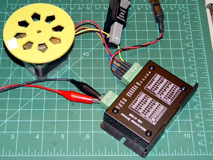
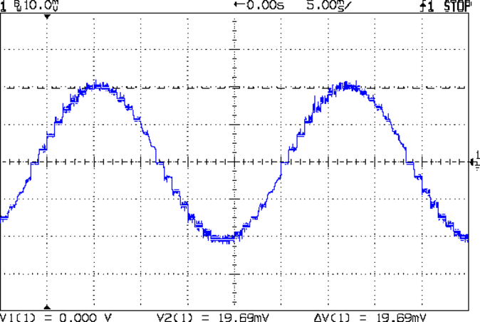
As you saw earlier the low-speed waveform looked reasonably good, although the HB-415M driver produces only 71% of its rated current (so it’s actually 1 A peak, not the 1.5 A in the caption):
HB-415M 8-step 1.5A 20V
The driver runs in 1/8 microstep mode, which means 1 revolution = 8 × 200 step = 1600 steps. Each cycle of that stepped sine wave has 32 microsteps = 4 full steps/cycle × 8 microsteps. One cycle is about 27 ms, so 1 step = 840 µs → 1200 step/s → 0.74 rev/s → 44 rpm. The Thing-O-Matic runs at 47 step/mm → 34 mm/rev, so this speed corresponds to travel at 25 mm/s, roughly the usual printing pace.
Admittedly, that hairball on the bench isn’t a realistic arrangement, because the motor runs with no load. On the other paw, assuming you’ve done a good job eliminating mechanical binding, then it’s probably pretty close to what you’d see during constant-speed travel.
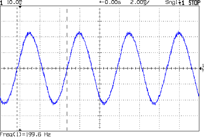
Cranking the pulse generator to 6400 step/s = 133 mm/s produces this waveform:
HB-415M 1A 8step 24V
The power supply was 24 V, but there was no visible difference at 20 V. The driver evidently can’t control the winding current on the downward side of the waveform. Adding some frictional torque by grabbing the yellow interrupter wheel improved the situation, but not by much.
A box of 2M542 drivers just arrived from a nominally reputable supplier, although they were actually labeled M542ES. Under the same conditions, they produce this waveform:
M542ES 1A 8step 24V
So there’s something to be said for larger drivers; the HB-415M drivers were operating at their upper limit and the M542ES at their lower limit, both producing close to 1 A peak.
I’ve always wondered what the LinuxCNC HAL pin names would be for an ordinary mouse, particularly nowadays when an Arduino Leonardo can become a USB HID gadget without much effort at all. If one had a Leonardo and l337 programming skillz, one might receive far more interesting data than just fast-twitch muscle movement…
Bus 005 Device 001: ID 1d6b:0001 Linux Foundation 1.1 root hub
Bus 004 Device 006: ID 06f2:0011 Emine Technology Co. KVM Switch Keyboard
Bus 004 Device 005: ID 046d:c401 Logitech, Inc. TrackMan Marble Wheel
Bus 004 Device 004: ID 04d9:1203 Holtek Semiconductor, Inc. MC Industries Keyboard
Bus 004 Device 003: ID 046d:c216 Logitech, Inc. Dual Action Gamepad
Bus 004 Device 002: ID 0451:2046 Texas Instruments, Inc. TUSB2046 Hub
Bus 004 Device 001: ID 1d6b:0001 Linux Foundation 1.1 root hub
Bus 003 Device 001: ID 1d6b:0001 Linux Foundation 1.1 root hub
Bus 002 Device 002: ID 046d:c077 Logitech, Inc.
Bus 002 Device 001: ID 1d6b:0001 Linux Foundation 1.1 root hub
Bus 001 Device 001: ID 1d6b:0002 Linux Foundation 2.0 root hub
Fire up halrun, load hal_input, and dump the pins:
halrun
halcmd: loadusr -W hal_input -KRAL Optical
halcmd: show all
Loaded HAL Components:
ID      Type  Name                                      PID   State
     5  User  hal_input                                  1693 ready
     3  User  halcmd1692                                 1692 ready

Component Pins:
Owner   Type  Dir         Value  Name
     5  bit   OUT         FALSE  input.0.btn-back
     5  bit   OUT          TRUE  input.0.btn-back-not
     5  bit   OUT         FALSE  input.0.btn-extra
     5  bit   OUT          TRUE  input.0.btn-extra-not
     5  bit   OUT         FALSE  input.0.btn-forward
     5  bit   OUT          TRUE  input.0.btn-forward-not
     5  bit   OUT         FALSE  input.0.btn-middle
     5  bit   OUT          TRUE  input.0.btn-middle-not
     5  bit   OUT         FALSE  input.0.btn-mouse
     5  bit   OUT          TRUE  input.0.btn-mouse-not
     5  bit   OUT         FALSE  input.0.btn-right
     5  bit   OUT          TRUE  input.0.btn-right-not
     5  bit   OUT         FALSE  input.0.btn-side
     5  bit   OUT          TRUE  input.0.btn-side-not
     5  bit   OUT         FALSE  input.0.btn-task
     5  bit   OUT          TRUE  input.0.btn-task-not
     5  s32   OUT             0  input.0.rel-hwheel-counts
     5  float OUT             0  input.0.rel-hwheel-position
     5  bit   IN          FALSE  input.0.rel-hwheel-reset
     5  float IN              1  input.0.rel-hwheel-scale
     5  s32   OUT             0  input.0.rel-wheel-counts
     5  float OUT             0  input.0.rel-wheel-position
     5  bit   IN          FALSE  input.0.rel-wheel-reset
     5  float IN              1  input.0.rel-wheel-scale
     5  s32   OUT             0  input.0.rel-x-counts
     5  float OUT             0  input.0.rel-x-position
     5  bit   IN          FALSE  input.0.rel-x-reset
     5  float IN              1  input.0.rel-x-scale
     5  s32   OUT             0  input.0.rel-y-counts
     5  float OUT             0  input.0.rel-y-position
     5  bit   IN          FALSE  input.0.rel-y-reset
     5  float IN              1  input.0.rel-y-scale
... snippage ...