The Smell of Molten Projects in the Morning

Ed Nisley's Blog: Shop notes, electronics, firmware, machinery, 3D printing, laser cuttery, and curiosities. Contents: 100% human thinking, 0% AI slop.

Tag: M2

Using and tweaking a Makergear M2 3D printer

  • Kenmore 158: Hall Effect Pedal Connector

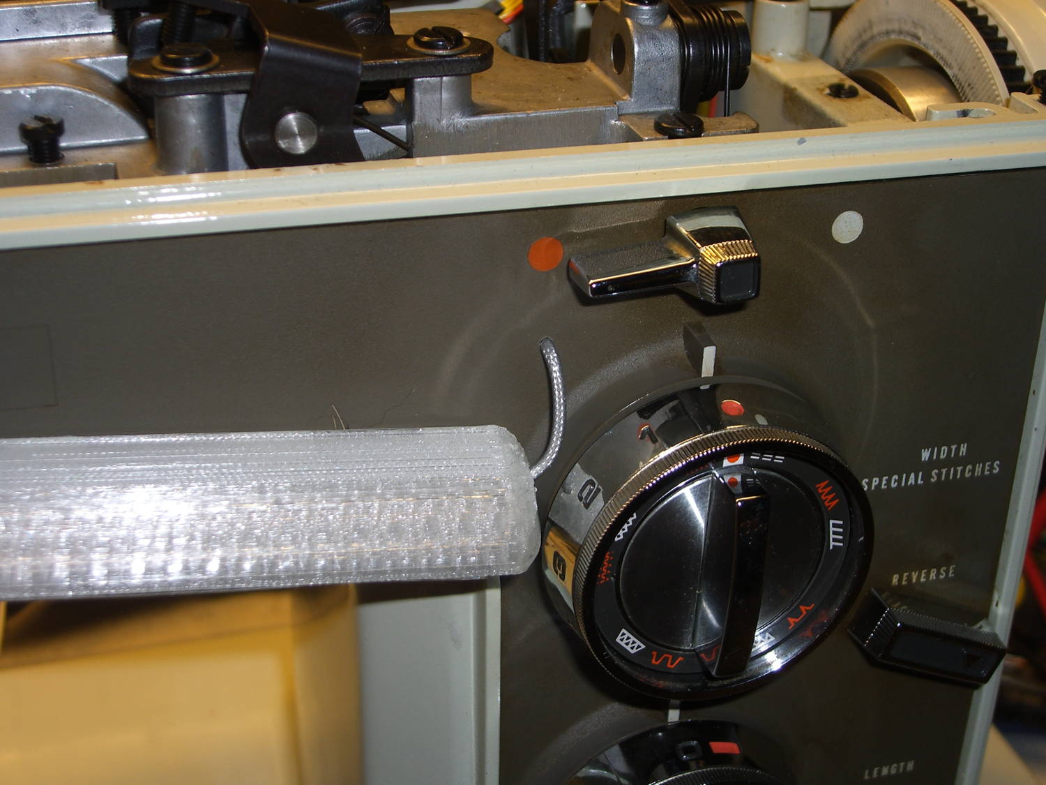
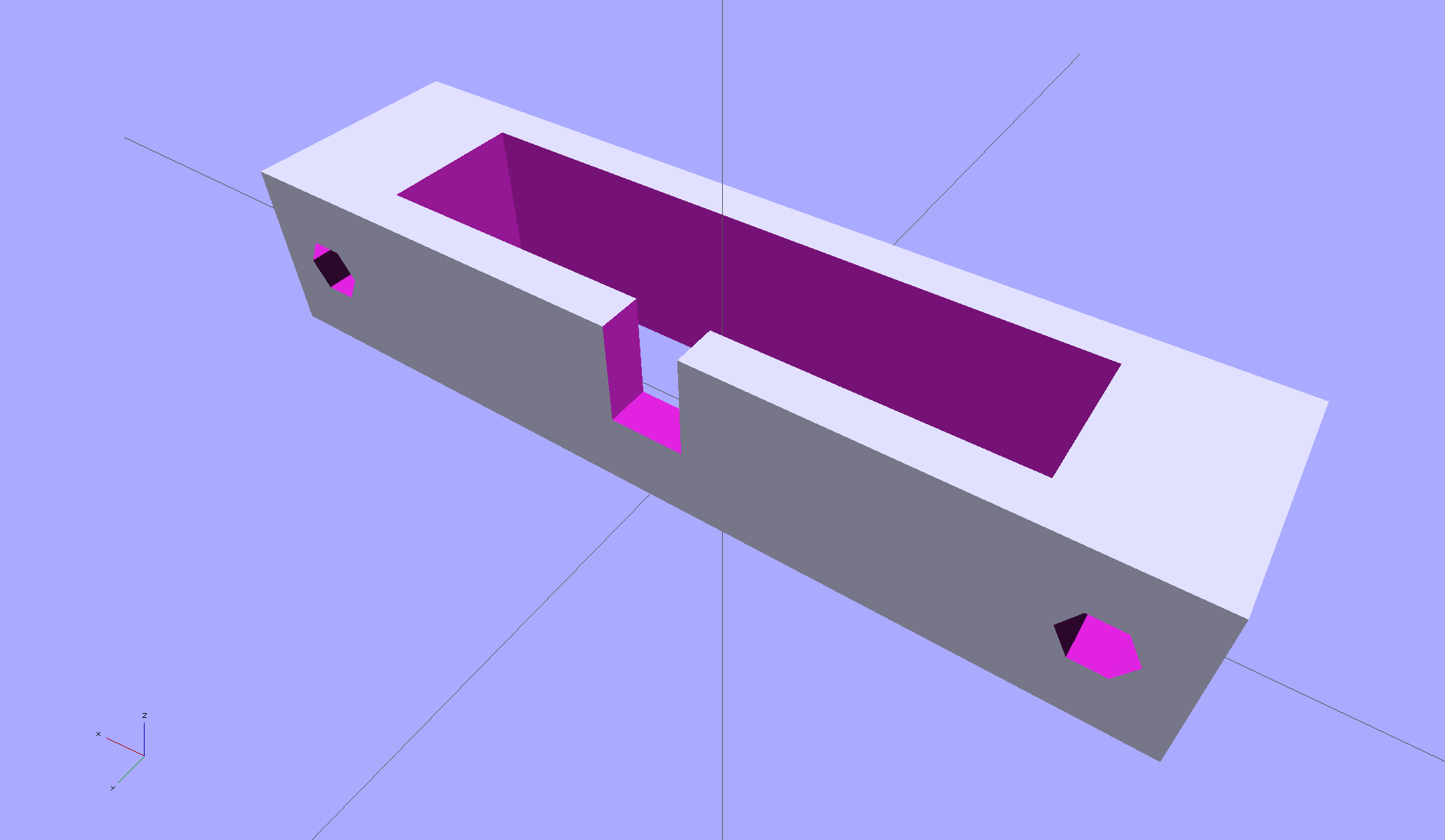
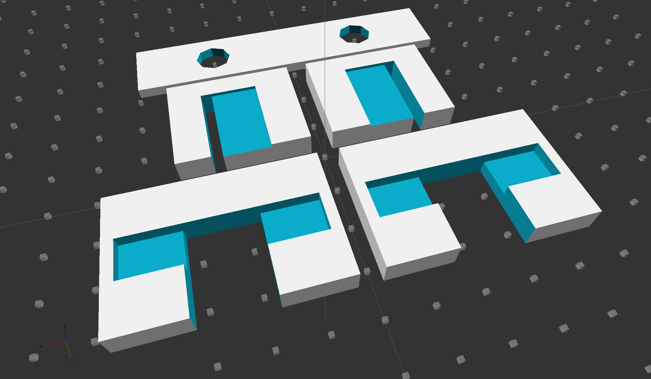
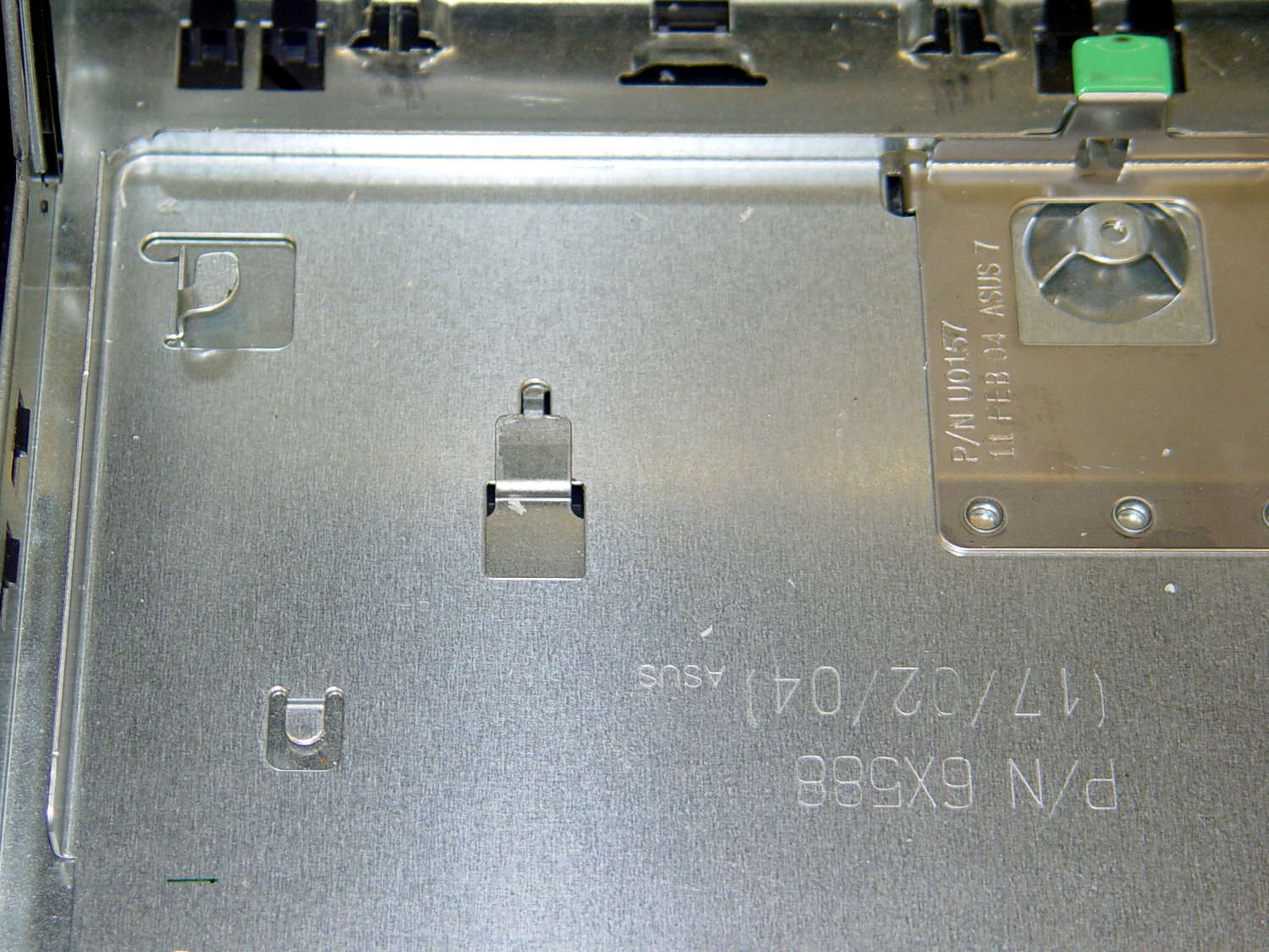
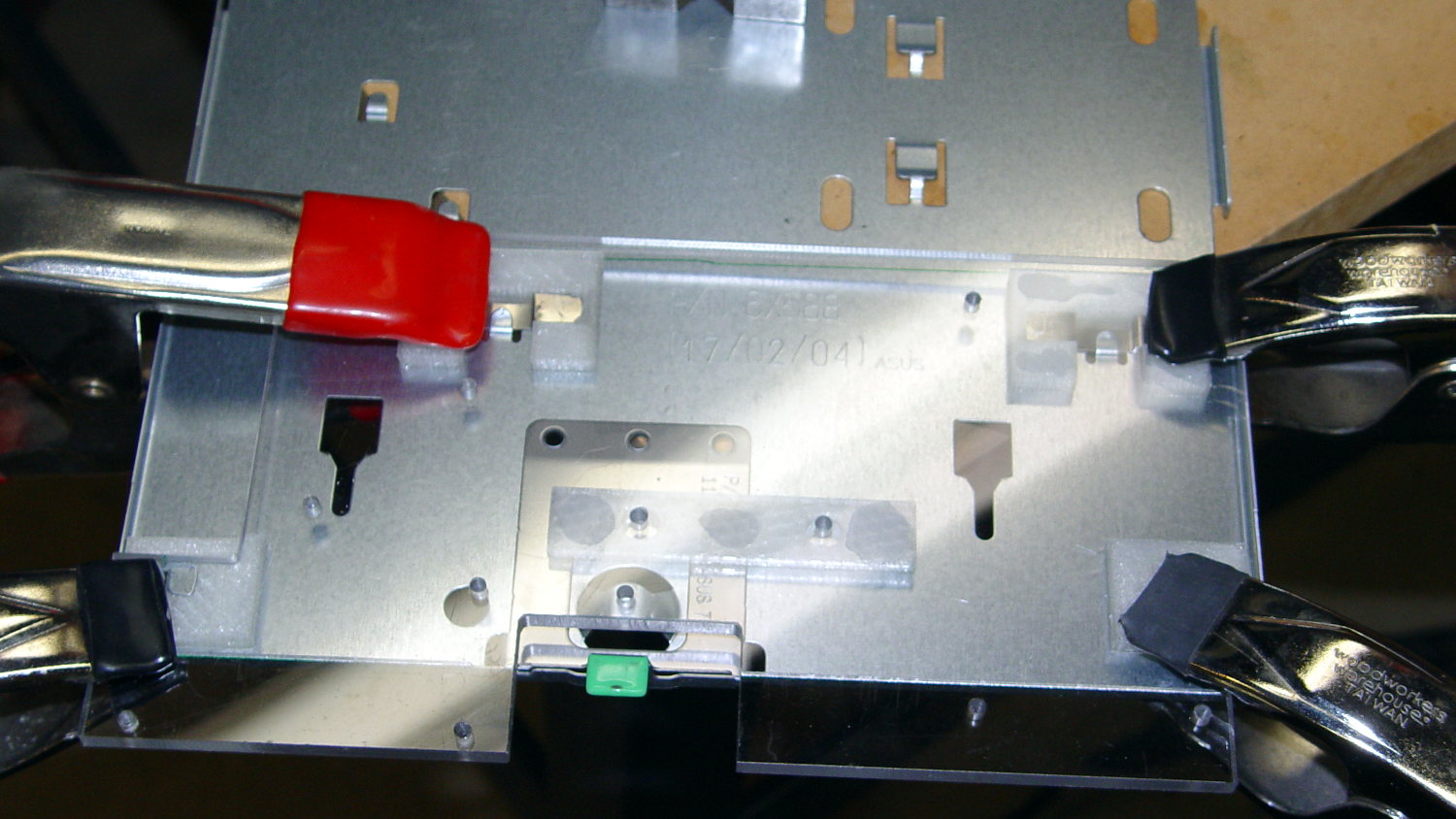
    Built back in 2004, the Dell GX270 PC had PS/2 keyboard and mouse ports on its back panel, so I put a PS/2 plug on the cable from the Hall effect sensor in the foot pedal. Although the original sockets mounted on a complex system board structure that I can’t repurpose, it’s easy enough to conjure up a mount for a single socket on the back panel:

    PS2 Socket Mount
    PS2 Socket Mount

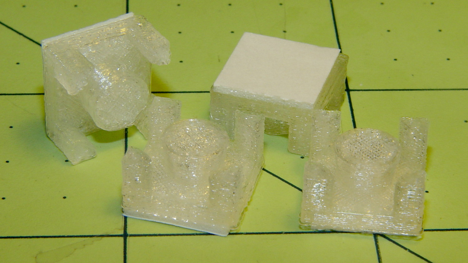
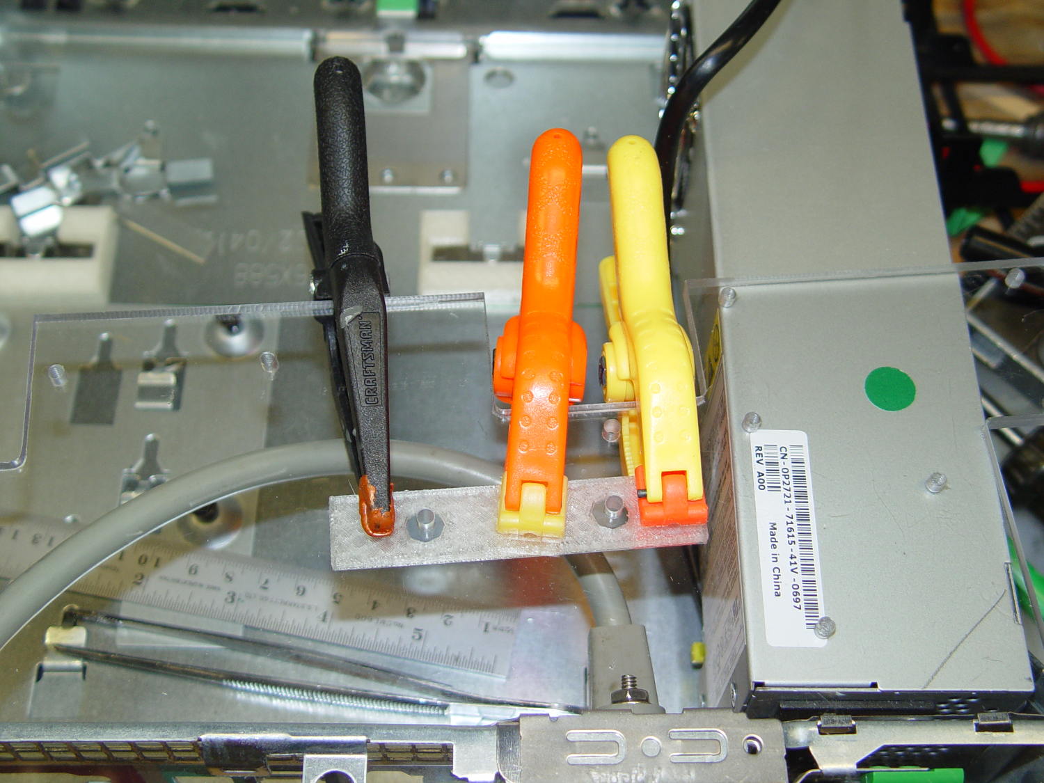
    A quick fit check verified the dimensions:

    PS2 Connector mount - trial fit on platform
    PS2 Connector mount – trial fit on platform

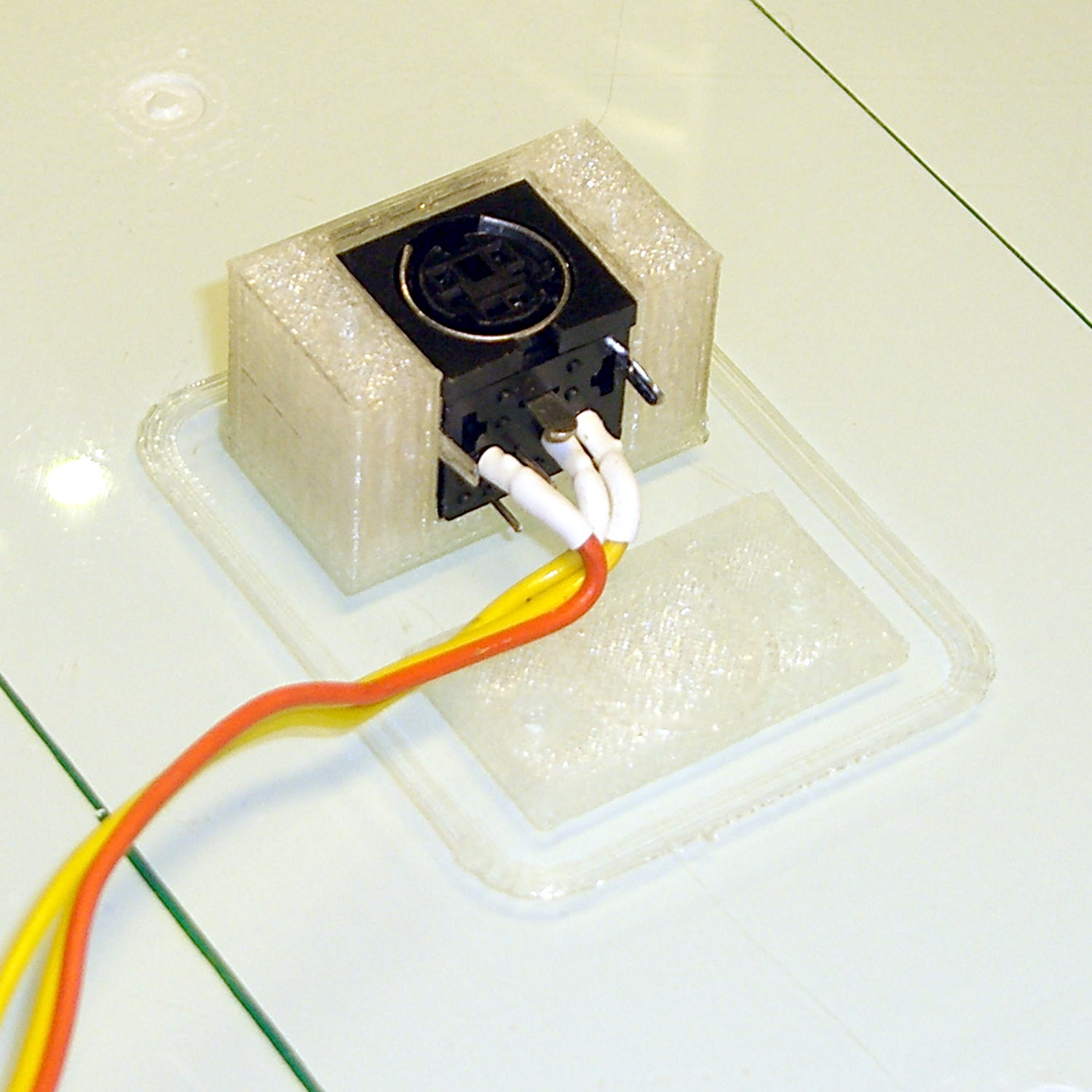
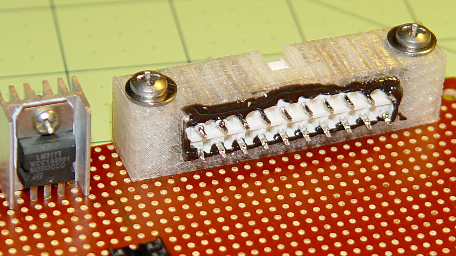
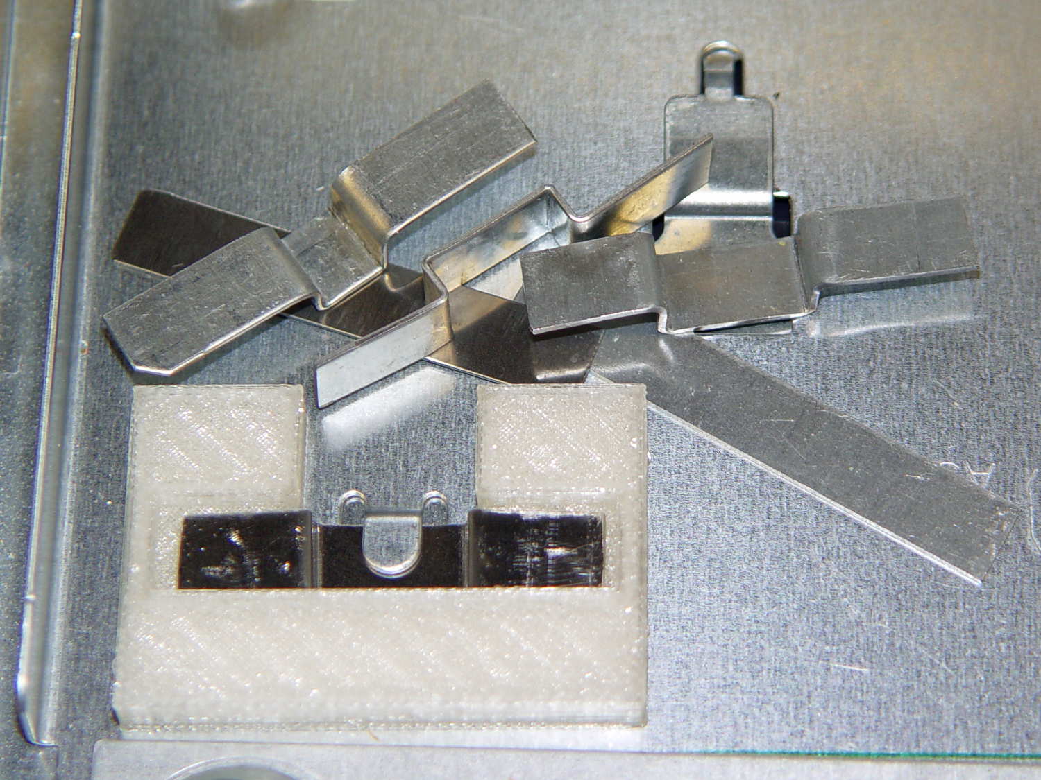
    Astonishingly, the socket slid firmly into its slot. I love it when that happens on the first try!

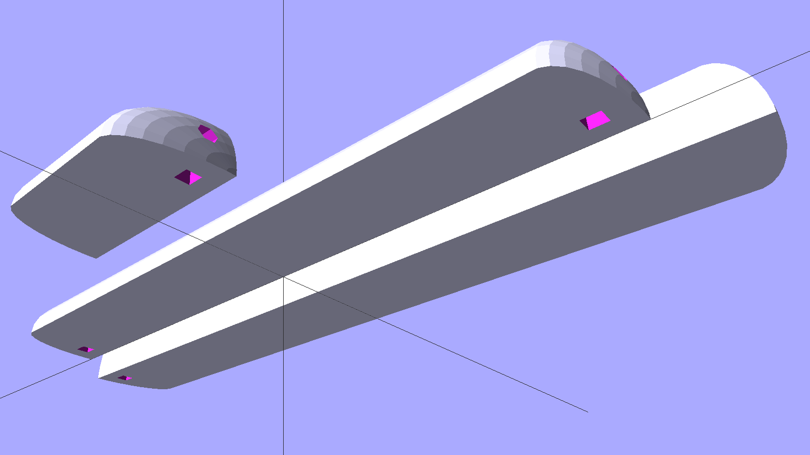
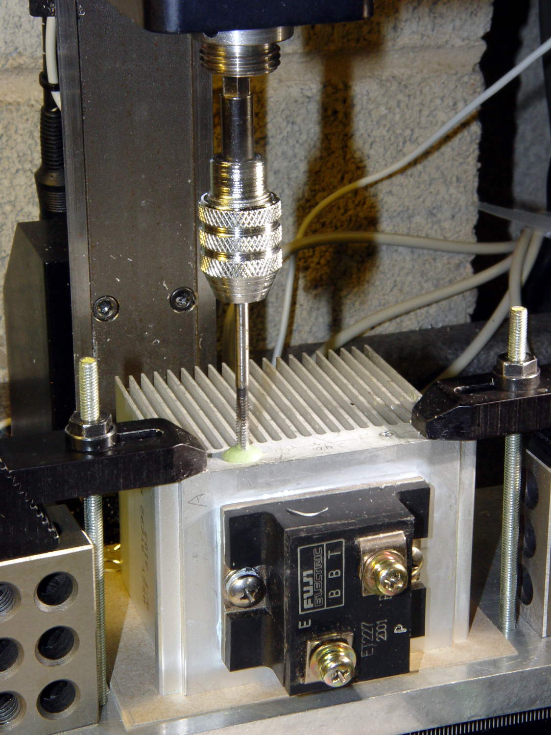
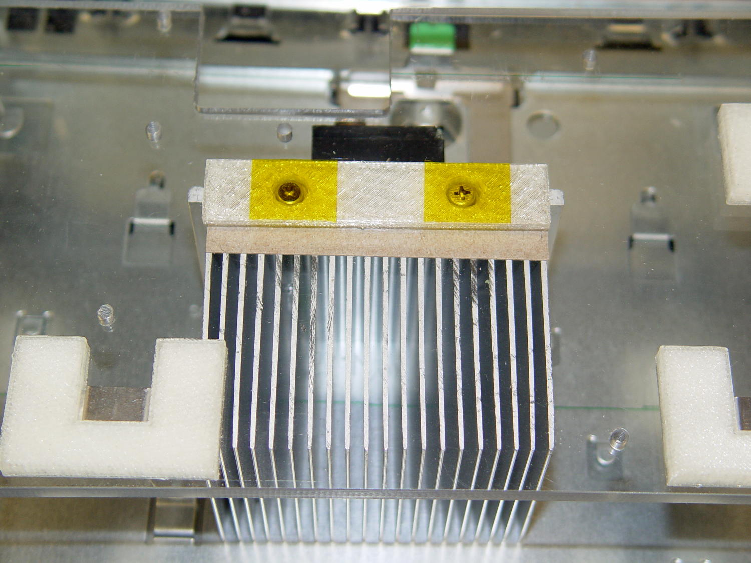
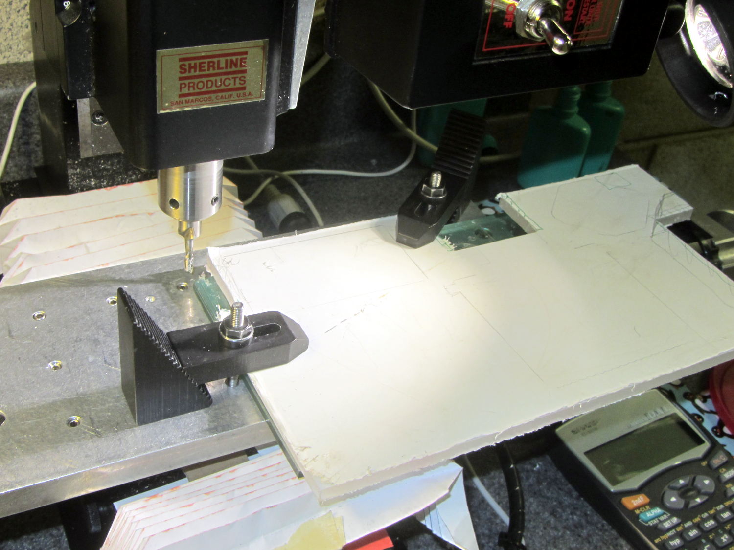
    The flat plate in front of the mount snaps into the chassis cutout to locate the 2-56 screw hole positions:

    PS2 Mount - drill guide
    PS2 Mount – drill guide

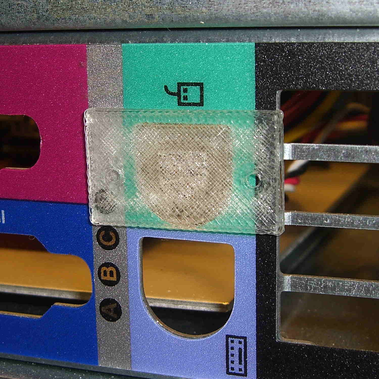
    The screws thread directly into the mount, with the holes tapped for 2-56. PLA isn’t all that strong, but there’s enough meat to hold the mount firmly enough for my simple purposes.

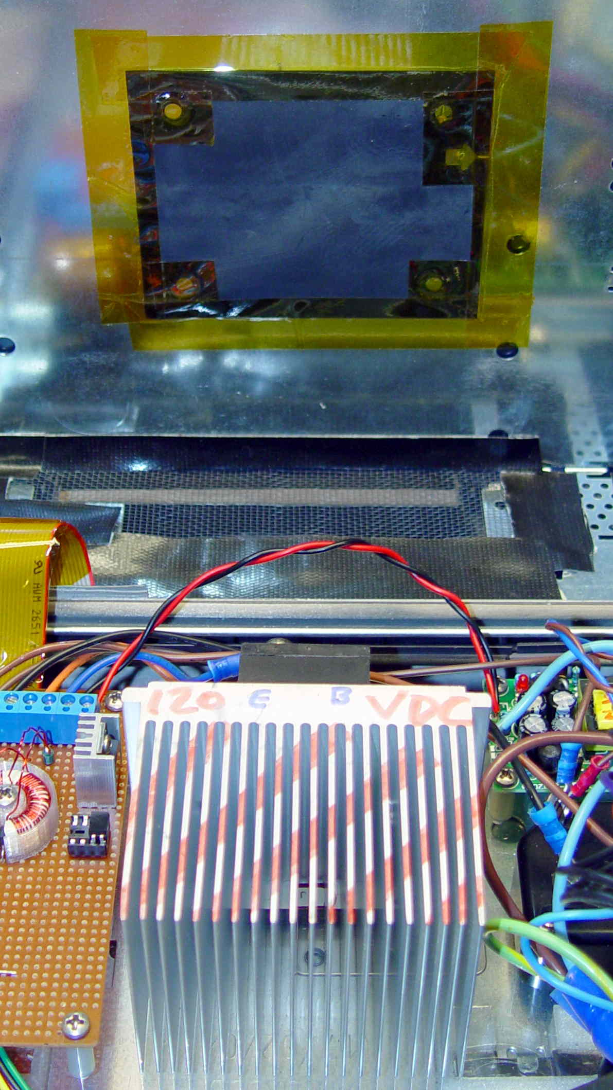
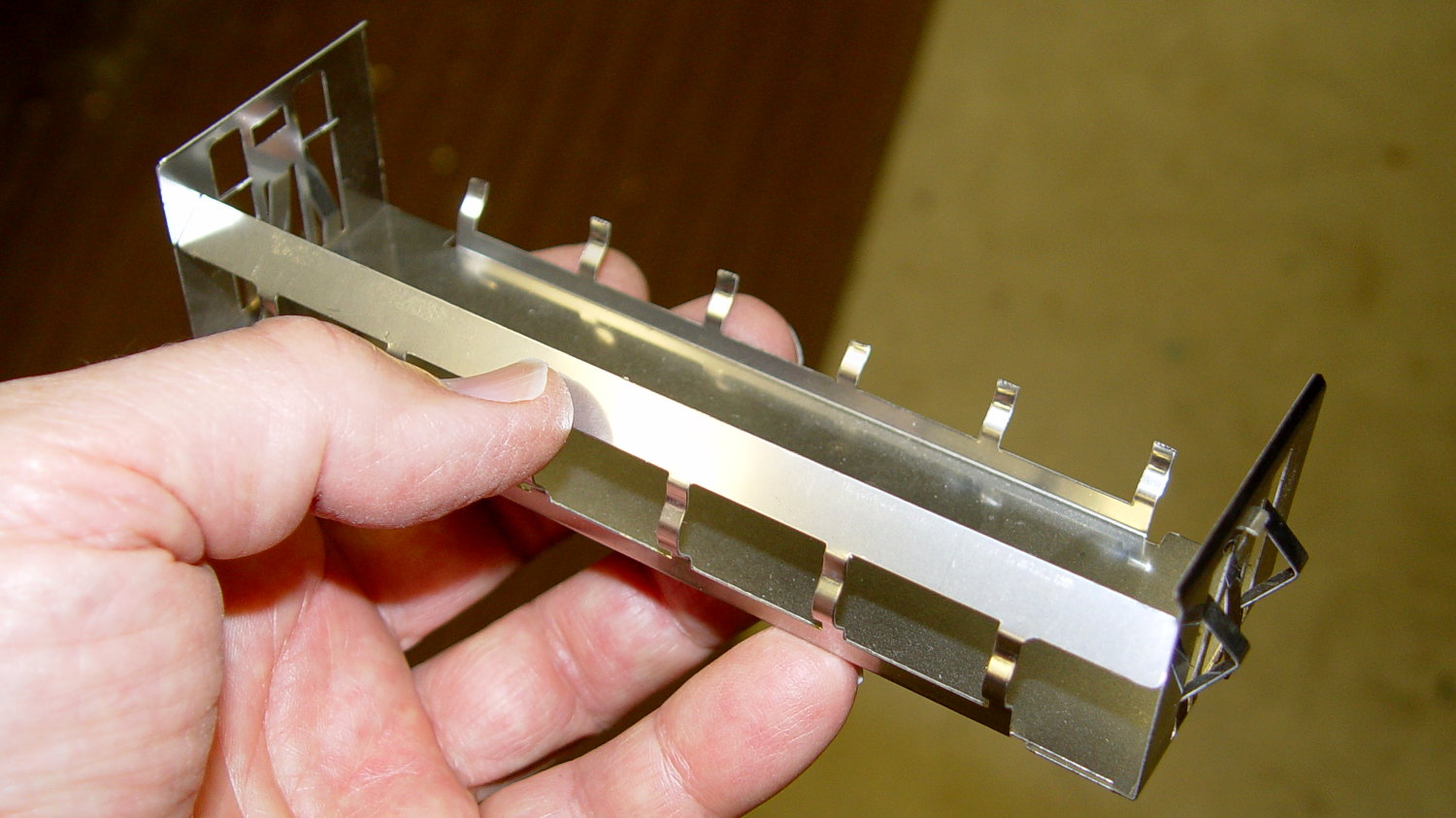
    And it looks pretty good, in a post-apocalyptic missing-windows sort of way:
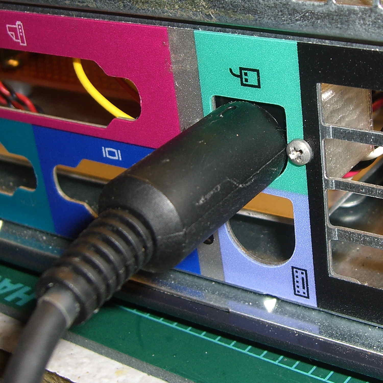
    PS2 Connector mount - in place
    PS2 Connector mount – in place

    That was easy…

    The OpenSCAD source code:

    // PS/2 Socket Mount
    // Ed Nisley - KE4ZNU - October 2014
    
    Layout = "Build";			// Build Socket Guide
    
    //- Extrusion parameters must match reality!
    
    ThreadThick = 0.20;
    ThreadWidth = 0.40;
    
    HoleWindage = 0.2;			// extra clearance
    
    Protrusion = 0.1;			// make holes end cleanly
    
    AlignPinOD = 1.70;			// assembly alignment pins: filament dia
    
    function IntegerMultiple(Size,Unit) = Unit * ceil(Size / Unit);
    
    //----------------------
    // Dimensions
    
    Socket = [14.1,13.3,13.0];	// PS/2 socket outline, minus tabs & wires on bottom
    
    Flange = 6.0;
    
    WallThick = IntegerMultiple(2.0,ThreadWidth);
    
    Mount = Socket + [2*Flange,WallThick,WallThick];
    
    ScrewTap = 1.90;			// 2-56 tap for machine screws
    
    ScrewOC = 19.0;
    
    echo(str("Screw OC: ",ScrewOC));
    
    ChassisHole = [13.0,13.0,1.0];
    GuideLayers = IntegerMultiple(0.5,ThreadThick);
    
    //----------------------
    // Useful routines
    
    module PolyCyl(Dia,Height,ForceSides=0) {			// based on nophead's polyholes
    
      Sides = (ForceSides != 0) ? ForceSides : (ceil(Dia) + 2);
    
      FixDia = Dia / cos(180/Sides);
    
      cylinder(r=(FixDia + HoleWindage)/2,
               h=Height,
               $fn=Sides);
    }
    
    module ShowPegGrid(Space = 10.0,Size = 1.0) {
    
      RangeX = floor(100 / Space);
      RangeY = floor(125 / Space);
    
    	for (x=[-RangeX:RangeX])
    	  for (y=[-RangeY:RangeY])
    		translate([x*Space,y*Space,Size/2])
    		  %cube(Size,center=true);
    
    }
    
    //-- Build the mount
    
    module SocketMount() {
    	
    	difference() {
    		translate([0,Mount[1]/2,Mount[2]/2])
    			cube(Mount,center=true);
    		
    		translate([0,Socket[1]/2,Socket[2]/2])
    			cube(Socket + [0,Protrusion,Protrusion],center=true);
    			
    		for (i=[-1,1])							// holes centered on socket, not mount
    			translate([i*ScrewOC/2,-Protrusion,Socket[2]/2])
    				rotate([-90,0,0])
    					rotate(180/6)
    						PolyCyl(ScrewTap,Mount[1] + 2*Protrusion,6);
    	}
    }
    
    //-- Totally ad-hoc drill guide to center holes on PS/2 cutout
    
    module DrillGuide() {
    	
    	union() {
    		intersection() {
    			translate([0,0,GuideLayers])
    				cube([2*Mount[0],2*Mount[1],2*GuideLayers],center=true);
    			translate([0,-Socket[2]/2,Mount[1]])
    				rotate([-90,0,0])
    					SocketMount();
    		}
    
    		translate([0,0,Protrusion])
    			linear_extrude(height=(3*GuideLayers - Protrusion)) {
    				circle(d=ChassisHole[0],$fn=8*4);
    				translate([-ChassisHole[0]/2,0])
    					square([ChassisHole[0],(ChassisHole[1] - ChassisHole[0]/2)],center=false);
    			}
    
    	}
    }
    
    
    //----------------------
    // Build it
    
    ShowPegGrid();
    
    if (Layout == "Socket")
    	SocketMount();
    
    if (Layout == "Guide")
    	DrillGuide();
    
    if (Layout == "Build") {
    	translate([0,-Mount[2],0])
    		DrillGuide();
    	translate([0,0,Mount[1]])
    		rotate([-90,0,0])
    			SocketMount();
    }
    
  • Kenmore 158 LED Strip Lighting: Now With Improved Wiring!

    It Has Been Decided (in that place where what is decided must be) to allow a single hole in the sewing machine’s front panel:

    Kenmore 158 - Front LED strip - wire routing
    Kenmore 158 – Front LED strip – wire routing

    The hole barely passes the 2 mm coaxial cable I’m misusing for the LED strips and is located where it:

    • Clears the machine’s metal frame to the upper left
    • Isn’t blocked by the knob’s mounting bracket to the lower right
    • Doesn’t snag the knob’s cam followers all over the insides
    • Lines up directly below the orange dot for pretty

    The first three of those happen behind the front panel, inside the frame, where you (well, I) can neither see nor measure the locations. I used a large outside caliper to get a feel for where the hole could possibly fit, then got it right on the first try!

    On the rear panel, it turns out that the presser foot lever doesn’t quite touch the top of its slot in the frame, so the cable for those LED strips can sneak through:

    Kenmore 158 - Rear LED strips - wire routing
    Kenmore 158 – Rear LED strips – wire routing

    Just inside that slot, the cable turns right, passes into the endcap, then goes upward to re-emerge at the top, inside the channel used for the old 120 VAC zip cord that powered the incandescent bulb in the endcap.

    I had some square cable clips lying around, so I used them, but the (yet to be designed) round versions will look better.

    The grody frame tells you this is the crash test dummy machine I’m using to verify things before installing them in Mary’s machine.

    The improved cable routing required different hole positions in the LED strip mounts:

    Strip Light Mount - Drilled cable routing
    Strip Light Mount – Drilled cable routing

    The internal wire route follows the original 120 VAC zip cord’s route from the bottom of the machine to the endcap (on the left), with the new branch for the front LEDs curving over the main shaft:

    Kenmore 158 - LED strips - internal wire routing
    Kenmore 158 – LED strips – internal wire routing

    The four-conductor ribbon cable also carries the supply voltage for the yet-to-be-built high intensity LED emitters in the end cap that will replace the 10 mm LEDs, with the ends terminated under the clamp in the middle. Those old steel wire clamps seem grossly oversized for the job, but that’s OK with me.

    The ribbon cable eases past that whirling crank arm, then passes through the frame to the outside cover under the handwheel, where it just barely clears the drive belts. A few zip ties hold it out of the way.

    The OpenSCAD source code offsets the wiring holes by 0.5 mm from the ends of the LED strips for easier wire bending, but is otherwise pretty much the same as before:

    // LED Strip Lighting Brackets for Kenmore Model 158 Sewing Machine
    // Ed Nisley - KE4ZNU - March 2014
    //  October 2014 - tweak endcap length & channel position
    
    Layout = "Build";			// Build Show Channels Strip
    
    //- Extrusion parameters must match reality!
    //  Print with 2 shells and 3 solid layers
    
    ThreadThick = 0.20;
    ThreadWidth = 0.40;
    
    HoleWindage = 0.2;			// extra clearance
    
    Protrusion = 0.1;			// make holes end cleanly
    
    AlignPinOD = 1.70;			// assembly alignment pins: filament dia
    
    inch = 25.4;
    
    function IntegerMultiple(Size,Unit) = Unit * ceil(Size / Unit);
    
    //----------------------
    // Dimensions
    
    LEDSegment = [25.0,10.0,3.0];		//  size of each LED segment
    SEGLENGTH = 0;
    SEGWIDTH = 1;
    SEGHEIGHT = 2;
    
    WireChannel = 3.0;				// wire routing channel diameter
    
    StripHeight = 12.0;				// sticky tape width
    
    DefaultLayout = [1,2,"Wire","NoWire"];
    NUMSEGS = 0;
    NUMSTRIPS = 1;
    WIRELEFT = 2;
    WIRERIGHT = 3;
    
    EndCapSides = 8*4;				// endcap smoothness
    EndCapShim = 0.5;				// additional space for easier wire bending
    
    function EndCapSize(Layout) = [(2*WireChannel + EndCapShim),Layout[NUMSTRIPS]*LEDSegment[SEGWIDTH],StripHeight];
    
    //----------------------
    // Useful routines
    
    module PolyCyl(Dia,Height,ForceSides=0) {			// based on nophead's polyholes
    
      Sides = (ForceSides != 0) ? ForceSides : (ceil(Dia) + 2);
    
      FixDia = Dia / cos(180/Sides);
    
      cylinder(r=(FixDia + HoleWindage)/2,
               h=Height,
               $fn=Sides);
    }
    
    module ShowPegGrid(Space = 10.0,Size = 1.0) {
    
      RangeX = floor(100 / Space);
      RangeY = floor(125 / Space);
    
    	for (x=[-RangeX:RangeX])
    	  for (y=[-RangeY:RangeY])
    		translate([x*Space,y*Space,Size/2])
    		  %cube(Size,center=true);
    
    }
    
    //-- The negative space used to thread wires into the endcap
    
    module MakeWireChannel(Layout = DefaultLayout,Which = "Left") {
    
    	EndCap = EndCapSize(Layout);	// radii of end cap spheroid
    
    	HalfSpace = EndCap[0] * ((Which == "Left") ? 1 : -1);
    
    	render(convexity=2)
    	translate([0,LEDSegment[SEGWIDTH]/2,0])
    		intersection() {
    			union() {
    				cube([2*WireChannel,WireChannel,EndCap[2]],center=true);
    				translate([-2*EndCap[0],0,EndCap[2]/2])
    					rotate([0,90,0]) rotate(180/6)
    						PolyCyl(WireChannel,4*EndCap[0],6);
    			}
    			translate([HalfSpace,0,(EndCap[2] - Protrusion)]) {
    				cube(2*EndCap,center=true);
    			}
    		}
    }
    
    //-- The whole strip, minus wiring channels
    
    module MakeStrip(Layout = DefaultLayout) {
    
    	EndCap = EndCapSize(Layout);	// radii of end cap spheroid
    
    	BarLength = Layout[NUMSEGS] * LEDSegment[SEGLENGTH];				// central bar length
    
    	echo(str("Strip OAL: ",BarLength + 2*EndCap[SEGLENGTH]));
    
    	hull()
    		difference() {
    			for (x = [-1,1])						// endcaps as spheroids
    				translate([x*BarLength/2,0,0])
    					resize(2*EndCap) rotate([0,90,0]) sphere(1.0,$fn=EndCapSides);
    			translate([0,0,-EndCap[2]])
    				cube([2*BarLength,3*EndCap[1],2*EndCap[2]],center=true);
    			translate([0,-EndCap[1],0])
    				cube([2*BarLength,2*EndCap[1],3*EndCap[2]],center=true);
    		}
    
    }
    
    //-- Cut wiring channels out of strip
    
    module MakeMount(Layout = DefaultLayout) {
    
    	BarLength = Layout[NUMSEGS] * LEDSegment[SEGLENGTH];
    
    	difference() {
    		MakeStrip(Layout);
    		if (Layout[WIRELEFT] == "Wire")
    			translate([(BarLength/2 + EndCapShim),0,0])
    				MakeWireChannel(Layout,"Left");
    		if (Layout[WIRERIGHT] == "Wire")
    			translate([-(BarLength/2 + EndCapShim),0,0])
    				MakeWireChannel(Layout,"Right");
    	}
    }
    
    //- Build it
    
    ShowPegGrid();
    
    if (Layout == "Channels") {
    	translate([ (2*WireChannel + 1.0),0,0]) MakeWireChannel(DefaultLayout,"Left");
    	translate([-(2*WireChannel + 1.0),0,0]) MakeWireChannel(DefaultLayout,"Right");
    }
    
    if (Layout == "Strip") {
    	MakeStrip(DefaultLayout);
    }
    
    if (Layout == "Show") {
    	MakeMount(DefaultLayout);
    }
    
    if (Layout == "Build") {
    
    	if (false) {					// original no-drill wiring
    		translate([0,(3*LEDSegment[SEGWIDTH]),0]) MakeMount([1,2,"Wire","Wire"]);		// rear left side, vertical
    		translate([0,0,0]) MakeMount([5,2,"Wire","NoWire"]);				// rear top, across arm
    		translate([0,-(3*LEDSegment[SEGWIDTH]),0]) MakeMount([6,2,"NoWire","Wire"]);	// front top, across arm
    	}
    
    	if (true) {						// front: drill panel, rear: route through foot lift lever
    		translate([0,(3*LEDSegment[SEGWIDTH]),0])
    			MakeMount([1,2,"NoWire","Wire"]);				// rear left side, vertical
    		translate([0,0,0])
    			MakeMount([5,2,"Wire","Wire"]);					// rear top, across arm
    		translate([0,-(1*LEDSegment[SEGWIDTH]),0])
    			rotate(180)
    			MakeMount([6,2,"NoWire","Wire"]);				// front top, across arm
    	}
    }
    
  • Search Engine Optimization: Replacement Shelf Bracket Whirlpool Freezer

    If I were selling those brackets, I’d be rich:

    Search Engine Optimization - Freezer Shelf Bracket
    Search Engine Optimization – Freezer Shelf Bracket

    Now, that looks like Search Engine Optimization it is to die for! Google will give you a different set of pictures, but I own that all-important top row.

    Alas, anybody can just print their own…

  • Kenmore 158: LED Strip Light Cable Clips

    Commercial LED strip lights for sewing machines mount their cables with little stick-on anchors and cable ties. I wasn’t happy with the cable tie thing and finally figured this out:

    Kenmore 158 - LED strip light cable clips
    Kenmore 158 – LED strip light cable clips

    The clips have that size & shape because they fit exactly atop some pre-cut foam squares from the Tape Lookaside Buffer:

    LED strip light cable clips
    LED strip light cable clips

    You can see the shape better in the solid model:

    LED Cable Clips
    LED Cable Clips

    The central bollard has a slight taper to retain the cable, the quarter-posts are straight, and they’re both twice the cable diameter tall. The clearance between the center and corner posts at the top matches the cable diameter, so there’s a bit of bending room at the bottom, and, with the cable bent around the center, it won’t fall out on its own.

    The cute coaxial cable I’m misusing for the LED strips measures just shy of 2 mm, making these into little bitty things. The corner posts seem surprisingly strong, despite 3D printing’s reputation for crappy quality; I haven’t been able to break one off with more effort than seemed warranted.

    The OpenSCAD source code:

    // LED Cable Clips
    // Ed Nisley - KE4ZNU - October 2014
    
    //- Extrusion parameters must match reality!
    
    ThreadThick = 0.20;
    ThreadWidth = 0.40;
    
    HoleWindage = 0.2;			// extra clearance
    
    Protrusion = 0.1;			// make holes end cleanly
    
    AlignPinOD = 1.70;			// assembly alignment pins: filament dia
    
    function IntegerMultiple(Size,Unit) = Unit * ceil(Size / Unit);
    
    //----------------------
    // Dimensions
    
    Base = [12.0,12.0,IntegerMultiple(2.0,ThreadThick)];	// base over sticky square
    
    CableOD = 2.0;
    
    BendRadius = 3.0;
    
    Bollard = [BendRadius,(sqrt(2)*Base[0]/2 - CableOD - BendRadius),2*CableOD];
    B_BOT = 0;
    B_TOP = 1;
    B_LEN = 2;
    
    NumSides = 5*4;
    
    //----------------------
    // Useful routines
    
    module PolyCyl(Dia,Height,ForceSides=0) {			// based on nophead's polyholes
    
      Sides = (ForceSides != 0) ? ForceSides : (ceil(Dia) + 2);
    
      FixDia = Dia / cos(180/Sides);
    
      cylinder(r=(FixDia + HoleWindage)/2,
               h=Height,
               $fn=Sides);
    }
    
    module ShowPegGrid(Space = 10.0,Size = 1.0) {
    
      RangeX = floor(100 / Space);
      RangeY = floor(125 / Space);
    
    	for (x=[-RangeX:RangeX])
    	  for (y=[-RangeY:RangeY])
    		translate([x*Space,y*Space,Size/2])
    		  %cube(Size,center=true);
    
    }
    
    //----------------------
    // Build it
    
    ShowPegGrid();
    
    intersection() {
    	translate([0,0,(Base[2] + Bollard[2])/2])			// overall XYZ outline
    		cube(Base + [0,0,Bollard[2]],center=true);
    	
    	union() {
    		translate([0,0,Base[2]/2])						// oversize mount base
    			scale([2,2,1])
    				cube(Base,center=true);
    				
    		for (i=[-1,1] , j=[-1,1]) {						// corner bollards
    			translate([i*Base[0]/2,j*Base[1]/2,(Base[2] - Protrusion)])
    				rotate(180/NumSides)
    				cylinder(r=Bollard[B_BOT],h=(Bollard[B_LEN] + Protrusion),center=false,$fn=NumSides);
    
    		translate([0,0,(Base[2] - Protrusion)])			// center tapered bollard
    			cylinder(r1=Bollard[B_BOT],r2=Bollard[B_TOP],h=(Bollard[B_LEN] + Protrusion),center=false,$fn=NumSides);
    		}
    	}
    }
    

    Now that I think of it, maybe a round clip would look nicer. The central bollard would stay, but the circular outside rim could have three cutouts. When these fall off, I’ll give that a try.

    They may be square and clunky, but they look much better than Gorilla Tape…


  • ATX Power Supply: System Board Connector Bracket

    The GX270 case contains a perfectly serviceable ATX power supply that can power all the bits & pieces that don’t run directly from the AC power line. I torched the connector off the system board, but there’s no practical way to mount it standing up through the prototyping board I’m using for the low voltage electronics. This bracket surrounds that connector and holds it at right angles to the board, with a pair of screws clamping it in place:

    ATX Connector Bracket - front
    ATX Connector Bracket – front

    I invoked the shade of Willy McCoy, slashed the outside of the connector with a razor knife, buttered it up with epoxy, and shoved it flush inside the adapter. That messy epoxy bead around the joint should prevent it from pulling out to the front:

    ATX Connector Bracket - rear
    ATX Connector Bracket – rear

    The solid model looks like you’d expect:

    ATX Connector Mount
    ATX Connector Mount

    In the unlikely event you need one, make sure the slot clears the locking clip on your ATX connector, as they differ between (at least) the 20 and 24 pin versions. This is actually a split 20/24 connector, with the smaller connector terminating elsewhere to power the LED strips.

    The OpenSCAD source code:

    // ATX power supply connector mounting bracket
    // Ed Nisley - KE4ZNU - September 2014
    
    //- Extrusion parameters must match reality!
    
    ThreadThick = 0.20;
    ThreadWidth = 0.40;
    
    HoleWindage = 0.2;			// extra clearance
    
    Protrusion = 0.1;			// make holes end cleanly
    
    AlignPinOD = 1.70;			// assembly alignment pins: filament dia
    
    function IntegerMultiple(Size,Unit) = Unit * ceil(Size / Unit);
    
    //----------------------
    // Dimensions
    
    Screw = [3.5,7.0];						// mounting screws
    OD = 0;
    HEAD_OD = 1;
    
    Wall = 3.0;
    
    ATX = [43.5,9.75,12.0];					// connector outline
    
    Shell = ATX + [2*(2*Wall + Screw[OD]),2*Wall,0.0];	// mount outline
    
    Latch = [5.0,5.0,7.0];							// latch overlay
    
    ScrewOC = ATX[0] + Screw[OD] + 2*Wall;
    
    echo(str("Screw OC: ",ScrewOC," mm"));
    
    //----------------------
    // Useful routines
    
    module PolyCyl(Dia,Height,ForceSides=0) {			// based on nophead's polyholes
    
      Sides = (ForceSides != 0) ? ForceSides : (ceil(Dia) + 2);
    
      FixDia = Dia / cos(180/Sides);
    
      cylinder(r=(FixDia + HoleWindage)/2,
               h=Height,
               $fn=Sides);
    }
    
    module ShowPegGrid(Space = 10.0,Size = 1.0) {
    
      RangeX = floor(100 / Space);
      RangeY = floor(125 / Space);
    
    	for (x=[-RangeX:RangeX])
    	  for (y=[-RangeY:RangeY])
    		translate([x*Space,y*Space,Size/2])
    		  %cube(Size,center=true);
    
    }
    
    ShowPegGrid();
    
    difference() {
    	translate([0,0,Shell[2]/2])						// mount shell
    		cube(Shell,center=true);
    	translate([0,0,ATX[2]/2])					// connector shell
    		cube(ATX + [0,0,2*Protrusion],center=true);
    
    	translate([0,(Latch[1]/2 + ATX[1]/2 - Protrusion),(-Latch[2]/2 + Shell[2])])
    		cube(Latch + [0,Protrusion,Protrusion],center=true);
    
    	for (i=[-1,1])
    		translate([i*ScrewOC/2,(Shell[1]/2 + Protrusion),Shell[2]/2])
    			rotate([90,0,0])
    				PolyCyl(Screw[OD],(Shell[1] + 2*Protrusion));
    
    }
    
  • ET227 Transistor: Monster Heatsink Mounting

    Back in the day, heatsinks like this sat atop Moah Powah Pentium CPUs:

    ET227 transistor on heatsink
    ET227 transistor on heatsink

    I picked it because the hulking ET227 transistor fit neatly on its backside, it seemed capable of handling 30 to 50 W of power, and I have several of them in the Big Box o’ Heatsinks. No careful thermal analysis was involved…

    Mounting it on the polycarbonate sheet inside the repurposed GX270 case involved drilling & tapping a pair of 6-32 holes in one side:

    ET227 Heatsink - tapping
    ET227 Heatsink – tapping

    That’s not rigid tapping on a Sherline, it’s aligning a hand-turned tap in the spindle bore. Sorry.

    And, yeah, you’re not supposed to leave the semiconductors mounted when you’re drilling the heatsink. I figure there’s nothing I can possibly do without using a hammer that will bother that transistor in the slightest. What, me worry?

    The transistor collector runs at line voltage, which means the entire heatsink will pose a lethal shock hazard. I thought about isolating the collector and failed to come up with anything I’d trust to be both thermally conductive and electrically insulating over the long term; the screw heads must be isolated from the collector plate, too.

    The screws stick out below the polycarbonate sheet, just above the grounded EMI shell lining the case, so I flattened them a bit:

    ET227 Heatsink - mounting screws
    ET227 Heatsink – mounting screws

    The simple rectangular strip to the rear of the chassis mounting clips is just slightly thicker than the screw heads, so they can’t possibly contact the case:

    Chassis Clips
    Chassis Clips

    It gets glued to the underside of the nearly invisible sheet:

    ET227 heatsink - gluing screw shield
    ET227 heatsink – gluing screw shield

    With Kapton tape over the heads, Just In Case:

    ET227 Heatsink - mounted
    ET227 Heatsink – mounted

    It makes a nice linear counterpoint to the jumble of AC interface wiring:

    AC Interface Chassis
    AC Interface Chassis

    The insulating sheet on the case lid came from the bottom of the original GX270 system board, where I think it served much the same purpose. It’s surely not rated for AC line voltages, but the thought must count for something:

    AC Interface Chassis
    AC Interface Chassis

    More of the parts are flying in formation…

  • AC Interface Chassis Mounting Clips

    The Dell GX270 system board mounts on a tray, latching into small tabs, with a single screw locking it in place. The tray then slides into the metal EMI shield / case, latching onto more tabs, with a spring-loaded pair of tabs snapping into a slot under the green latch:

    Optiplex GX270 - system board tray
    Optiplex GX270 – system board tray

    All that is well and good for a mass-production PC system board, but poses a problem for mounting anything else: there’s no room for screw heads below the tray, adhesives really don’t bond to slightly flexible aluminum sheets, and I definitely can’t do large-scale precision metal bending.

    So a cheat seems in order. The general idea is to support a 6 mm polycarbonate sheet on clips that slide under the small tabs along the front, support the sheet on the rear tabs, and secure it with the screw. That’s thick enough to allow tapping holes for mounting screws, so everything else can mount to the sheet.

    The sheet fits around the power supply on the right, protrudes over the rear of the tray to the back of the case (with a recess around the green latch), and clears the hinge assembly on the left. There are no dimensions, as it’s all done by eye with the Joggy Thing.

    AC Chassis Shaping
    AC Chassis Shaping

    A drive bay EMI plug from a long-discarded PC provided some nice springy steel strips that slide neatly under those tray tabs:

    Drive EMI shield
    Drive EMI shield

    That actually took a bit of trial-and-error:

    AC Chassis mounting brackets - practice makes perfect
    AC Chassis mounting brackets – practice makes perfect

    My first attempts used slightly thicker steel that didn’t fit nearly as well, plus I wasn’t quite sure how wide they should be.

    As with nearly all plastic doodads around here, the white plastic mounting clips / brackets come from the M2:

    Chassis Clips
    Chassis Clips

    The two brackets in the middle of the solid model slide around the tabs at the rear corners of the tray and capture the bent-over top section below the polycarbonate sheet.

    The strip in the rear goes around the screws holding the heatsink to the sheet; more on that later.

    The PLA brackets get themselves glued to the sheet with IPS #4 solvent adhesive, a hellish mixture of chlorinated hydrocarbons that attacks most plastics with gleeful enthusiasm. I positioned the brackets on the tray, slobbered adhesive on their tops, slapped the polycarbonate sheet in place, and applied clamps:

    AC Chassis - gluing bracket blocks
    AC Chassis – gluing bracket blocks

    The final bonds weren’t as uniform as I’d like, but they seem rugged enough. The lip along the rear of the tray was slightly higher on the left edge, which may have interfered with the clamping pressure; it’s obviously not a controlled dimension.

    The tapped holes in the sheet accommodate screws for various bits & pieces.

    All in all, that worked out pretty well…

    The OpenSCAD source code:

    // AC Interface sheet mounting brackets
    // Ed Nisley - KE4ZNU - August 2014
    
    Layout = "Build";		// FrontClip RearClip HeatSink Build
    
    Gap = 5.0;					// between Build objects
    
    //- Extrusion parameters must match reality!
    
    ThreadThick = 0.20;
    ThreadWidth = 0.40;
    
    HoleWindage = 0.2;			// extra clearance
    
    Protrusion = 0.1;			// make holes end cleanly
    
    AlignPinOD = 1.70;			// assembly alignment pins: filament dia
    
    function IntegerMultiple(Size,Unit) = Unit * ceil(Size / Unit);
    
    //----------------------
    // Dimensions
    
    FC_Block = [45.0,30.0,IntegerMultiple(5.6,ThreadThick)];
    FC_Retainer = [15.5,9.0,3.0,15.0];					// central section: L,W,H, inset from front
    
    RC_Block = [30.0,25.0,IntegerMultiple(5.6,ThreadThick)];
    RC_RecessOffset = [9.0,5.0,IntegerMultiple(4.8,ThreadThick)];	// X,Y,thickness
    RC_SlotWidth = 2.5;
    
    HS_Insulation = [80.0,16.0,2.5];
    HS_Hole = [8.0,40.0];					// screw clearance dia,on-center
    
    //----------------------
    // Useful routines
    
    module PolyCyl(Dia,Height,ForceSides=0) {			// based on nophead's polyholes
    
      Sides = (ForceSides != 0) ? ForceSides : (ceil(Dia) + 2);
    
      FixDia = Dia / cos(180/Sides);
    
      cylinder(r=(FixDia + HoleWindage)/2,
               h=Height,
               $fn=Sides);
    }
    
    module ShowPegGrid(Space = 10.0,Size = 1.0) {
    
      RangeX = floor(100 / Space);
      RangeY = floor(125 / Space);
    
    	for (x=[-RangeX:RangeX])
    	  for (y=[-RangeY:RangeY])
    		translate([x*Space,y*Space,Size/2])
    		  %cube(Size,center=true);
    
    }
    
    //----------------------
    // Front clips
    
    module FrontClip() {
    
    	difference() {
    		translate([0,0,FC_Block[2]/2])
    			cube(FC_Block,center=true);
    
    		translate([0,(FC_Retainer[3] - FC_Block[1]/2),(FC_Retainer[2] + FC_Block[2]/2)])
    			cube([(FC_Block[0] - 12*ThreadWidth),FC_Retainer[1],FC_Block[2]],center=true);
    
    		translate([0,FC_Retainer[3] - FC_Retainer[1]/2,FC_Block[2]/2])
    			cube([FC_Retainer[0],FC_Block[1],2*FC_Block[2]],center=true);
    	}
    
    }
    
    //----------------------
    // Rear clips
    
    module RearClip(Hand="Left") {
    
    HandSign = (Hand == "Left") ? -1 : 1;
    
    	difference() {
    		translate([0,0,RC_Block[2]/2])
    			cube(RC_Block,center=true);
    
    		translate([0,RC_RecessOffset[1],RC_RecessOffset[2] + RC_Block[2]/2])
    			cube([RC_Block[0] - 2*RC_RecessOffset[0],
    				  RC_Block[1],
    				  RC_Block[2]],center=true);
    
    		translate([HandSign*(RC_Block[0]/2 - RC_RecessOffset[0]),
    				   RC_RecessOffset[1],
    				   0])
    			cube([RC_SlotWidth,RC_Block[1],3*RC_Block[2]],center=true);
    
    	}
    
    }
    
    //----------------------
    // Heatsink bumper
    
    module HeatSink() {
    
    	difference() {
    		translate([0,0,HS_Insulation[2]/2])
    			cube(HS_Insulation,center=true);
    
    	for (x=[-1,1])
    		translate([x*HS_Hole[1]/2,0,-HS_Insulation[2]])
    			PolyCyl(HS_Hole[0],3*HS_Insulation[2],8);
    	}
    
    }
    
    ShowPegGrid();
    
    if (Layout == "FrontClip") {
    	FrontClip();
    }
    
    if (Layout == "RearClip") {
    	RearClip("Left");
    }
    
    if (Layout == "HeatSink") {
    	HeatSink();
    }
    
    if (Layout == "Build") {
    	for (x=[-1,1]) {
    		translate([x*(Gap + FC_Block[0])/2,(Gap + FC_Block[1])/2,0])
    			FrontClip();
    		translate([x*(Gap + RC_Block[0])/2,-(Gap + RC_Block[1])/2,0])
    			RearClip((x == -1) ? "Left" : "Right");
    	}
    	translate([0,-(RC_Block[1] + HS_Insulation[1]/2 + 3*Gap/2),0])
    		HeatSink();
    }