The Smell of Molten Projects in the Morning

Ed Nisley's Blog: Shop notes, electronics, firmware, machinery, 3D printing, laser cuttery, and curiosities. Contents: 100% human thinking, 0% AI slop.

Tag: M2

Using and tweaking a Makergear M2 3D printer

  • Badge Lanyard Reel Mount

    A certain young engineer of my acquaintance now carries an ID badge and, so I hear, works in a PCB design & test venue. Seeing as how her favorite color is purple, this seemed appropriate:

    Badge Lanyard Reel - front - overall
    Badge Lanyard Reel – front – overall

    The guts came from Circuit Breaker Labs in the form of a recycled PCB trapped in acrylic resin atop a plastic housing with a spring-loaded reel inside.

    It arrived with a plastic bullet at the end of the lanyard:

    Badge Lanyard Reel - plastic bullet link
    Badge Lanyard Reel – plastic bullet link

    Which I immediately replaced with brass, because Steampunk:

    Badge Lanyard Reel - bullet cross-drill
    Badge Lanyard Reel – bullet cross-drill

    That made the plastic housing look weak, so, in a series of stepwise refinements, I conjured a much better case from the vasty digital deep:

    Badge Lanyard Reel - iterations
    Badge Lanyard Reel – iterations

    All of the many, many critical dimensions lie inside the case, where they can’t be measured accurately, so each of those iterations could improve only one or two features. The absolutely wonderful thing about OpenSCAD is having it regenerate the whole model after loosening, say, the carabiner slot by two thread thicknesses; you can do that with a full-on relational CAD drawing, but CAD drawings always seems like a lot of unnecessary work if I must figure out the equations anyway.

    The back sports my favorite Hilbert Curve infill with a nicely textured finish:

    Badge Lanyard Reel - rear - oblique
    Badge Lanyard Reel – rear – oblique

    It’d surely look better in solid brass with Hilbert curve etching.

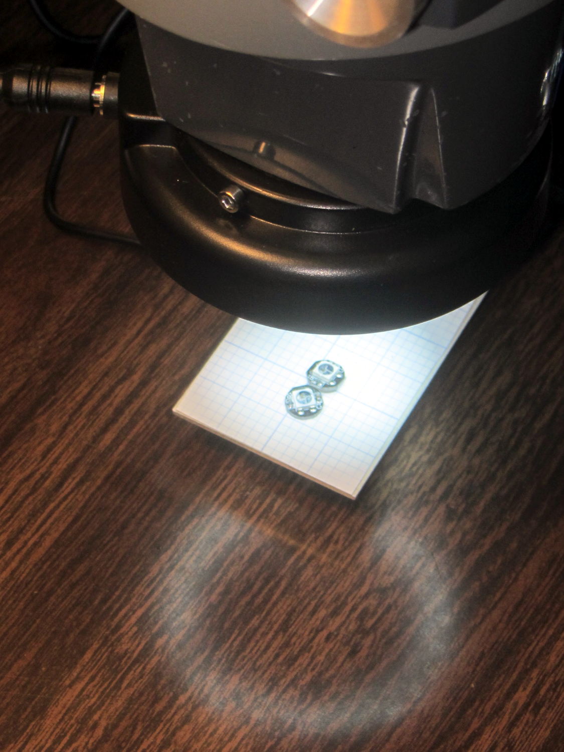
    Black PETG doesn’t photograph well, but at least you can see the M2 brass inserts:

    Badge Lanyard Reel - lower interior
    Badge Lanyard Reel – lower interior

    The first prototype showed the inserts needed far more traction than the usual reamed holes could provide, so I added internal epoxy grooves in each hole:

    Badge Lanyard Reel Mount - show
    Badge Lanyard Reel Mount – show

    Recessing the screw heads into the top plate made them more decorative and smoother to the touch. Button-head screws would be even smoother, but IMO didn’t look quite as bold.

    After seeing how well the grooves worked, I must conjure a module tabulating all the inserts on hand and automagically generating the grooves.

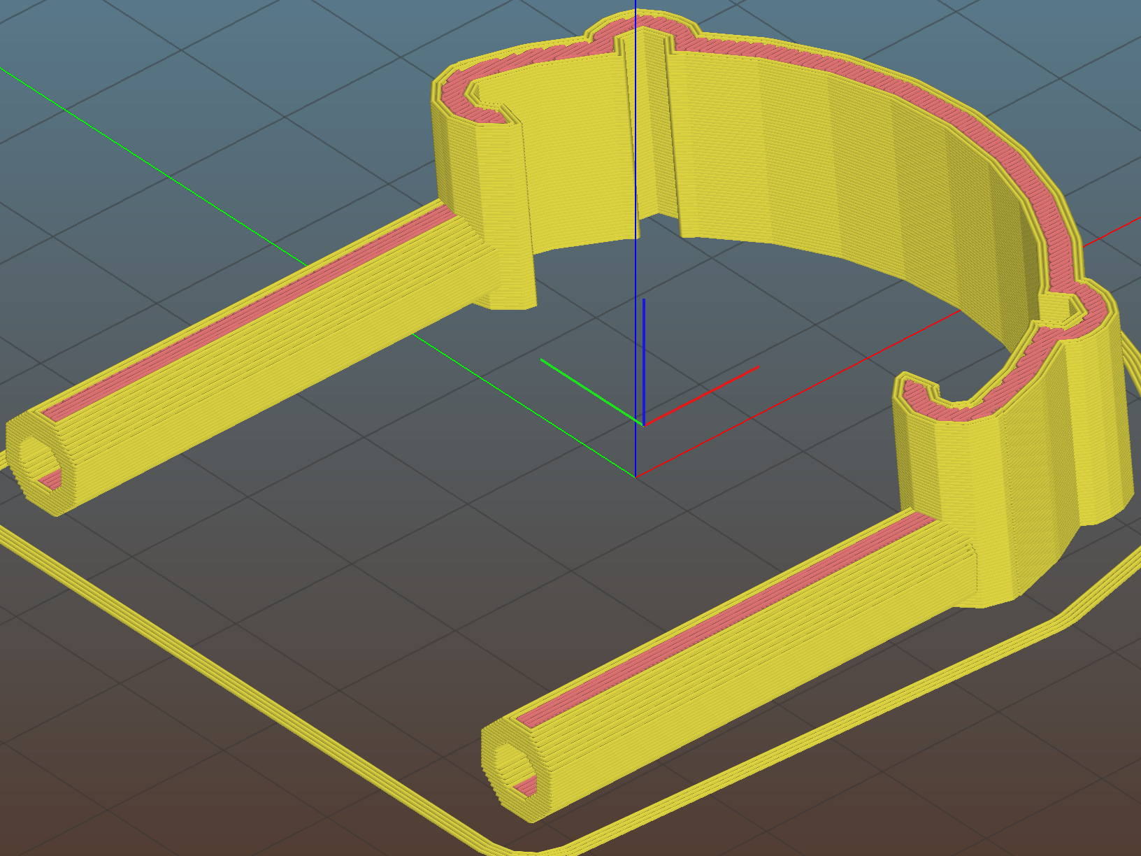
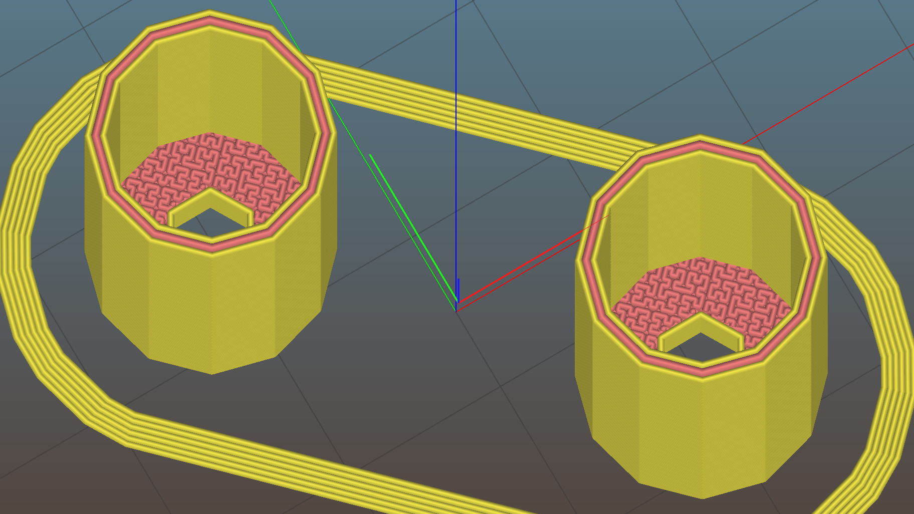
    The yellow star holds up the roof of the reel recess in the build layout:

    Badge Lanyard Reel Mount - build layout - bottom
    Badge Lanyard Reel Mount – build layout – bottom

    Slic3r produced the rest of the support material for the carabiner exit slot:

    Badge Lanyard Reel Mount - bottom - Slic3r support
    Badge Lanyard Reel Mount – bottom – Slic3r support

    Those two support lumps on the right don’t actually support anything, but tweaking the support settings to disable them also killed the useful support on the left; come to find out Slic3r’s modifier meshes don’t let you disable support generation.

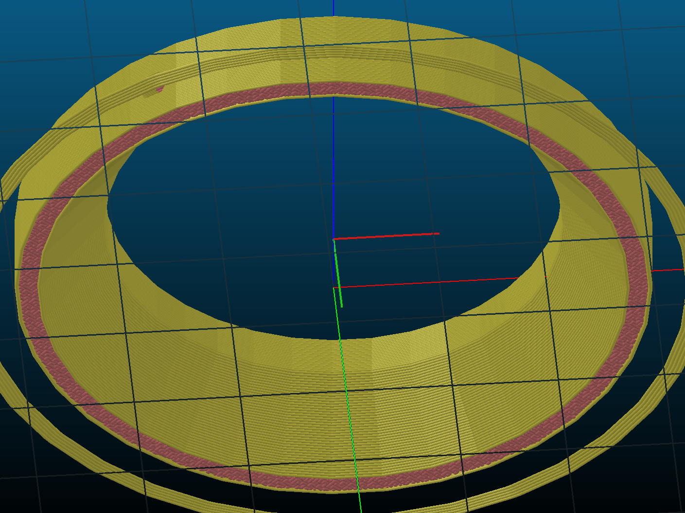
    The top plate required support all the way around the inside of the bezel:

    Badge Lanyard Reel Mount - top - Slic3r support
    Badge Lanyard Reel Mount – top – Slic3r support

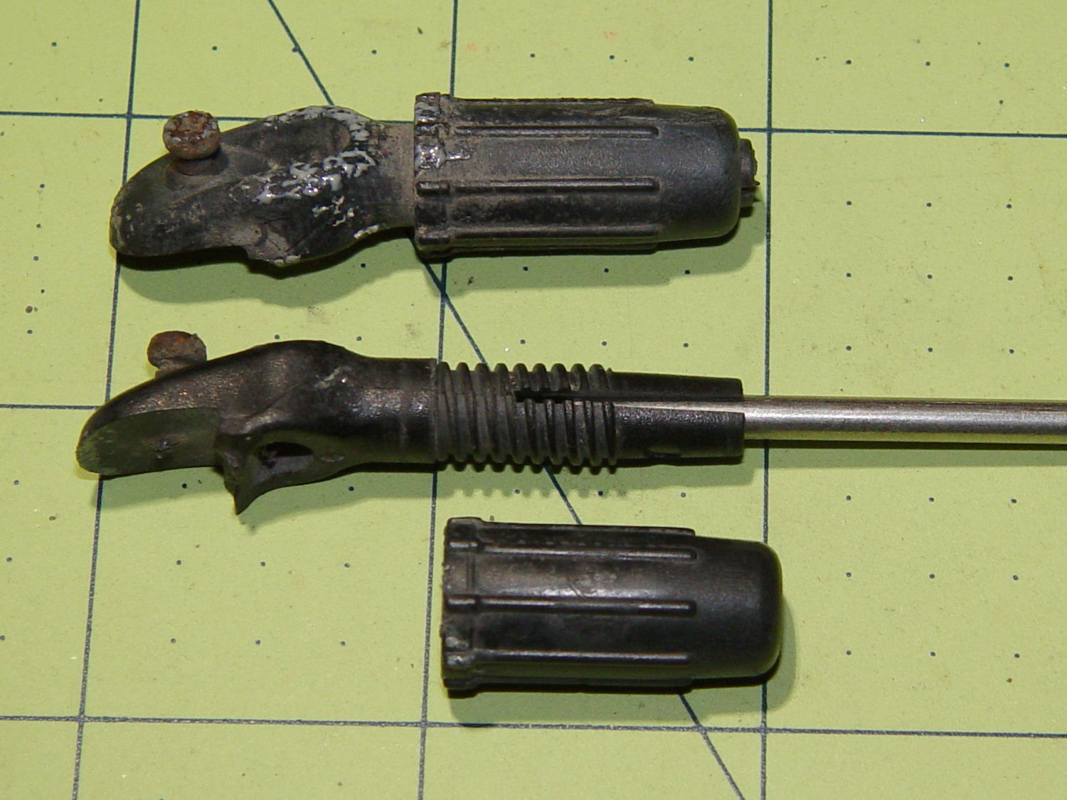
    I carved the original plastic housing in half, roughly along its midline, and discarded the bottom section with the belt clip (it’s on the far left of the scrap pile). The top section, with PCB firmly affixed, holds the lanyard reel and anchors the retracting spring in a central slotted peg. No pictures of that, as it’s either a loose assembly of parts or a spring-loaded bomb and I am not taking it apart again.

    The lanyard passes through an eyelet that pays it out to the rotating reel. I’d definitely do that differently, were I building it from scratch, because mounting the eyelet in exactly the proper position to prevent the lanyard from stacking up on the reel and jamming against the inside of the housing turned out to be absolutely critical and nearly impossible.

    The top plate presses the original housing against the carabiner, with the cut-off section inside the carabiner’s circular embrace, which just barely worked: the PCB bezel is a millimeter smaller than the shoulder of the housing.

    All in all, I think it came out really well for a 3D printed object made by a guy who usually builds brackets:

    Badge Lanyard Reel - front - oblique
    Badge Lanyard Reel – front – oblique

    I hope she likes it …

    The OpenSCAD source code as a GitHub Gist:

    // Badge Lanyard Reel Mount
    // Ed Nisley KE4ZNU April 2017
    // Reel center at origin, lanyard exit toward +X
    Layout = "Show";
    Support = true;
    //- Extrusion parameters must match reality!
    ThreadThick = 0.20;
    ThreadWidth = 0.40;
    HoleWindage = 0.2;
    Protrusion = 0.05; // make holes end cleanly
    inch = 25.4;
    function IntegerMultiple(Size,Unit) = Unit * ceil(Size / Unit);
    //———————-
    // Dimensions
    ID = 0; // for round things
    OD = 1;
    LENGTH = 2;
    Carabiner = [30.7,35.3,3.5]; // metal carabiner around original reel
    Latch = [6.0,-15,8.0]; // wire spring latch: offset from OD + thickness
    LatchAngle = 60; // max deflection angle to center from -X direction
    LatchPoints = [[0,0],
    [Latch[1]/tan(LatchAngle),0],
    [Latch[1]/tan(LatchAngle),-Latch[1]]]; // polygon in as-cut orientation
    echo(str("Latch polygon: ",LatchPoints));
    Screw = [2.0,3.8 + 0*ThreadWidth,10.0]; // M2 screw: ID = clear, OD = head
    ScrewHeadLength = 2.0;
    ScrewSides = 8;
    ScrewRecess = 5*ThreadThick;
    MountSides = ScrewSides; // suitably gritty corners
    MountThick = Screw[LENGTH] / cos(180/MountSides) + ScrewRecess + 2.0;
    Insert = [Screw[ID],3.4,4.0]; // brass insert for screws
    BCD = Carabiner[OD] + 2.5*Insert[OD];
    BoltAngles = [20,110]; // ± angles to bolt holes
    Reel = [5.3,25.5 + 2*ThreadWidth,6.0 + 2*ThreadThick]; // lanyard cord reel
    ShimThick = 2*ThreadThick; // covers open side of reel for better sliding
    Bezel = [31.0,32.0,7.5]; // PCB holder + shell, LENGTH = post + shell
    BezelSides = 6*4;
    BezelBlock = [5.5,7.5,3.6] + [ThreadWidth,ThreadWidth,ThreadThick]; // block around lanyard eyelet
    Eyelet = [3.5,4.5,3.0];
    Bullet = [2.0,6.5,2.0]; // brass badge holder, LENGTH = recess into mount
    //———————-
    // Useful routines
    module PolyCyl(Dia,Height,ForceSides=0) { // based on nophead's polyholes
    Sides = (ForceSides != 0) ? ForceSides : (ceil(Dia) + 2);
    FixDia = Dia / cos(180/Sides);
    cylinder(r=(FixDia + HoleWindage)/2,
    h=Height,
    $fn=Sides);
    }
    //– Lanyard reel mockup
    module Reel() {
    cylinder(d=Reel[OD],h=Reel[LENGTH],center=true,$fn=6*4);
    }
    // Carabiner metal mockup
    // Some magic numbers lie in wait
    module Beener() {
    difference() {
    hull() {
    cylinder(d=Carabiner[OD],
    h=Carabiner[LENGTH] + 2*ThreadThick,
    center=true,$fn=BezelSides);
    translate([-Carabiner[OD]/2,0,0])
    cylinder(d=Carabiner[OD] – 2.0,
    h=Carabiner[LENGTH] + 2*ThreadThick,
    center=true,$fn=6*4);
    }
    cylinder(d=Carabiner[ID],
    h=2*Carabiner[LENGTH],
    center=true,$fn=BezelSides);
    translate([Carabiner[ID]/4,0,0])
    cube([Carabiner[ID],7.0,2*Carabiner[LENGTH]],center=true);
    }
    }
    // mockup of PCB holder atop remains of old mount with reel post
    // Z = 0 at midline of case
    module BezelMount() {
    rotate(180/BezelSides) {
    PolyCyl(Bezel[ID] + HoleWindage,MountThick,BezelSides); // PCB punches through mount
    PolyCyl(Bezel[OD] + HoleWindage,Bezel[LENGTH] – Reel[LENGTH]/2,BezelSides);
    }
    translate([Reel[OD]/2,0,BezelBlock[2]/2])
    scale([2,1,1])
    cube(BezelBlock,center=true);
    }
    // Main mount around holder & carabiner
    module Mount(Section="All") {
    render()
    difference() {
    hull() {
    for (a = BoltAngles) // spheres defining corners
    for (i=[-1,1])
    rotate(i*a)
    translate([BCD/2,0,0])
    sphere(d=MountThick,$fn=MountSides);
    cylinder(d=Carabiner[OD] + 4*ThreadWidth,
    h=MountThick,center=true); // capture carabiner ring
    }
    for (a = BoltAngles) // screw & insert holes, head recess
    for (i=[-1,1])
    rotate(i*a)
    translate([BCD/2,0,0])
    rotate(0*i*180/ScrewSides) {
    translate([0,0,-(Insert[LENGTH] + 2*ThreadThick)])
    PolyCyl(Insert[OD],
    Insert[LENGTH] + 2*ThreadThick + Protrusion,ScrewSides);
    for (k = [-2:2]) // epoxy retaining grooves
    translate([0,0,-(k*3*ThreadThick + Insert[LENGTH]/2)])
    PolyCyl(Insert[OD] + 1*ThreadWidth,
    2*ThreadThick,ScrewSides);
    PolyCyl(Screw[ID],Screw[LENGTH],ScrewSides);
    translate([0,0,MountThick/2 – ScrewRecess]) // recess screw heads
    PolyCyl(Screw[OD],Screw[LENGTH],ScrewSides);
    }
    translate([0,0,-1*ThreadThick]) // Minkowski Z extends only top surface!
    minkowski() { // space for metal carabiner
    Beener();
    // cube([ThreadWidth,ThreadWidth,2*ThreadThick]);
    cylinder(d=ThreadWidth,h=2*ThreadThick,$fn=6);
    }
    rotate([0,90,0]) rotate(180/6) // cord channel = brass tube clearance
    PolyCyl(Bullet[ID],Carabiner[ID],6);
    translate([Eyelet[LENGTH] + 2.0,0,0]) // eyelet, large end inward
    rotate([0,90,0]) rotate(180/6)
    PolyCyl(Eyelet[OD] + HoleWindage, Reel[OD]/2,6);
    if (false)
    translate([Reel[OD]/2 + Eyelet[LENGTH]/2,0,0]) // eyelet, small end outward
    rotate([0,90,0]) rotate(180/6)
    PolyCyl(Eyelet[ID],Eyelet[LENGTH],6);
    translate([(BCD/2 + MountThick/2)*cos(BoltAngles[0]) – Bullet[LENGTH],0,0]) // bullet recess
    rotate([0,90,0]) rotate(180/6)
    PolyCyl(Bullet[OD],Carabiner[ID],6);
    BezelMount(); // PCB holder clearance
    Reel(); // reel clearance
    translate([0,0,-(Reel[LENGTH] + ShimThick)/2]) // sliding plate on open side of reel
    cylinder(d=Reel[OD],h=ShimThick,center=true,$fn=6*4);
    translate([-Carabiner[OD]/2 + Latch[0],Latch[1],0])
    linear_extrude(height=Latch[2],center=true)
    polygon(LatchPoints);
    if (Section == "Upper") // display & build section cutting
    translate([0,0,-2*Carabiner[LENGTH]])
    cube(4*Carabiner,center=true);
    else if (Section == "Lower")
    translate([0,0,2*Carabiner[LENGTH]])
    cube(4*Carabiner,center=true);
    }
    if (Support) { // Completely ad-hoc support structures
    color("Yellow", Layout == "Show" ? 0.3 : 1.0) {
    if (false && Section == "Upper") {
    Spokes = BezelSides;
    Offset = 6*ThreadWidth;
    for (i = [2:Spokes – 2])
    rotate(i * 360/Spokes)
    translate([Offset,-ThreadWidth,0*(Carabiner[LENGTH]/2)/2])
    cube([Carabiner[OD]/2 – Offset – 0*ThreadWidth,
    2*ThreadWidth,
    Carabiner[LENGTH]/2],center=false);
    for (i = [0:Spokes – 1])
    rotate(i * 360/Spokes)
    translate([Offset,-ThreadWidth,0])
    cube([Bezel[OD]/2 – Offset,
    2*ThreadWidth,
    Bezel[LENGTH] – Reel[LENGTH]/2 – 2*ThreadThick],center=false);
    Bars = 7;
    render()
    difference() {
    union() {
    for (i = [-floor(Bars/2) : floor(Bars/2)])
    translate([-Carabiner[ID]/2,i*Carabiner[OD]/Bars,Carabiner[LENGTH]/4])
    cube([Carabiner[ID]/3,2*ThreadWidth,Carabiner[LENGTH]/2],center=true);
    translate([-Carabiner[ID]/2,0,ThreadThick/2])
    cube([Carabiner[ID]/3,Carabiner[ID],ThreadThick],center=true);
    }
    cylinder(d=Carabiner[ID] + 2*ThreadWidth,h=Carabiner[LENGTH]);
    }
    }
    if (Section == "Lower") {
    translate([0,0,-(Reel[LENGTH]/4 + ShimThick/2 – ThreadThick/2)])
    for (i = [0:8])
    rotate(i * 360/8)
    cube([Reel[OD] – 2*ThreadWidth,
    2*ThreadWidth,
    Reel[LENGTH]/2 + ShimThick – ThreadThick],center=true);
    if (false) {
    Bars = 7;
    render()
    difference() {
    union() {
    for (i = [-floor(Bars/2) : floor(Bars/2)])
    translate([-Carabiner[ID]/2,i*Carabiner[OD]/Bars,-Carabiner[LENGTH]/4])
    cube([Carabiner[ID]/3,2*ThreadWidth,Carabiner[LENGTH]/2],center=true);
    translate([-Carabiner[ID]/2,0,-ThreadThick/2])
    cube([Carabiner[ID]/3,Carabiner[ID],ThreadThick],center=true);
    }
    translate([0,0,-Carabiner[LENGTH]])
    cylinder(d=Carabiner[ID] + 0*ThreadWidth,h=Carabiner[LENGTH]);
    }
    }
    }
    }
    }
    }
    //———————-
    // Build it
    if (Layout == "Beener")
    Beener();
    if (Layout == "Mount")
    Mount();
    if (Layout == "Reel")
    Reel();
    if (Layout == "BezelMount")
    BezelMount();
    Gap = 25;
    if (Layout == "Show") {
    translate([0,0,Gap/2])
    Mount("Upper");
    translate([0,0,-Gap/2])
    Mount("Lower");
    color("Green",0.3)
    Beener();
    color("Brown",0.3)
    Reel();
    color("Red",0.3)
    translate([0,0,-(Reel[LENGTH] + ShimThick)/2])
    cylinder(d=Reel[OD],h=ShimThick,center=true,$fn=6*4);
    }
    if (Layout == "Build") {
    translate([(BCD + MountThick)/2,0,0])
    rotate(180)
    Mount("Upper");
    rotate([180,0,0])
    translate([-(BCD + MountThick)/2,0,0])
    Mount("Lower");
    }
    if (Layout == "BuildUpper")
    Mount("Upper");
    if (Layout == "BuildLower")
    rotate([180,0,0])
    Mount("Lower");


  • Tour Easy Front Fender Clip

    We rode the Feeder Canal trail during a recent bike vacation in exotic Glens Falls NY:

    Feeder Canal Park Trail - Branches
    Feeder Canal Park Trail – Branches

    The numerous downed branches along the trail and countless twigs on the trail came from a brush-clearing operation:

    Feeder Canal Park Trail - Brush Clearing
    Feeder Canal Park Trail – Brush Clearing

    As luck would have it, a twig snagged between my front tire and fender, snapping the clips holding the fender in place:


    Tour Easy front fender mount breakage
    Tour Easy front fender mount breakage

    Should it not be obvious, each ferrule formerly had two parallel jaws (on the left) gripping the fender, with the tiny screw digging into the fender. I affixed the fender to the broken clips with copious amounts of duct tape and we continued the mission.

    It should be obvious why those ferrules are not suitable for 3D printing.

    However, with the recent rear fender clip serving as inspiration, this didn’t take long:

    Tour Easy - Front Fender Clip - Slic3r
    Tour Easy – Front Fender Clip – Slic3r

    The front fender fits a 20 inch wheel and is somewhat wider and flatter than the rear fender (I think they bent the same plastic strip around a smaller mandrel), so I did a quick copy-and-paste hack job on the OpenSCAD source code, rather than trying to parameterize the daylights out of the previous model.

    The posts around the wire stays are 6 diameters deep and reamed to fit; the stays won’t be flopping around even without fiddly mechanical hardware retaining them. The holes extend about halfway into those posts to mimic the dimensions of the original ferrules.

    All of us can predict where the next break will occur, right? That’s OK: I want this to break, instead of wrecking the fender, so the only question is how much abuse those simple joints can withstand. The printing orientation wraps the perimeter threads from the posts around the clip, making it about a strong as it can be.

    The ferrules should splay outward by a few degrees to match the angle from the fender to the fork eyelets, but that’s in the nature of fine tuning.

    The arch accommodates a strip of double-sided foam tape holding the clip in place along the fender curve, with those cute little hooks capturing the fender to keep the tape in compression:

    Tour Easy Front Fender Clip - installed
    Tour Easy Front Fender Clip – installed

    I really must get some black foam tape …

    The picture shows the fender sitting well away from the tire, due to the upper fender mount bending in response to the splash flap snagging on curbs and random debris; the wire stays didn’t seat completely into the posts.

    The extender I made during the cracked fork episode remained perfectly straight, though:

    Tour Easy - new fork - fender extender
    Tour Easy – new fork – fender extender

    So I re-bent the upper fender mount (not the extender!) to its original angle, thereby moving the bottom of the fender much closer to the tire. Now the stays seat fully, the clip holds the fender firmly in place with no rattles, and it’s all good.

    The OpenSCAD source code as a GitHub Gist:

    // Tour Easy front fender clip
    // Ed Nisley KE4ZNU April 2017
    Layout = "Clip"; // Build Profile Ferrule Clip
    //- Extrusion parameters must match reality!
    ThreadThick = 0.25;
    ThreadWidth = 0.40;
    HoleWindage = 0.2;
    Protrusion = 0.1; // make holes end cleanly
    inch = 25.4;
    function IntegerMultiple(Size,Unit) = Unit * ceil(Size / Unit);
    //———————-
    // Dimensions
    // special case: fender is exactly half a circle!
    FenderC = 51.0; // fender outside width = chord
    FenderM = 21.0; // height of chord
    FenderR = (pow(FenderM,2) + pow(FenderC,2)/4) / (2 * FenderM); // radius
    echo(str("Fender radius: ", FenderR));
    FenderD = 2*FenderR;
    FenderA = 2 * asin(FenderC / (2*FenderR));
    echo(str(" … arc: ",FenderA," deg"));
    FenderThick = 2.5; // fender thickness, assume dia of edge
    ClipHeight = 15.0; // top to bottom, ignoring rakish tilt
    ClipThick = 3.0; // thickness of clip around fender
    ClipD = FenderD; // ID of clip against
    ClipSides = 4 * 8; // polygon sides around clip circle
    BendReliefD = 2.5; // bend arch diameter
    BendReliefA = 2/3 * FenderA/2; // … angle from dead ahead
    BendReliefCut = 1.0; // factor to thin outside of bend
    ID = 0;
    OD = 1;
    LENGTH = 2;
    StayDia = 3.3; // fender stay rod diameter
    StayOffset = 23.0; // stay-to-fender distance
    StayAngle = -5; // angle from stay to fender
    FerruleSides = 2*4;
    Ferrule = [StayDia,3*FenderThick/cos(180/FerruleSides),6*StayDia + StayOffset]; // ID = stay rod OD
    //———————-
    // Useful routines
    module PolyCyl(Dia,Height,ForceSides=0) { // based on nophead's polyholes
    Sides = (ForceSides != 0) ? ForceSides : (ceil(Dia) + 2);
    FixDia = Dia / cos(180/Sides);
    cylinder(r=(FixDia + HoleWindage)/2,
    h=Height,
    $fn=Sides);
    }
    //———————-
    // Clip profile around fender
    // Centered on fender arc
    module Profile(HeightScale = 1) {
    linear_extrude(height=HeightScale*ClipHeight,convexity=5) {
    difference() {
    offset(r=ClipThick) // outside of clip
    union() {
    circle(d=ClipD,$fn=ClipSides);
    for (i=[-1,1])
    rotate(i*BendReliefA) {
    translate([ClipD/2 + BendReliefD/2,0,0])
    circle(d=BendReliefD,$fn=6);
    }
    }
    union() { // inside of clip
    circle(d=ClipD,$fn=ClipSides);
    for (i=[-1,1])
    rotate(i*BendReliefA) {
    translate([ClipD/2 + BendReliefCut*BendReliefD/2,0,0])
    circle(d=BendReliefD/cos(180/6),$fn=6);
    translate([ClipD/2,0,0])
    square([BendReliefCut*BendReliefD,BendReliefD],center=true);
    }
    }
    translate([(FenderR – FenderM – FenderD/2),0]) // trim ends
    square([FenderD,2*FenderD],center=true);
    }
    for (a=[-1,1]) // hooks around fender
    rotate(a*(FenderA/2))
    translate([FenderR – FenderThick/2,0]) {
    difference() {
    rotate(1*180/12)
    circle(d=FenderThick + 2*ClipThick,$fn=12);
    rotate(1*180/8)
    circle(d=FenderThick,$fn=8);
    rotate(a * -90)
    translate([0,-2*FenderThick,0])
    square(4*FenderThick,center=false);
    }
    }
    }
    }
    //———————-
    // Ferrule body
    module FerruleBody() {
    translate([0,0,Ferrule[OD]/2 * cos(180/FerruleSides)])
    rotate([0,-90,0]) rotate(180/FerruleSides)
    difference() {
    cylinder(d=Ferrule[OD],h=Ferrule[LENGTH],$fn=FerruleSides,center=false);
    translate([0,0,StayOffset + Protrusion])
    PolyCyl(Ferrule[ID],Ferrule[LENGTH] – StayOffset + Protrusion,FerruleSides);
    }
    }
    //———————-
    // Generate entire clip at mounting angle
    module FenderClip() {
    union() {
    translate([FenderR,0,0])
    difference() { // angle and trim clip
    rotate([0,StayAngle,0])
    translate([-(FenderR + ClipThick),0,0])
    Profile(2); // scale upward for trimming
    translate([0,0,-ClipHeight]) // trim bottom
    cube(2*[FenderD,FenderD,ClipHeight],center=true);
    translate([0,0,ClipHeight*cos(StayAngle)+ClipHeight]) // trim top
    cube(2*[FenderD,FenderD,ClipHeight],center=true);
    }
    for (j = [-1,1])
    translate([Ferrule[OD]*sin(StayAngle),j*(FenderR – FenderThick + FenderThick/2),0])
    FerruleBody();
    }
    }
    //———————-
    // Build it
    if (Layout == "Profile") {
    Profile();
    }
    if (Layout == "Ferrule") {
    FerruleBody();
    }
    if (Layout == "Clip") {
    FenderClip();
    }
    if (Layout == "Build") {
    FenderClip();
    }


  • Microscope 60 LED Ring Light Adapter

    The Barbie-themed microscope light I built from an angel eye LED ring worked fine for the last six years (!), but a much brighter ring with 60 aimed 5 mm LEDs for $17 delivered from a US seller caught my eye:

    Microscope 60 LED ring light - in use
    Microscope 60 LED ring light – in use

    Although this ring looks much more professional, it didn’t quite fit the microscope, being designed for a round snout rather than a squarish one. This snout has a 47-ish mm threaded ring intended for filters & suchlike, so I built an adapter between that and the 60 mm ID of the LED ring:

    Microscope 60 LED Ring Light Adapter - top - Slic3r
    Microscope 60 LED Ring Light Adapter – top – Slic3r

    The ring came with three long knurled screws which I replaced with much tidier M3 socket-head screws going into those holes:

    Microscope 60 LED ring light - assembled - top
    Microscope 60 LED ring light – assembled – top

    The part going into the snout threads is deliberately (honest!) a bit small, so I could wrap it with soft tape for a good friction fit. The Barbie Ring didn’t weigh anything and I wound up using squares of double-sticky foam tape; it could come to that for this ring, too.

    The adapter features a taper on the bottom for no particularly good reason, as the field-of-view tapers inward, not outward:

    Microscope 60 LED Ring Light Adapter - bottom - Slicer
    Microscope 60 LED Ring Light Adapter – bottom – Slicer

    Seen from the bug’s POV, it’s a rather impressive spectacle:

    Microscope 60 LED ring light - assembled - bottom
    Microscope 60 LED ring light – assembled – bottom

    The control box sports a power switch and a brightness knob. Come to find out the ring is actually too bright at full throttle; a nice problem to have.

    That was easy!

    The OpenSCAD source code as a GitHub Gist:

    // LED Ring Light Mount – 60 mm ID ring
    // Ed Nisley KE4ZNU April 2017
    //- Extrusion parameters must match reality!
    ThreadThick = 0.25;
    ThreadWidth = 0.40;
    HoleWindage = 0.2;
    Protrusion = 0.1; // make holes end cleanly
    inch = 25.4;
    function IntegerMultiple(Size,Unit) = Unit * ceil(Size / Unit);
    //———————-
    // Dimensions
    ID = 0;
    OD = 1;
    LENGTH = 2;
    ScopeThread = [43.0,46.5,4.0]; // scope snout thread, ID = minimum invisible
    LEDRing = [ScopeThread[ID],60.0,8.0];
    LEDScrewOffset = 4.0;
    LEDScrewOD = 3.0;
    LEDScrews = 3;
    OAH = ScopeThread[LENGTH] + LEDRing[LENGTH];
    NumSides = 3*4*LEDScrews; // get symmetry for screws
    //———————-
    // Useful routines
    module PolyCyl(Dia,Height,ForceSides=0) { // based on nophead's polyholes
    Sides = (ForceSides != 0) ? ForceSides : (ceil(Dia) + 2);
    FixDia = Dia / cos(180/Sides);
    cylinder(r=(FixDia + HoleWindage)/2,h=Height,$fn=Sides);
    }
    //———————-
    // Build it
    difference() {
    rotate(180/NumSides)
    union() {
    cylinder(d=ScopeThread[OD],h=OAH,$fn=NumSides);
    cylinder(d=LEDRing[OD],h=LEDRing[LENGTH],$fn=NumSides);
    }
    translate([0,0,-Protrusion])
    rotate(180/NumSides)
    cylinder(d=ScopeThread[ID],h=OAH + 2*Protrusion,$fn=NumSides);
    translate([0,0,-Protrusion])
    rotate(180/NumSides)
    cylinder(d1=LEDRing[OD] – 2*6*ThreadWidth,
    d2=ScopeThread[ID],
    h=LEDRing[LENGTH] + Protrusion,$fn=NumSides);
    for (i=[0:LEDScrews-1])
    rotate(i*360/LEDScrews)
    translate([LEDRing[OD]/2 – LEDScrewOD,0,LEDRing[LENGTH] – LEDScrewOffset])
    rotate([0,90,0]) rotate(180/6)
    cylinder(d=LEDScrewOD,h=LEDScrewOD + Protrusion,$fn=6);
    }


  • Cylindrical Cell Adapters

    An octet of Eneloop AAA cells arrived, I wanted to measure their as-delivered charge (the package says “Factory Charged With SOLAR ENERGY”, so you know it’s good), and discovered I’d given away my AAA cell holders. You can actually get inter-series adapters on eBay, but what’s the fun in that? Plus, I didn’t want to delay gratification for a month; you know how it is.

    Soooo:

    AAA to AA Adapter - top - Slic3r
    AAA to AA Adapter – top – Slic3r

    It’s basically an AA-size sleeve that fits over the AAA cell, with a lathe-turned brass post conducting juice from the + terminal of the inner cell outward:

    AAA to AA Adapter - parts
    AAA to AA Adapter – parts

    Not much to look at when it’s assembled:

    AAA to AA Adapter - assembled
    AAA to AA Adapter – assembled

    The AAA cell fits deliberately loose, because this goes into a metal clip holding everything firmly in place for the battery tester:

    AAA to AA Adapter - in use
    AAA to AA Adapter – in use

    The source code tabulates the sizes of several cylindrical cells, exactly zero other pairs of which have been tested; I expect most won’t work correctly. In particular, the table entries should include the contact button OD and thickness for each cell, so that I can turn out the proper terminal for each pair of cells. If I ever need a different adapter, I’ll beat some cooperation out of that, too.

    Discovered I needed an adapter after breakfast, started testing cells after lunch. Life is good!

    The OpenSCAD source code as a GitHub Gist:

    // Cylindrical cell adapters
    // Ed Nisley KE4ZNU April 2017
    //- Extrusion parameters must match reality!
    ThreadThick = 0.25;
    ThreadWidth = 0.40;
    HoleWindage = 0.2;
    Protrusion = 0.1; // make holes end cleanly
    inch = 25.4;
    function IntegerMultiple(Size,Unit) = Unit * ceil(Size / Unit);
    //———————-
    // Dimensions
    OutCell = "AA"; // cell sizes
    InCell = "AAA";
    BottomClear = 3*ThreadThick; // shorten outer shell to allow base protrusion
    Terminal = [3.0,4.0,2.0]; // terminal: OD = nub dia, length = nub thickness
    NAME = 0;
    ID = 0; // for non-cell cylinders
    OD = 1;
    LENGTH = 2;
    Cells = [
    ["AAAA",8.3,42.5],
    ["AAA",10.5,44.5],
    ["AA",14.5,50.5],
    ["C",26.2,50],
    ["D",34.2,61.5],
    ["A23",10.3,28.5],
    ["CR123",17.0,34.5],
    ["18650",18.6,65.2]
    ];
    Outer = search([OutCell],Cells,1,0)[0];
    Inner = search([InCell],Cells,1,0)[0];
    echo(str("Outer cell: ",Cells[Outer][NAME]));
    echo(str("Inner cell: ",Cells[Inner][NAME]));
    echo(str("Wall: ",Cells[Outer][OD] – (Cells[Inner][OD]/cos(180/NumSides) + 2*ThreadWidth)));
    Delta = Cells[Outer][LENGTH] – Cells[Inner][LENGTH];
    echo(str("Terminal OAL: ",Delta));
    echo(str(" … head: ",Terminal[LENGTH]));
    echo(str(" … shaft: ",Delta – Terminal[LENGTH]));
    NumSides = 3*4;
    //———————-
    // Useful routines
    module PolyCyl(Dia,Height,ForceSides=0) { // based on nophead's polyholes
    Sides = (ForceSides != 0) ? ForceSides : (ceil(Dia) + 2);
    FixDia = Dia / cos(180/Sides);
    cylinder(r=(FixDia + HoleWindage)/2,h=Height,$fn=Sides);
    }
    //———————-
    // Construct adapter
    module Adapter() {
    difference() {
    cylinder(d=Cells[Outer][OD],
    h=Cells[Outer][LENGTH] – BottomClear – Terminal[LENGTH],
    $fn=NumSides);
    translate([0,0,Delta – Terminal[LENGTH]])
    PolyCyl(Cells[Inner][OD] + 2*ThreadWidth,
    Cells[Inner][LENGTH] + Protrusion,
    NumSides);
    translate([0,0,-Protrusion])
    PolyCyl(Terminal[ID],
    2*Cells[Outer][LENGTH],
    6);
    }
    }
    //———————-
    // Build it
    Adapter();

    The original doodle:

    AAA to AA Adapter - sketch
    AAA to AA Adapter – sketch
  • 3D Printer Design Conversation: Part 5

    The final installment of musings about building a large-format 3D printer …

    (Continued from yesterday)

    Perhaps they saw your blog post?

    The old-old (original) high-resistance Kysan motor costs something like $45 and, apart from minor cosmetic differences, looks /exactly/ the same as the old-new low-resistance motor. If you were picking motors and didn’t quite understand why you needed a low-resistance winding, which would you pick? Hence, my insistence on knowing the requirements before plunking down your money.

    To be fair, I didn’t understand that problem until the Thing-O-Matic rubbed my nose in it. With all four motors. Vigorously.

    So, yeah, I think I had a part in that.

    comes back to the same numbers over and over

    The new-new leadscrews have something like half the pitch of the old-new and old-old threads; I don’t recall the number offhand. In any event, that gives you twice the number of motor steps per millimeter of motion and roughly twice the lifting force. This is pretty much all good, even though it may reduce the maximum Z axis speed (depends on your settings & suchlike).

    When it moves upward by, say, 5 mm and downward by 5 mm, you’re measuring position repeatability. That level of repeatability is pretty much a given (for the M2, anyhow), but it doesn’t involve stiction & suchlike.

    Can you move the platform up by 0.01 mm, then down by 0.01 mm, and measure 0.01 mm change after each motion?

    Do larger increments track equally well in both directions?

    Move upward a few millimeters, then step downward by 0.01 mm per step. Does the measurement increase by 0.01 mm after each step?

    Repeat that by moving downward, then upward in 0.01 mm increments.

    If the platform moves without backlash & stiction in both directions with those increments, it’s a definite improvement.

    I wish I knew more
    everything you learned is burned into your head forever

    The way to learn more is exactly what you’re doing.

    Two things I learned a long time ago:

    1. Whenever you have two numbers, divide them and ask whether the ratio makes sense.

    2. Whenever you don’t understand a problem, do any part of it you do understand, then look at it again.

    Also, write everything down. When you come back later, you won’t remember quite how you got those results.

    Which is precisely why I have a blog. I search with Google (site:softsolder.com microstepping) and /wham/ I get a quick refresher on what I was thinking. That’s why I keep link-whoring URLs: that’s my memory out there!

    You’ll sometimes find scans of my scrawled notes & doodles. They won’t mean anything to you, but they remind me what I do to get the answers in that blog post.

    modern controllers utilize much higher voltage and current bursts

    More or less. Microstepping drivers apply a relatively high voltage, far in excess of what the winding can tolerate as a DC voltage, then regulate the current to a value that produces the appropriate waveform.

    This may be helpful:

    https://softsolder.com/2011/05/05/thing-o-matic-mbi-stepper-motor-analysis/

    The mass of the bed APPEARS to be cancelling out any magnetic or mechanical stiction.

    That can’t be true in both directions: the gravity vector points downward and the results aren’t symmetric. I think you’re reading noise. If the sequences of motions I described don’t produce the results I described, then you’re /definitely/ measuring noise.

    From back in the Thing-O-Matic days:

    https://softsolder.com/2011/05/22/thing-o-matic-z-axis-resolution-repeatability-backlash/

    E3D hot end setups vs MakerGear’s?

    No opinion.

    I’d want that groovemount post in an all-metal socket, though, rather than the traditional plastic, to get solid positioning and tolerance control. Makergear has the right idea with the aluminum V4 heater block mount.

  • 3D Printer Design Conversation: Part 4

    Continued musings about building a large-format 3D printer …

    (Continued from yesterday)

    taking your challenge and am starting by cloning the M2

    That gives you an existence theorem: you know exactly what you want to end up with.

    AFAICT, few of the M2’s parts bear standardized numbers you can simply order from a reputable seller. Makergear knows what it’s buying (obviously!), but they’re under no obligation to help out: you must reverse engineer the requirements, find a suitable part, find a supplier, then buy one item.

    Let me know how that works out for cost & performance; “cost” should include a nonzero value for your time and “performance” should have numbers you can verify. I (obviously) think the build will be a dead loss on both counts (*), but good data will be interesting.

    (*) Albeit useful for educational purposes, which I’ve used to justify many absurd projectst!

    How the heck do you read out the current (estimated, obviously) X Y Z position absolute to the machine coordinates?

    Perhaps M114 or M117?

    My overall list may be helpful, although the RepRap Marlin reference has more detail on their command set:

    https://softsolder.com/2013/03/14/g-code-and-m-code-grand-master-list/

    The LinuxCNC (and, perhaps, Machinekit) G-Code languages give you access to built-in variables and extend G-Code into a true scripting language. Marlin evolved differently and doesn’t support that sort of thing.

    G-Code is pretty much a write-only language, but you can do some interesting things:

    https://softsolder.com/2013/07/18/makergear-m2-cnc-platform-corner-clips/

    I use the gcmc compiler whenever I can for actual CNC machining:

    https://softsolder.com/2014/02/21/can-opener-gear-rebuild/

    Works for me, anyhow, although I don’t do much CNC these days.

    move my nozzle up .01 at a time

    Stiction / microstep errors / command resolution prevent that:

    Makergear M2 Z-axis Backlash Numbers

    The only way to measure the nozzle position is to measure a finished part with a known height, because any variation comes from the first layer offset. That’s if you have Z=0 at the platform, of course, rather than whatever offset you get by defining Z=0 at some random height based on jamming business cards / feeler gages / special Japanese rolling papers under the snout. [ptui & similar remarks]

    For example:

    https://softsolder.com/2015/09/14/makergear-m2-platform-stability/

    You need numbers. Lots of numbers. [grin]

    strip basic tools out of the control interface

    Yet another reason I don’t use S3D: that “Simplify” thing gets in the way of my obsessive need for control.

    (Continues tomorrow)

  • 3D Printer Design Conversation: Part 3

    More musings in response to questions about building a large-format 3D printer.

    (Continued from yesterday)

    make a direct clone of the M2. No thinking required.

    The present-day M2 has survived four years of rather fierce Darwininan winnowing, so it’s a much better thought-out product than, ahem, you may think just by looking at it.

    To build a one-off duplicate, you’ll spend as much money collecting the parts as you would to just buy another M2 and start printing.

    Should you buy cheap parts to save money, without considering the requirements, you’ll get, say, the same Z-axis motor Makergear used on the original M2, the complete faceplant of Thing-O-Matic electronics, or crap from eBay described as being kinda-sorta what you want.

    Sometimes crap from eBay can be educational, of course:

    https://softsolder.com/2013/01/24/hall-effect-sensors-from-ebay-variations-on-a-specification/

    I encourage thinking, particularly with numbers, because it leads to understanding, rather than being surprised by the results.

    increase the rigidity of the X and Y axis

    In round numbers, deflection varies as the fourth power of length: enlarge a frame member by 50% and it becomes five times bendier. If your design simply scales up the frame, it won’t hold the tolerances required to produce a good object.

    https://en.wikipedia.org/wiki/Euler%E2%80%93Bernoulli_beam_theory

    If you add more mass (“stiffening”) to the Y axis, then the Z axis motor (probably) can’t accelerate the new load upward with the original firmware settings and the Y axis motor may have trouble, too. Perhaps you should measure the as-built torque to support your design:

    https://softsolder.com/2013/07/02/makergear-m2-better-z-axis-motor-calculations/

    Reduce the acceleration and lower the print speed? Use bigger motors (if you can find a Z motor with the correct leadscrew) and lose vertical space? Make the frame taller and lose stiffness? Use two Z motors (like the RepRap Mendels) and get overconstrained vertical guides? Try building a kinematic slide and lose positioning accuracy? Your choice!

    If your intent is to print more parts at once, buy more M2 printers, which will not only be cheaper, but also give you more throughput, lower the cost of inevitable failures, good redundancy, and generally produce better results. Some of the folks on the forum run a dozen M2s building production parts; they’re not looking for bigger print volumes to wreck more parts at once.

    Conversely, if your intent is to learn how to build a printer, then, by all means, think about the design, run the numbers, collect the parts, then proceed. It sounds like a great project with plenty of opportunity for learning; don’t let me discourage you from proceeding!

    However, I’ll be singularly unhelpful with specific advice, because I’m not the guy building the printer. You must think carefully about what you want to achieve, figure out how to get there, and make it happen.

    To a large extent, searching my blog with appropriate keywords will tell you exactly what I think about 3D printing, generally with numbers to back up the conclusions. Get out your calculator, fire up your pencil, and get started!

    (Continues tomorrow)