Ed Nisley's Blog: Shop notes, electronics, firmware, machinery, 3D printing, laser cuttery, and curiosities. Contents: 100% human thinking, 0% AI slop.
Anker LC40 flashlights can use either one lithium 18650 cell or an adapter holding three AAA cells. I now prefer 18650 cells, but they’re nigh onto 4 mm smaller than the flashlight ID and rattle around something awful.
The mailing tube arrived with contents intact, although the USPS inlet scanning didn’t work and the tube pretty much teleported across several states without leaving any tracking data behind. The recipient suggested several modifications to the caps:
Review of user experience of tube end:
The ribs on the endcap are very good at holding the cap on, so much so that I had to use a prying implement to remove it, which cracked the flange.
Would consider less depth on the cap, and possibly another layer on the flange.
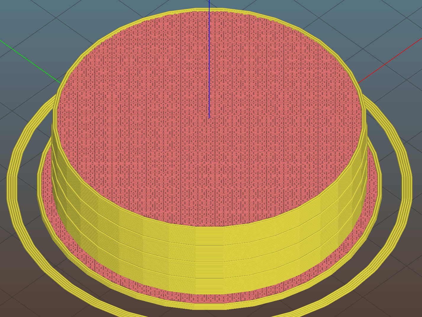
Some continuous process improvement (a.k.a OpenSCAD hackage) produced a swoopy threaded cap with thumb-and-finger grips:
Mailing Tube Screw Cap – top – Slic3r
The finger grips are what’s left after stepping a sphere out of the cap while rotating it around the middle:
Mailing Tube Cap – finger grip construction
That worked out surprisingly well, with the deep end providing enough of a vertical-ish surface to push against.
The two hex holes fit a pin wrench, because the grips twist only one way: outward. The wrench eliminates the need for a flange, as you can now adjust the cap insertion before slathering packing tape over the ends. Man, I loves me some good late binding action!
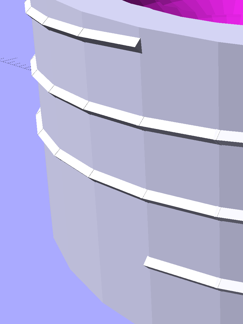
A three-start thread seemed like overkill, but was quick & easy. The “thread form” consists of square rods sunk into the cap perimeter, with one edge sticking out:
Mailing Tube Cap – thread detail
They’re 1.05 times longer than the cap perimeter facets to make their ends overlap, although they’re not tapered like the ones in the broom handle dingus, because it didn’t (seem to) make any difference to the model’s manifoldhood.
Not needing any endcaps right now, I built one for show-n-tell:
This file contains hidden or bidirectional Unicode text that may be interpreted or compiled differently than what appears below. To review, open the file in an editor that reveals hidden Unicode characters.
Learn more about bidirectional Unicode characters
Faced with a need to send documents rolled up in a tube, rather than folded flat, I sawed off a suitable length of cardboard tube from the heap, then discovered a distinct lack of end caps.
Well, once again, it’s 3D printing to the rescue:
Mailing Tube Cap – top – Slic3r
The small ribs probably don’t actually do anything, but seemed like a nice touch.
They’re somewhat less boring from the bottom:
Mailing Tube Cap – bottom – Slic3r
The fancy spider supports that big flat top and provides some crush resistance. The flat flange should collect the edge of the packing tape wrapped around the ends.
A firm shove installs them, so the size worked out perfectly:
Mailing tube end cap – installed
Add a wrap of tape to each end, affix the USPS label, and they went out with the next day’s mail, PETG hair and all.
This file contains hidden or bidirectional Unicode text that may be interpreted or compiled differently than what appears below. To review, open the file in an editor that reveals hidden Unicode characters.
Learn more about bidirectional Unicode characters
Improving the crystal tester’s (nonexistent) grounding requires a band of copper tape around the inside of the proto board holder. Rather than cut the tape lengthwise to fit the holder, a new one will be just tall enough:
Proto Board – 80×120 – revised inserts – Slic3r
While I was at it, I deleted the washer recesses, because those didn’t work out well, and fiddled the screw holes to put the inserts in from the bottom:
This file contains hidden or bidirectional Unicode text that may be interpreted or compiled differently than what appears below. To review, open the file in an editor that reveals hidden Unicode characters.
Learn more about bidirectional Unicode characters
AD8310 module bracket on proto board holder – component side
The OLED display looks a bit faded, which seems to be an interaction between matrix refresh and camera shutter: looks just fine in person!
Not much to see from the other side:
AD8310 module bracket on proto board holder – solder side
I should have included an offset to slide it a bit forward; then I could mount it on the other end with clearance for the Nano’s USB port. Maybe next time.
This file contains hidden or bidirectional Unicode text that may be interpreted or compiled differently than what appears below. To review, open the file in an editor that reveals hidden Unicode characters.
Learn more about bidirectional Unicode characters
The weather got warm enough to open the windows before pollen season started, which led to the front bathroom door slamming closed in the middle of the night when a gusty rainstorm blew through town. After far too many years, I decided this was an annoyance up with which I need no longer put.
A few minutes with OpenSCAD and Slic3r produces the shape:
Bathroom Door Retainer – Slic3r
It’s basically an extrusion of a 2D shape with a rectangular recess for the door chewed out.
An hour later, it’s in full effect:
Bathroom Door Retainer – installed
The model now sports a little ball to secure the retainer against the towel bar:
Bathroom Door Retainer – bump
Maybe someday I’ll reprint it.
That was easy …
The cast-iron pig sometimes standing guard as a doorstop in the relatively narrow doorway poses a bit of a foot hazard, so he moves into a closet during the off season. He can now remain there, snug and comfy, until a need for ballast arises.
This file contains hidden or bidirectional Unicode text that may be interpreted or compiled differently than what appears below. To review, open the file in an editor that reveals hidden Unicode characters.
Learn more about bidirectional Unicode characters
Having figured the mixing ratios, found the mixing trays, and donned my shop apron, I buttered up several iterations of the badge reel case to see how XTC-3D epoxy works on the little things around here.
In all cases, I haven’t done any sanding, buffing, or primping, mostly because I’m not that interested in the final surface finish.
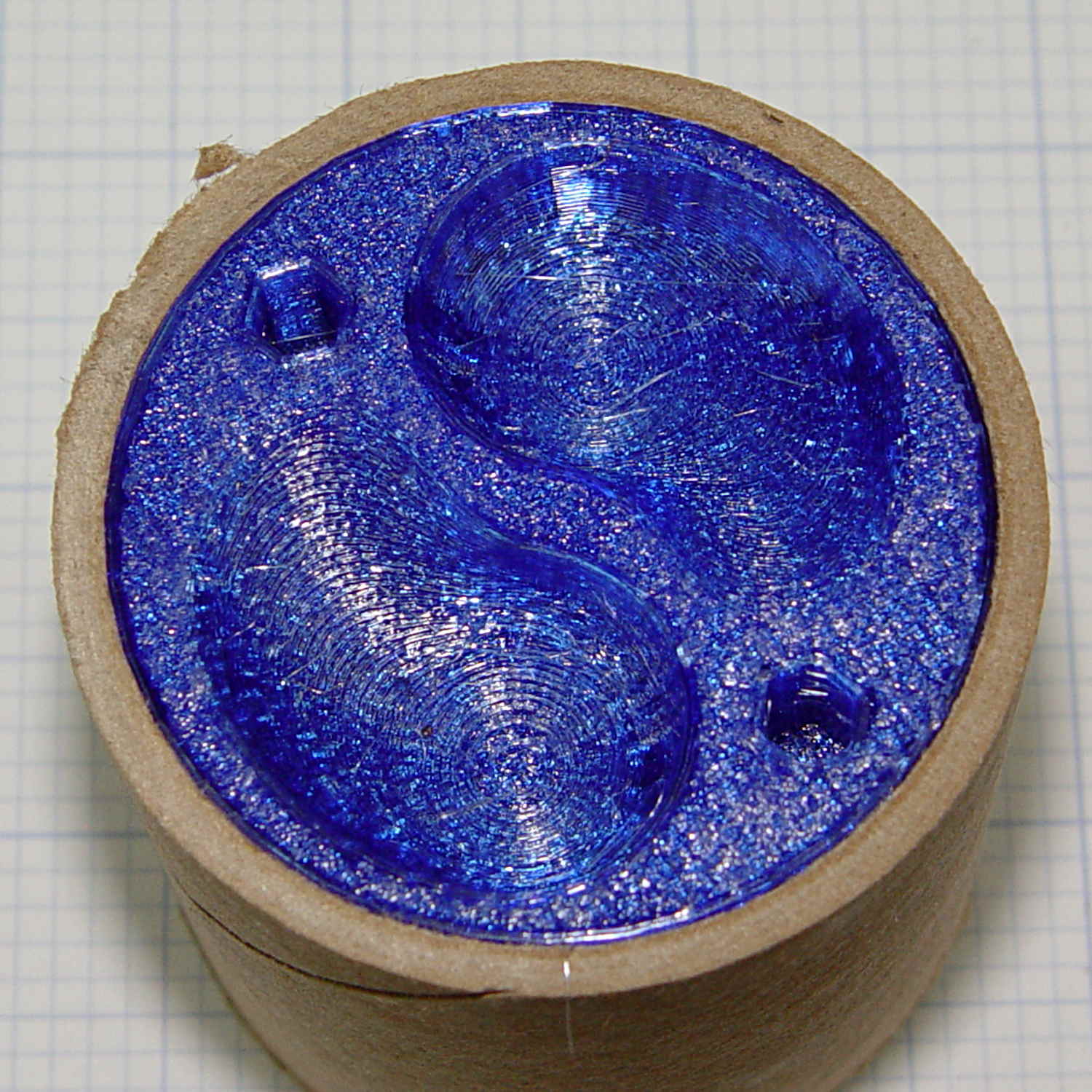
A single coat produces a glossy finish with ripples from the printed threads:
XTC-3D – Hilbert – reflective
Seen straight on, without the glare, a little speck toward the lower right corner shows that cleanliness is next to impossible around here:
XTC-3D – lines – direct
An additional coat atop a Hilbert-curve upper surface comes out somewhat smoother:
XTC-3D – Hilbert – reflective 2
Another view, with less glare, shows the pattern a bit better:
XTC-3D – Hilbert – reflective 1
With no glare, the 3D Honeycomb infill shows through the surface:
XTC-3D – Hilbert – direct
Coating the surface with epoxy definitely makes it more transparent / less translucent by filling in the air gaps.
The sides of that part have only one coat and still show typical 3D printed striations.
Three coats wipe out the striations, along with all other surface detail:
XTC-3D – Bezel – front oblique
The bolt head recesses collected enough epoxy to require reaming / milling, which certainly isn’t what you want in that situation. The bolt holes also shrank, although my usual hand-twisted drill would probably suffice to clear the epoxy.
Another view shows a glint from the smooth surface filling the upper-right recess:
XTC-3D – Bezel – front
Three coats definitely hides the 3D printed threads, although you can see some ridges and edges:
XTC-3D – heavy – oblique
The epoxy isn’t perfectly self-leveling, probably due to my (lack of) technique:
XTC-3D – heavy – reflection
Blowing out the contrast shows the surface finish:
XTC-3D – heavy – direct – boost
Those scratches come from fingernails, after the overnight curing time. The surface is hard, but not impervious to scratching, which is about what you’d expect for a clear epoxy.
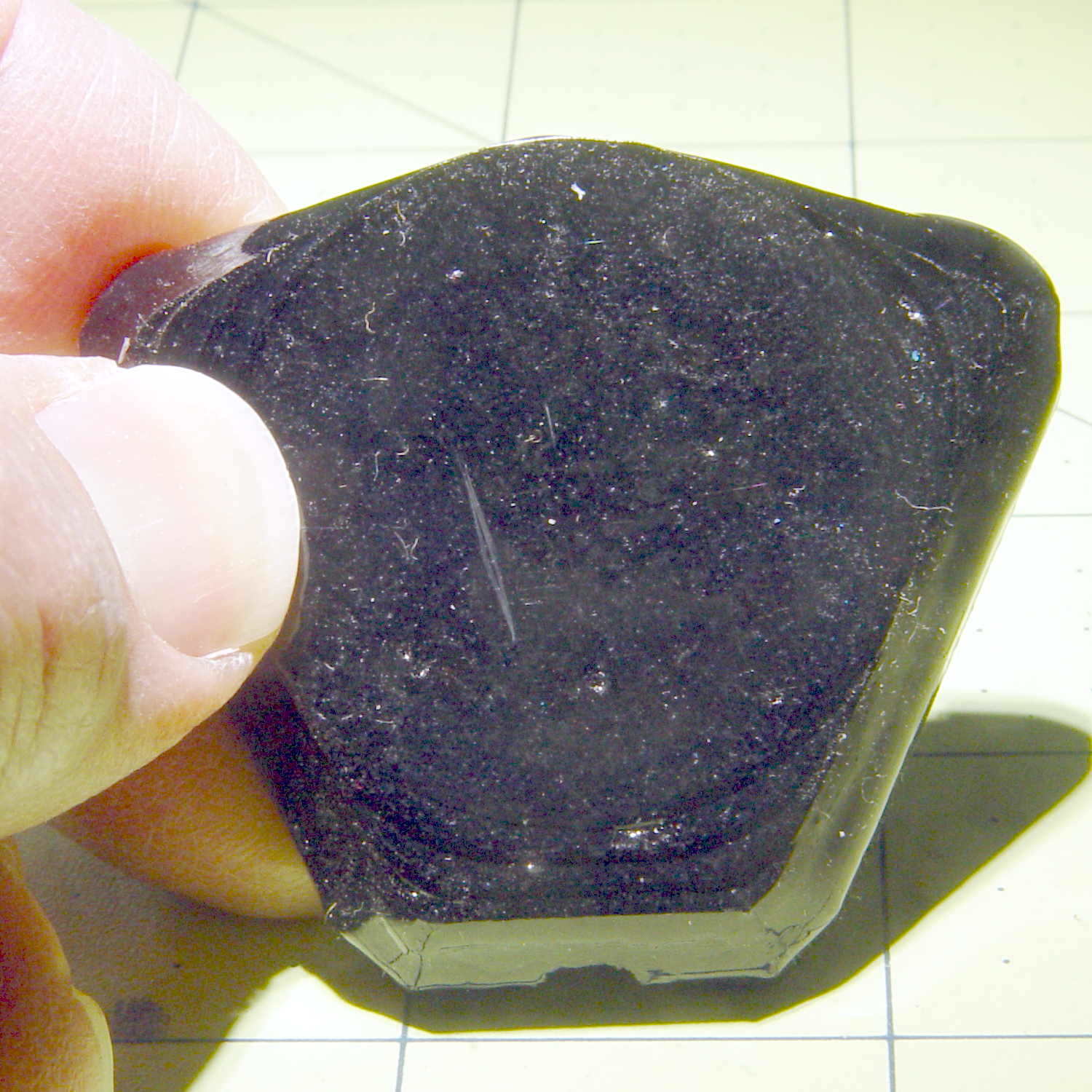
Slightly over-thinning the XTC-3D with denatured alcohol in a 0.7 : 0.3 : 0.3 by weight ratio produced a watery liquid that penetrated directly into the surface:
XTC-3D – thinned – oblique
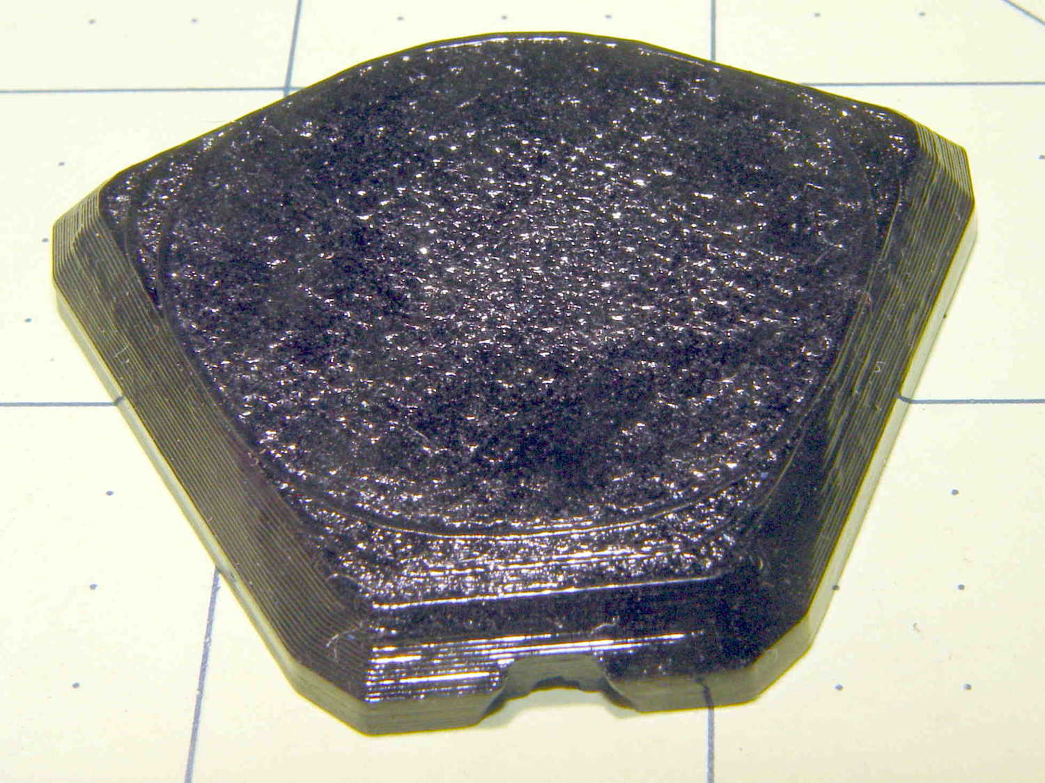
The finish depends critically on what’s below the surface and how much epoxy you apply. I tried to spread it uniformly with a foam brush, but the center came out somewhat rougher than the outer edge:
XTC-3D – thinned – oblique
The striations along the sides filled in a bit, but surely not enough to satisfy anybody who worries about such things.
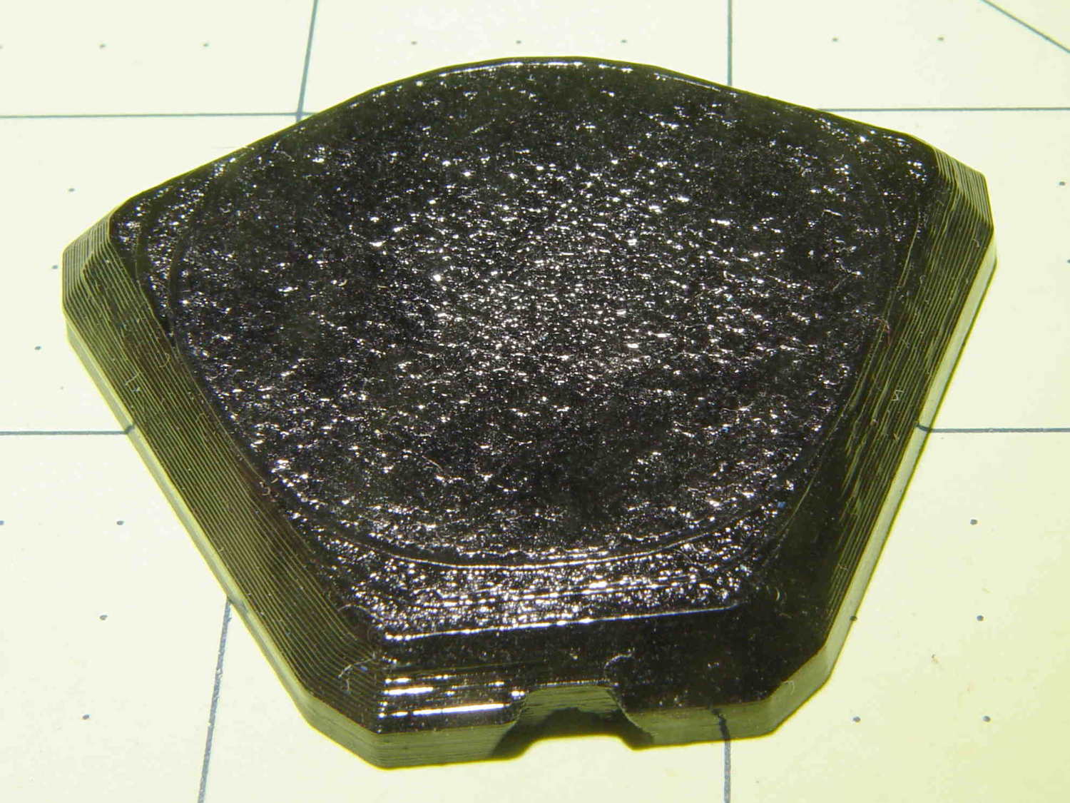
A specular reflection shows the changing surface smoothness:
XTC-3D – thinned – oblique reflective
Perhaps two coats of thinned epoxy would produce a watertight / airtight part, without changing the overall dimensions by very much. The mechanical properties depend almost entirely on the plastic-to-plastic bond, so I doubt a thin epoxy layer would improve its pressure-handling capabilities.
Few of the parts I make will benefit from an epoxy coating and I definitely don’t want to get into post-processing the parts just to improve their looks!