The Smell of Molten Projects in the Morning

Ed Nisley's Blog: Shop notes, electronics, firmware, machinery, 3D printing, laser cuttery, and curiosities. Contents: 100% human thinking, 0% AI slop.

Tag: M2

Using and tweaking a Makergear M2 3D printer

  • Sillcock Faucet Alignment Wedge: Getting the Angle Right

    Sillcock Faucet Alignment Wedge: Getting the Angle Right

    A pair of frost-free sillcock faucets arrived to replace the house’s leaky and un-repairable hose bibs. The faucet must be mounted at a 5° angle to let the water drain out when it’s closed:

    Everbilt Frost-Free Sillcock faucet - installation
    Everbilt Frost-Free Sillcock faucet – installation

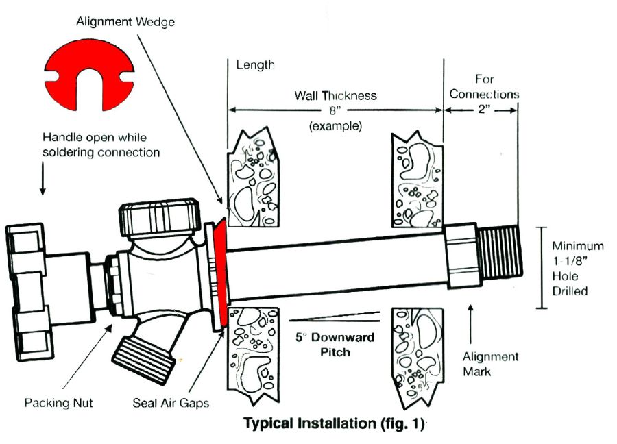
    One might expect the Alignment Wedge included with the faucet to have a 5° angle. Because I can both measure and math, it has a 1° angle.

    Well, I can fix that.

    Start by scanning the bottom (widest side) of the wedge and apply GIMP’s Select by color tool:

    Sillcock faucet alignment wedge - GIMP color selection
    Sillcock faucet alignment wedge – GIMP color selection

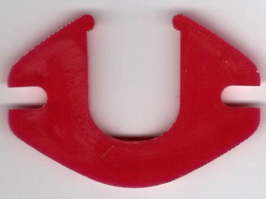
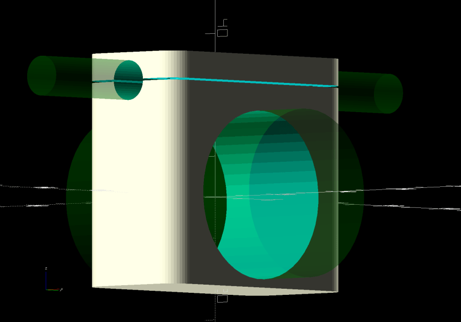
    After a little manual cleanup in Quick Mask mode, apply a 1 mm inset to ensure it snaps around the pipe, convert the selection to a path, export it as an SVG image, and import it into OpenSCAD to cut the angle:

    // Sillcock faucet alignment wedge
    // Ed Nisley KE4ZNU - May 2024
    
    MaxThick = 5.0;
    Tilt = -5.0;
    
    PlateOA = [60,40,MaxThick];   // XY = original angle plate size
    
    difference() {
      linear_extrude(height=MaxThick,convexity=5)
        offset(r=-1.0)
          import("/mnt/bulkdata/Cameras/2024/Shop Projects/Sillcock Faucets/Sillcock faucet angle washer - outline.svg",
                 center=true);
       translate([-PlateOA.x/2,-PlateOA.y/2,MaxThick])
         rotate([Tilt,0,0])
            cube(PlateOA,center=false);
    }
    

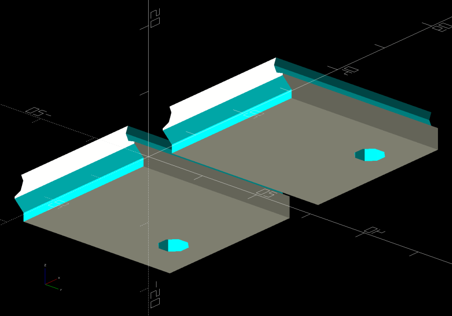
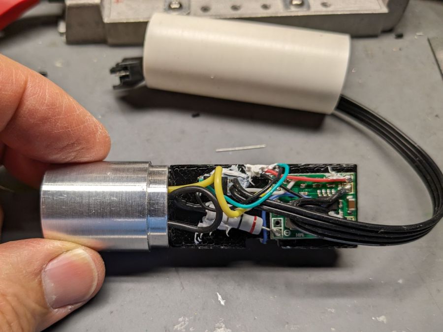
    The solid model goes into PrusaSlicer for duplication & slicing:

    Sillcock faucet alignment wedge - PrusaSlicer layout
    Sillcock faucet alignment wedge – PrusaSlicer layout

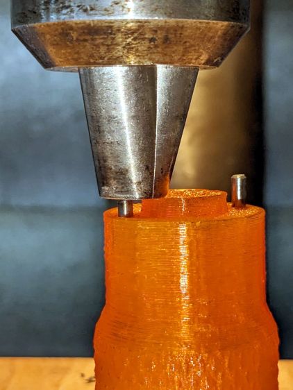
    And comes off the printer looking just about like you’d expect:

    Sillcock faucet alignment wedge - OEM vs printed
    Sillcock faucet alignment wedge – OEM vs printed

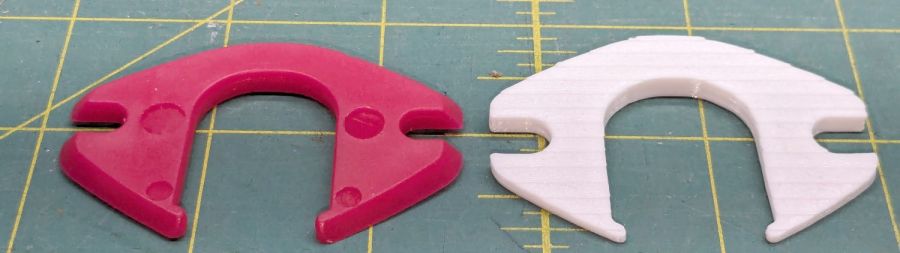
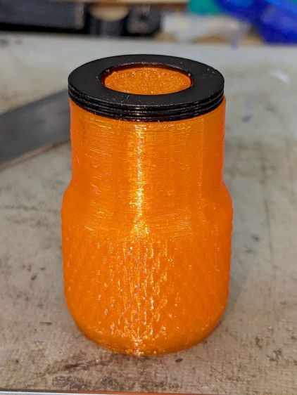
    The far side of both wedges are 5 mm tall, but you can see the difference four more degrees makes in the front.

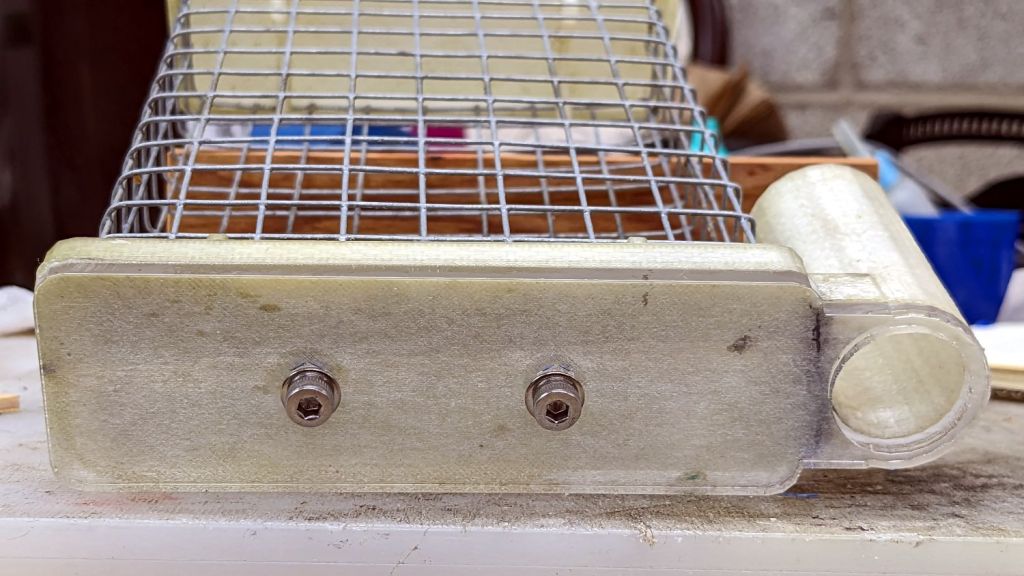
    It’s even more obvious from the edge:

    Sillcock faucet alignment wedge - on pipe
    Sillcock faucet alignment wedge – on pipe

    The wood siding where these will fit is perfectly vertical, so getting the wedge angle right isn’t really optional.

    I must drill the existing hole in the sill plate out to 1-1/8 inch to clear the pipe fittings, plus the wood around the screws holding the current bibs to the wall will surely need some buttressing, but all that’s in the nature of fine tuning.

    FWIW, this was the first 3D print after the move and I’m happy to say the M2 had no any need of adjustments.

    The WordPress AI image generator apparently ignored the post text and produced a stylin’ picture of an arched bathroom faucet over a rimless sink, which I shall leave to your imagination.

  • Under-shelf Kitchen Light Bracket

    Under-shelf Kitchen Light Bracket

    Quite a while ago I’d added another LED strip to the under-cabinet light array, because the little cutting boards & suchlike on a wire shelf blocked the light, but fastened it in place with ugly wire ties.

    Finally I found a Round Tuit on the desk for brackets mounting the strip directly to the shelf:

    Kitchen Light Bracket - shelf blocks - solid model
    Kitchen Light Bracket – shelf blocks – solid model

    Ram a pair of brass inserts in the holes, screw the strip in place, snap the brackets between the wires, and it’s much better:

    Kitchen Light Bracket - installed
    Kitchen Light Bracket – installed

    Stipulated: those wire ends look awful. Fortunately, they’re normally hidden by the cutting boards and suchlike on the shelf.

    Although it looks precarious, the rounded sides (seem to) have enough grip on the wires to hold the LED strip in place. We’ll see how well that works in practice, but the idea was to avoid anything sticking up above the wires to collide with the stuff on the shelf.

    The blocks emerge from a chunk of code glommed onto the original OpenSCAD program:

    ShelfWireDia = 3.2;
    ShelfWireOC = 1*inch;
    StrutWireDia = 6.3;
    
    ShelfBlock = [ShelfWireOC,LEDEndBlock.y,(0.8*ShelfWireDia + StrutWireDia/2)/cos(180/8)];
    echo(ShelfBlock=ShelfBlock);
    
    LEDHoleOffset = [ShelfBlock.x/2 - (6.0 + ShelfWireDia/2),6.0];  // from Y+ and X±
    LEDHoleDia = 3.0;
    
    ID = 0;
    OD = 1;
    
    M3Insert = [3.0,4.0,4.2];   // short M3 knurled insert
    
    <<< snippage >>>
    
    module ShelfBlocks(Side=1) {
    
      difference() {
        translate([0,ShelfBlock.y/2,ShelfBlock.z/2])
          cube(ShelfBlock,center=true);
       translate([Side*LEDHoleOffset.x,ShelfBlock.y - LEDHoleOffset.y,-Protrusion])
          rotate(180/8)
            PolyCyl(M3Insert[OD],M3Insert[LENGTH] + 2*ThreadThick,8);
        translate([-2*ShelfBlock.x,-StrutWireDia/4,0])
          rotate([0,90,0]) rotate(180/8)
            PolyCyl(StrutWireDia,4*ShelfBlock.x,8);
        for (i=[-1,1])
          translate([i*ShelfWireOC/2,-ShelfBlock.y,(StrutWireDia/2 + ShelfWireDia/2)/cos(180/8)])
            rotate([-90,0,0]) // rotate(180/8)
              PolyCyl(ShelfWireDia,3*ShelfBlock.y,8);
      }
    }
    
    <<< snippage >>>
    
    if (Layout == "ShelfBlocks")
      for (i=[-1,1])
        translate([i*(ShelfBlock.x/2 + 3.0),0,0])
          ShelfBlocks(i);


    Should’a done that years ago …

  • Tour Easy: DPC-18 Display Controls

    Tour Easy: DPC-18 Display Controls

    The Bafang 500C display I installed on Mary’s Tour Easy recumbent has assist level buttons along its left edge:

    Bafang display - clamp bushing
    Bafang display – clamp bushing

    This required her to take her left hand off the handlebar to fiddle with the assist level and, as it turned out, used her thumb in position causing some distress. Given that changing the assist level happens a lot as we ride, it was time for a change.

    So I replaced the 500C with a DPC-18 display like the one on my bike, with the key advantage of putting the buttons on the handgrip:

    Tour Easy Bafang Controls - DPC-18 buttons
    Tour Easy Bafang Controls – DPC-18 buttons

    She preferred a higher position for the buttons than I do, with the PTT button for the Baofeng amateur radio below the housing.

    After a few iterations, the throttle moved from the right handgrip to the right end of the handlebar crosspiece on a lengthened version of the mount I conjured for Tee’s Terry Symmetry upright bike:

    Tour Easy Bafang DPC-18 - throttle mount
    Tour Easy Bafang DPC-18 – throttle mount

    That location requires a bit of dexterity, but let us move the twist-grip shifter upward on the handgrip where it is more comfortable. She rarely uses the throttle, so we’ll try this for a while.

    The DPC-18 has an awkward portrait-mode display with an incredible amount of wasted space, with the side detriment of displacing the blue Camelbak hose. After a few iterations, we settled on a receptacle to catch the mouthpiece without requiring any fancy snaps / clips / fasteners:

    Tour Easy Bafang Controls - Camelbak nozzle catcher
    Tour Easy Bafang Controls – Camelbak nozzle catcher

    The solid model descends from the Zzipper fairing mounts on that same aluminum bar, with the bottle simply jammed into the big hole:

    Zzipper Fairing - Camelbak nozzle catcher - show layout
    Zzipper Fairing – Camelbak nozzle catcher – show layout

    There being no real forces on the holder, I omitted the aluminum load-spreading plate across the top and just epoxied four threaded brass inserts into the bottom part.

    Early reports suggest a happier thumb and no problems stashing the hose, so it’s all good.

  • Laser Cutter: Mirror Pin Wrench

    Laser Cutter: Mirror Pin Wrench

    After struggling with pin pliers again, I finally made a pin wrench for the laser cutter’s mirror retaining rings:

    Laser Mirror Pin Wrench - in use
    Laser Mirror Pin Wrench – in use

    The odd grayish tint toward the flat end of the knob comes from residual black filament in the hot end after switching to retina-burn orange PETG.

    The solid model looks about like you’d expect:

    Mirror Pin Wrench - Solid Model
    Mirror Pin Wrench – Solid Model

    The pins are snippets of 3/32 inch = 2.4 mm steel rod with ground-round ends to fit the 2.5 mm pin sockets in the retaining ring.

    They’re rammed into place with a drill press to keep them aligned with the holes:

    Laser Mirror Pin Wrench - pin insertion
    Laser Mirror Pin Wrench – pin insertion

    Pressed flush with the central boss that aligns the wrench with the ring:

    Laser Mirror Pin Wrench - pin leveling
    Laser Mirror Pin Wrench – pin leveling

    Then put the ring on the bench, set the wrench atop the ring with the pins in the sockets, and press firmly to seat the pins to the proper depth. The end results should look like this:

    Laser Mirror Pin Wrench - mirror ring test
    Laser Mirror Pin Wrench – mirror ring test

    The next time I clean the mirrors, there will be less muttering.

    The OpenSCAD source code as a GitHub Gist:

    // OMTech laser cutter mirror pin wrench
    // Ed Nisley – KE4ZNU – August 2023
    // From https://www.thingiverse.com/thing:4146258
    use <knurledFinishLib_v2_1.scad>
    /* [Hidden] */
    ThreadThick = 0.20;
    ThreadWidth = 0.40;
    HoleWindage = 0.2; // extra clearance
    Protrusion = 0.1; // make holes end cleanly
    inch = 25.4;
    //———————-
    // Dimensions
    /* [Knob] */
    PinDia = 2.4; // pin diameter
    PinOC = 20.5; // … on-center spacing
    PinDepth = 10.0; // … hole depth
    LocDia = 14.5; // central stud
    LocLength = 3.0;
    ShaftDia = 26.0; // un-knurled section diameter
    ShaftLength = 15.0; // … length
    KnurlDia = 30.0; // diameter at midline of knurl diamonds
    KnurlLen = 20.0; // … length of knurled section
    /* [Hidden] */
    KnurlDPNom = 32; // Nominal diametral pitch = (# diamonds) / (OD inches)
    DiamondDepth = 0.5; // … depth of diamonds
    DiamondAspect = 2; // length to width ratio
    KnurlID = KnurlDia – DiamondDepth; // dia at bottom of knurl
    NumDiamonds = ceil(KnurlDPNom * KnurlID / inch);
    echo(str("Num diamonds: ",NumDiamonds));
    NumSides = 4*NumDiamonds; // 4 facets per diamond
    KnurlDP = NumDiamonds / (KnurlID / inch); // actual DP
    echo(str("DP Nom: ",KnurlDPNom," actual: ",KnurlDP));
    DiamondWidth = (KnurlID * PI) / NumDiamonds;
    DiamondLenNom = DiamondAspect * DiamondWidth; // nominal diamond length
    DiamondLength = KnurlLen / round(KnurlLen/DiamondLenNom); // … actual
    TaperLength = 0.75*DiamondLength;
    KnobOAL = ShaftLength + KnurlLen + 2*TaperLength;
    //———————-
    // Useful routines
    module PolyCyl(Dia,Height,ForceSides=0) { // based on nophead's polyholes
    Sides = (ForceSides != 0) ? ForceSides : (ceil(Dia) + 2);
    FixDia = Dia / cos(180/Sides);
    cylinder(r=(FixDia + HoleWindage)/2,
    h=Height,
    $fn=Sides);
    }
    //- Build it
    difference() {
    union() {
    render(convexity=10)
    translate([0,0,TaperLength])
    knurl(k_cyl_hg=KnurlLen,
    k_cyl_od=KnurlDia,
    knurl_wd=DiamondWidth,
    knurl_hg=DiamondLength,
    knurl_dp=DiamondDepth,
    e_smooth=DiamondLength/2);
    color("Orange")
    cylinder(r1=ShaftDia/2,
    r2=(KnurlDia – DiamondDepth)/2,
    h=(TaperLength + Protrusion),
    $fn=NumSides);
    color("Orange")
    translate([0,0,(TaperLength + KnurlLen – Protrusion)])
    cylinder(r2=ShaftDia/2,
    r1=(KnurlDia – DiamondDepth)/2,
    h=(TaperLength + Protrusion),
    $fn=NumSides);
    color("Moccasin")
    translate([0,0,(2*TaperLength + KnurlLen – Protrusion)])
    cylinder(r=ShaftDia/2,h=(ShaftLength + Protrusion),$fn=NumSides);
    color("Brown")
    translate([0,0,KnobOAL – Protrusion])
    cylinder(r=LocDia/2,h=(LocLength + Protrusion),$fn=NumSides);
    }
    for (i=[-1,1])
    translate([i*PinOC/2,0,KnobOAL – PinDepth])
    rotate(180/6)
    PolyCyl(PinDia,PinDepth + Protrusion,6);
    }

    It descends from a long line of similar things dating back to the OG Sherline Speed Wrenches.

  • Tour Easy Running Lights: Anodizing Sun Fade

    Tour Easy Running Lights: Anodizing Sun Fade

    After six years, the anodizing on the Anker LC40 flashlights I repurposed as daytime running lights shows some radiation damage:

    Tour Easy Running Lights fading - mount top view
    Tour Easy Running Lights fading – mount top view

    The bottom side looks pristine:

    Tour Easy Running Lights fading - mount bottom view
    Tour Easy Running Lights fading – mount bottom view

    It turns out they were clamped in slightly different positions on our two bikes:

    Tour Easy Running Lights fading - top view
    Tour Easy Running Lights fading – top view

    The side view shows a gentle color transition:

    Tour Easy Running Lights fading - bottom view
    Tour Easy Running Lights fading – bottom view

    Apparently I had swapped the caps from the two lights when I noticed the fading after only the first year.

  • Onion Maggot Fly Sticky Trap Repair

    Onion Maggot Fly Sticky Trap Repair

    One of the sticky traps absorbed a mighty blow during the season and its ski-pole mount snapped off. Rather then rebuild the whole thing, I decided to just epoxy the pieces together and stick a reinforcing plate on the bottom.

    I added a pair of screw holes to the OpenSCAD model and produced a projection of the bottom layer:

    if (Layout == "Projection") {
        projection(cut=true) {
            Attachment();
            Cap();
        }
    }
    

    Which looked like this:

    Sticky Sheet Cage - projection
    Sticky Sheet Cage – projection

    Cutting that shape from an adhesive sheet looks the same:

    Onion Maggot Fly Trap - adhesive sheet
    Onion Maggot Fly Trap – adhesive sheet

    The somewhat raggedy large hole seems to come from OpenSCAD’s somewhat low-res SVG outline conversion.

    Fill the broken part with epoxy:

    Onion Maggot Fly Trap - epoxy ready
    Onion Maggot Fly Trap – epoxy ready

    Clamp it together on a plate to keep the bottom aligned:

    Onion Maggot Fly Trap - clamping
    Onion Maggot Fly Trap – clamping

    Cut an acrylic baseplate:

    Onion Maggot Fly Trap - acrylic cut
    Onion Maggot Fly Trap – acrylic cut

    Apply adhesive sheet to acrylic, stick it on the bottom of the cage, add a pair of stainless steel screws, and declare victory:

    Onion Maggot Fly Trap - bottom view
    Onion Maggot Fly Trap – bottom view

    We’ll see how long that lasts out in the garden next year …

  • Tour Easy Running Lights: Mechanics

    Tour Easy Running Lights: Mechanics

    The running lights have the same general structure as before and fit into the same front and rear holders:

    Tour Easy Running Light - rear installed
    Tour Easy Running Light – rear installed

    I made the recess slightly deeper to provide a bit more protection to the lens:

    Tour Easy Running Light - front installed
    Tour Easy Running Light – front installed

    The lenses have a 10° beam angle, so a few more millimeters of sidewall doesn’t intercept much light.

    The layout doodle grew a few more notes:

    Tour Easy running light - housing dimensions
    Tour Easy running light – housing dimensions

    I had the good idea of boring the tube, knurling the rod, then epoxying the two together before cutting the rod:

    Tour Easy Running Light - heatsink curing
    Tour Easy Running Light – heatsink curing

    Which let the lathe hold them in perfect alignment during curing:

    Tour Easy Running Light - heatsink plug alignment
    Tour Easy Running Light – heatsink plug alignment

    The rod fits through the lathe spindle and I intended to use it as an arbor while turning the tube exterior, then cut the finished heatsink off flush.

    Which really good idea lasted until the next morning, when I looked at the setup and immediately cut the rod flush with the tube. Because reasons, perhaps excess blood in my caffeine stream.

    So I had to finish the heatsink on hard mode right up against the chuck:

    Tour Easy Running Light - turning heatsink rebate
    Tour Easy Running Light – turning heatsink rebate

    Flipping it around and gripping that little rebate to skim the OD down to 25 mm seemed fraught with peril, so I stabilized the open end with a chuck and plenty of oil; the live center was just too big around for the job.

    Dang, I hate it when I screw up a nice plan.

    Then drill various holes on the Sherline and epoxy the circuit support plate:

    Tour Easy Running Light - circuit plate curing
    Tour Easy Running Light – circuit plate curing

    After boring the PVC pipe to 23 mm ID, I made a pair of Delrin fixtures to simplify turning the exterior to 25 mm before parting it off:

    Tour Easy Running Light - turning body OD
    Tour Easy Running Light – turning body OD

    The PVC is so thin the Arduino’s LEDs shine right through:

    Tour Easy Running Light - installed top view
    Tour Easy Running Light – installed top view

    The radioactive green endcap is ordinary laser-cut fluorescent edge-lit acrylic with sunlight through the garage door on the left. I used red acrylic for the taillight to encourage their separate identities.

    The knockoff Arduino Nano fits on one side of the support plate:

    Tour Easy Running Light - Arduino view
    Tour Easy Running Light – Arduino view

    And the current regulator on the other:

    Tour Easy Running Light - current regulator
    Tour Easy Running Light – current regulator

    Because these run from a dedicated 6.3 V step-down regulator, rather than the Bafang controller’s headlight output, the 2.0 Ω sense resistor sets the LED current to 0.8 V / 2.0 Ω = 400 mA, which is pretty close to the LED 1 W spec.

    The white blob at the end of the two ribbon cable wires is the optoisolator pulling down a pin when the LIGHT signal is active, telling the firmware to stop the normal blink pattern and just turn the LED on all the time. This will come in handy if I ever do any night riding.

    The LED is epoxied to the aluminum shell (with metal-filled JB Weld) and the whole affair never gets more than comfortably warm even with the LED running constantly.

    I think they came out All Good™, despite various blunders along the way.