This worked out surprisingly well:

Not knowing what to expect, I peeled the protective plastic off the styrene PETG sheet before cutting the perimeter, thereby dooming myself to about five minutes of polishing with Novus 2 to remove the condensed vaopor and another five minutes restoring the shine with Novus 1. Next time, I’ll know better.
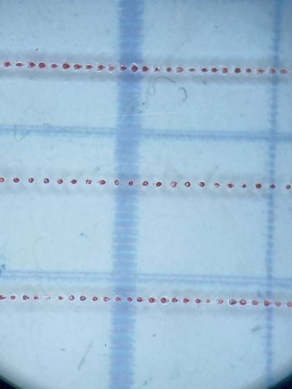
Eyeballometrically, the hairline is a lovely fine line, but it’s really a series of craters on 0.25 mm centers filled with red Pro Sharpie marker and wiped off with denatured alcohol:
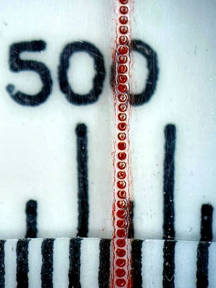
That’s dot mode: 2 ms pulses at 20% power (about 12 W) with a line speed of 100 mm/s and 0.25 mm dot spacing. The craters look to be 0.15 mm in diameter, with a 0.15 mm blast radius merging into a line along the sides. The view is looking through the undamaged side of the cursor, so you’re seeing the craters from their tips.
I cut the cursor and engraved / etched the hairline in one operation, by just laying a rectangle on the honeycomb and having my way with it:
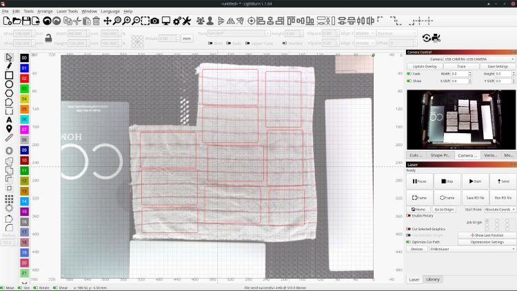
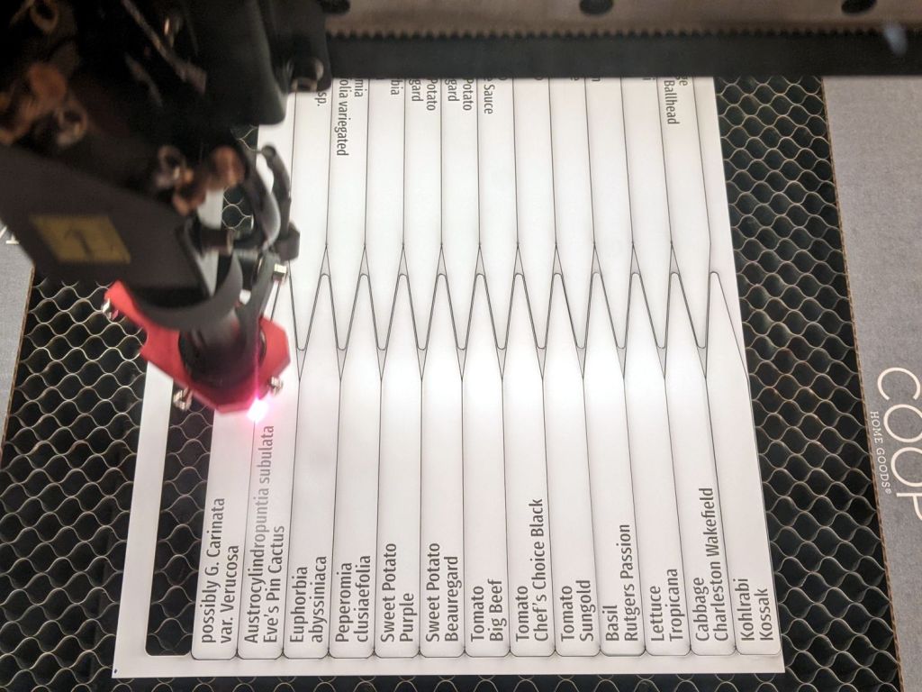
For a more systematic test I aligned a cursor engraving fixture I built for the Sherline atop the laser’s honeycomb platform and wedged it into place with eccentric stops, then dropped a cursor milled on the Sherline in place:
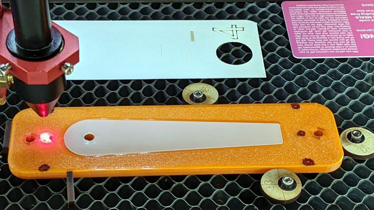
The six pips (small printed holes with ugly black outlines) intended for the Sherline’s laser aligner make this feasible, although the accuracy of the OMTech’s laser pointer requires precisely setting the focal point atop the fixture.
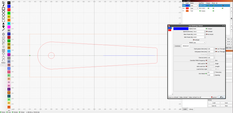
The corners of LightBurn’s tooling layer (the enclosing rectangle) match the corner pip positions, so framing the pattern should light up those four holes. Putting the Job Origin (small green square) at the center-left point lets me tweak the machine’s origin to drop the alignment laser into that pip.
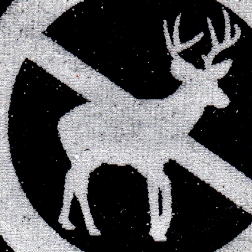
AFAICT, burning a cute puppy picture pretty close to the middle of a slate coaster makes everybody else deliriously happy.
Setting up the cut layer parameters:
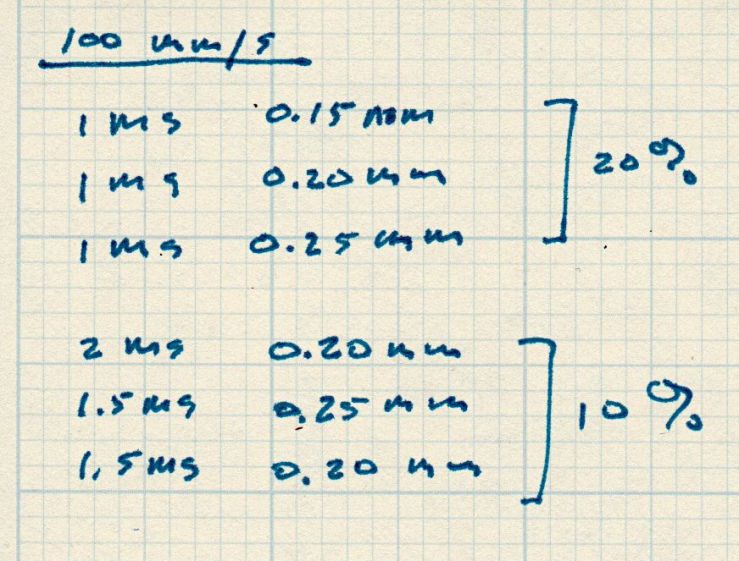
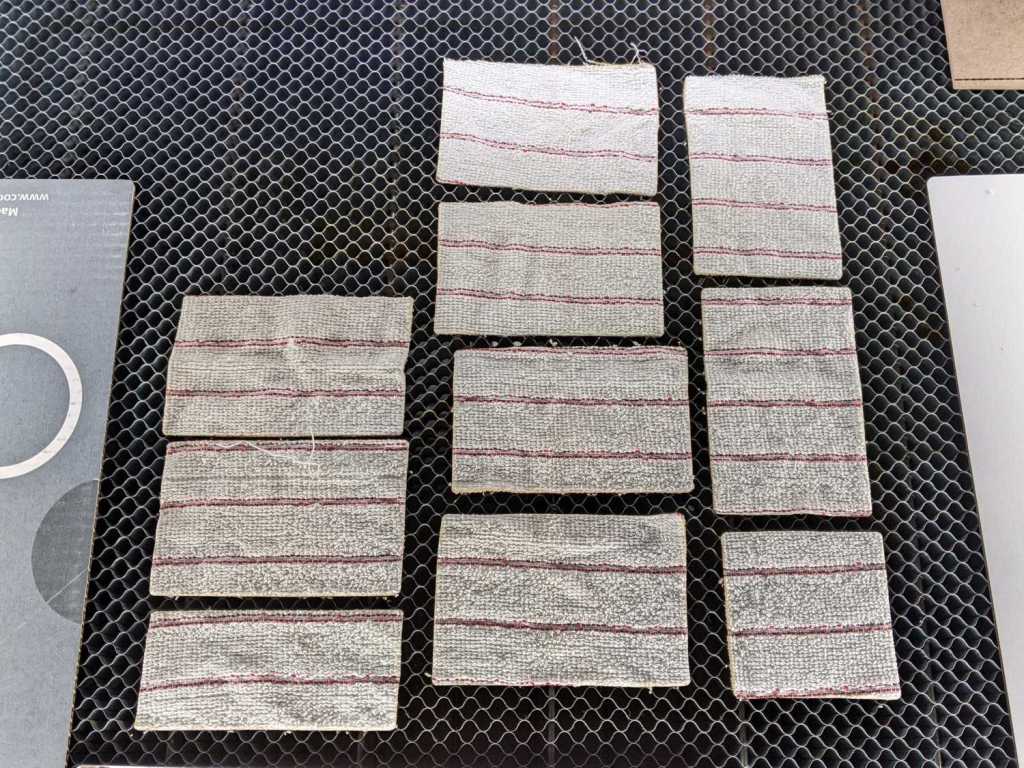
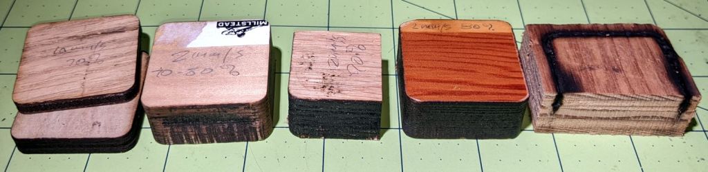
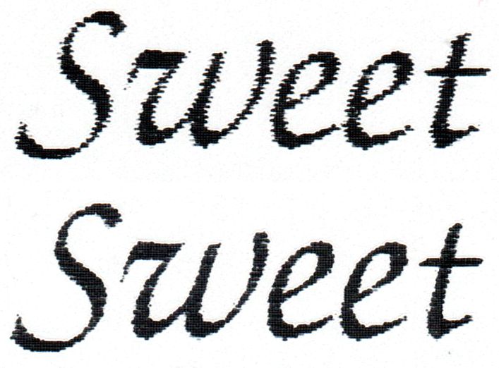
Burning through the protective film, peeling it off, filling with Sharpie, and wiping with alcohol produces interesting results against a 0.1 inch = 2.54 mm grid:
The angled top and bottom lines are the edges of the cursor, positioned with the craters on the top surface.
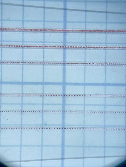
The bottom three lines at 10% power consist of distinct 0.10 mm craters incapable of holding much ink:
The top three lines at 20% power have 0.15 mm craters and look better:
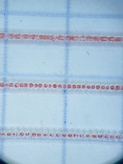
The top line was a complete surprise: it seems a 20% duty cycle does not turn off completely between 1 ms dots spaced at 0.15 mm. I expected a row of slightly overlapping dots, which is obviously not what happens.
Punching the dots through the protective film eliminated the polishing operation, although I have yet to cut the perimeter with the film in place.
More experimentation is in order, but it looks like I can finally engrave good-looking and perfectly aligned hairlines on nicely cut cursors without all those tedious manual machining operations.
[Update: dot mode can produce a continuous trench that looks even better! ]