Ed Nisley's Blog: Shop notes, electronics, firmware, machinery, 3D printing, laser cuttery, and curiosities. Contents: 100% human thinking, 0% AI slop.
First you mix the epoxy, then you blend in the dye, then you dispense it into the thing you are making. If you’re using many colors, this is obviously not the right way to go about it:
The bar magnet holds the backplate against a bench block to keep it at right angles to the base while the adhesive cures. The base is three layers of MDF with no, small, and large holes fitting the cups. I expect many epoxy spills; scrap MDF reduces deep emotional bonding to the result.
The LightBurn project has the sign outline as a tool layer to simplify aligning the victims with the laser path, plus one layer defining the cuts for the three plates. I exported it as an SVG image with the same information as colored vectors for use in whatever laser control program you might use.
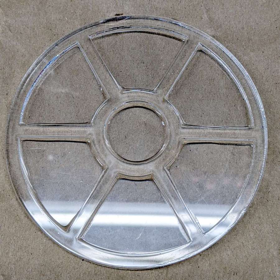
I eased a thin bead of clear epoxy along the frame sash, using less than I thought necessary, and aligned it atop the base plate:
Acrylic Coaster – frame epoxy
The excess epoxy formed fillets along the petals, a little oozed out the perimeter, and even less smeared on the top surface. The scrap acrylic didn’t have a surface mask, but that’s definitely a Good Idea for the next attempt.
Two drops of transparent red tinted the remainder of the epoxy well enough:
Acrylic Coaster – first color pour
The clear epoxy was still liquid (which is why the red epoxy was still pourable!), but the red tint stayed atop the fillet around the spot.
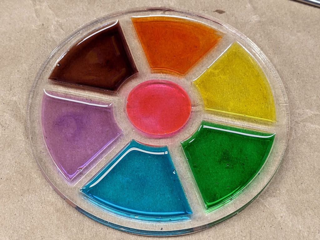
The next day:
Acrylic Coaster – epoxy coloring
Obviously, coloring epoxy for a single coaster makes absolutely no sense whatsoever, but ya gotta start somewhere.
You (well, I) can suck most of the inevitable bubbles out of the epoxy back into the dispensing pipette, but those last few bubbles will remain forever. Popping bubbles by waving a propane torch flame over the surface seems better-suited to tabletop-scale projects not involving an acrylic frame.
The epoxy puddles are about 1 mm deep inside the 2.5 mm thick frame, so (if this were a real coaster) the sashes between the petals would support the chilled mug and the petals would collect all the condensation.
Thicker epoxy would have more saturated colors and a white base plate might be in order.
With the risk of squishing excess glue through the kerf:
Chipboard coaster – excess glue
That’s the same coaster as in the first picture, carefully arranged with light reflecting off the flat glue surface. In real life, the nearly transparent glue doesn’t look nearly so awful, but smoothing much less glue than seems necessary across the bottom disk suffices.
This file contains hidden or bidirectional Unicode text that may be interpreted or compiled differently than what appears below. To review, open the file in an editor that reveals hidden Unicode characters.
Learn more about bidirectional Unicode characters
This file contains hidden or bidirectional Unicode text that may be interpreted or compiled differently than what appears below. To review, open the file in an editor that reveals hidden Unicode characters.
Learn more about bidirectional Unicode characters
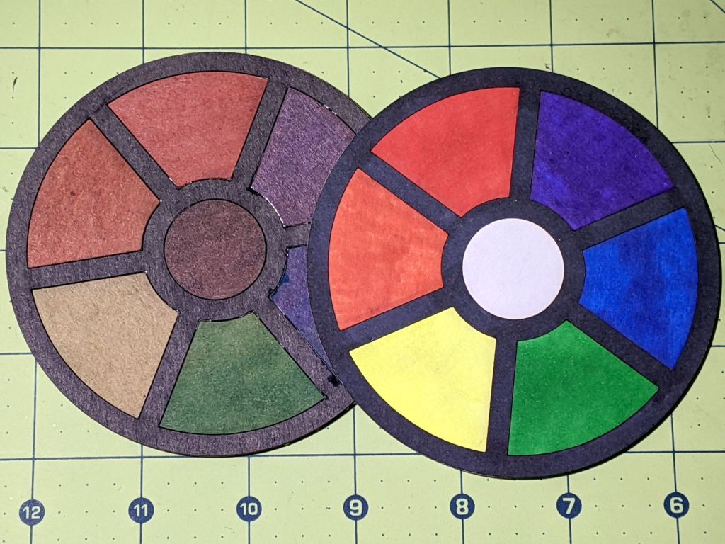
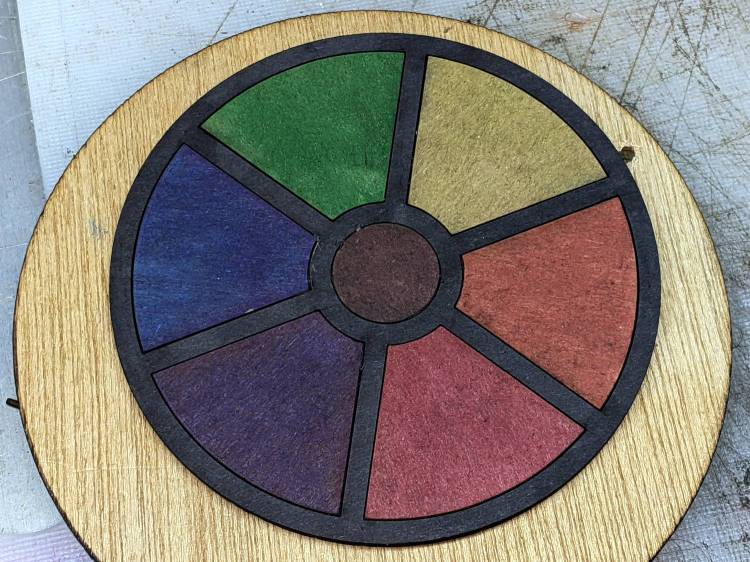
Before trying to make decorative coasters from colorful acrylic, I figured a few practice sessions in chipboard would be in order:
Chipboard coasters
They’re colored with wide tip Sharpies of various ages and, as the yellow and uncolored sections show, chipboard never gets very bright. On the other paw, chipboard is also known as “beer mat”, so at least I have the right general idea.
The patterns come from a GCMC program producing SVG figures for LightBurn to apply kerf compensation:
Chipboard coasters – cut and color
It’s obviously too late to have me color within the lines.
The overall frame in the upper left and the base plate in the upper right get the kerf compensation, which (for chipboard) turns out to be +0.15 mm outward (thus making the holes smaller and the diameter larger). If I were doing marquetry, I’d want to arrange each piece on a separate wood veneer sheet with proper grain orientation and similar fussiness, but that’s not the point right now.
Without compensation, the pieces have a drop-in fit with an obvious gap:
Coaster – chipboard – no kerf comp
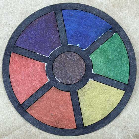
Adding a mere 0.15 mm on each side produces a very snug fit:
Coaster – chipboard – frame 0.15 out
In fact, the pieces go in from the back and require hammering gentle tapping to persuade all the corners into place.
Protip: putting a dark color on the frame and around the edges conceals many flaws.
Increasing the compensation to +0.20 mm means the pieces no longer fit and, when eventually battered into the frame, the surface becomes a concave-upward dish.
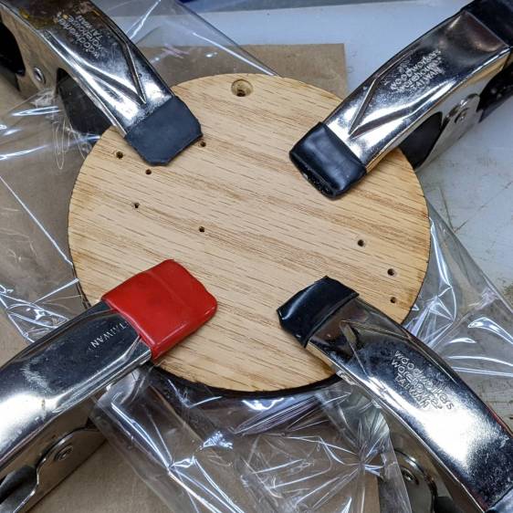
With the (colored) pieces in the frame, I covered the base plate with a thin layer of good old Elmer’s Yellow Wood Glue, dropped the top over it with some attention to good alignment on all sides, and clamped the assembly between two planks for a while. Obviously, you’d want to make more than one at a time, but they’re rather labor intensive.
The GCMC program produces the patterns from the coaster’s dimensions:
Outer diameter
Number of leaves around the center
Center spot diameter
Sash width (it’s really a muntin, but quilters say sash)
Leaf aspect ratio (max width / overall length)
Due to the relentless symmetry, finding the points describing half a leaf and half the sector between two leaves suffices to generate the entire coaster by various rotations around the center. The code performs no error checking whatsoever, so some dimensions emit a hard crash rather than a coaster.
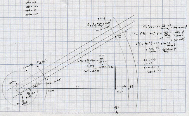
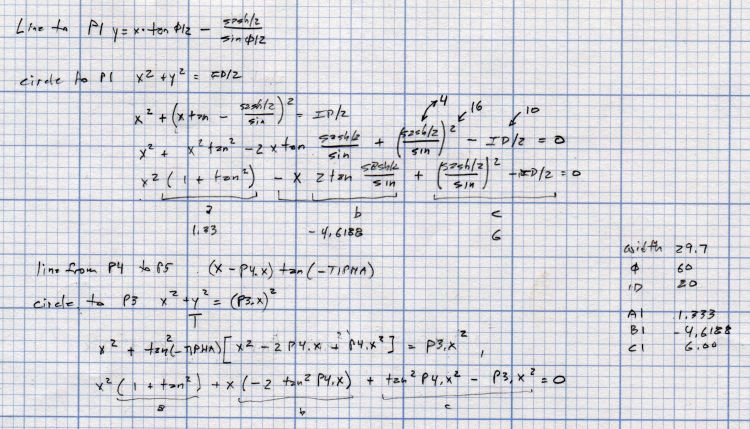
A geometry doodle with some incorrect values:
Coaster Geometry doodle
Poinr P1 (where the leaf snugs against the circular sash around the center spot) sits at the intersection of a line and a circle, so the code solves a quadratic equation with grisly coefficients:
  a = 1 + pow(tan(LeafStemHA),2);
  b = -2 * tan(LeafStemHA) * (Sash/2) / cos(LeafStemHA);
  c = pow((Sash/2) / cos(LeafStemHA),2) - pow(LeafID/2,2);
  xp = (-b + sqrt(pow(b,2) - 4*a*c))/(2*a);
  xn = (-b - sqrt(pow(b,2) - 4*a*c))/(2*a);
  y = xp*tan(LeafStemHA) - (Sash/2) / cos(LeafStemHA);
  P1 = [xp,y];
Given the geometry, the “plus” root is always the one to use.
A doodle working out that intersection, as well as for P5 out at the widest part of the leaf, carrying some errors from the geometry doodle:
Coaster Geometry equations
Both of those doodles have errors; the GCMC source code remains the final arbiter of coaster correctness.
This file contains hidden or bidirectional Unicode text that may be interpreted or compiled differently than what appears below. To review, open the file in an editor that reveals hidden Unicode characters.
Learn more about bidirectional Unicode characters
This file contains hidden or bidirectional Unicode text that may be interpreted or compiled differently than what appears below. To review, open the file in an editor that reveals hidden Unicode characters.
Learn more about bidirectional Unicode characters
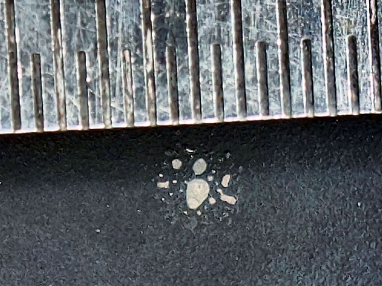
The 0.5 mm scale suggests the damage came from a defocused 2 mm beam or the hot central part of a larger beam, but I obviously wasn’t paying enough attention at the time.
The rest of the surface seems undamaged, so this may have been one of those inadvertent long-duration pulses or several shorter shots in one spot.
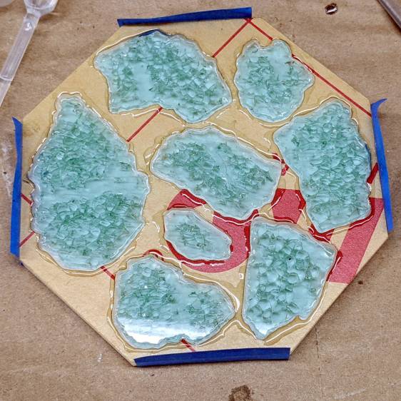
So, back to the Basement Shop, where a laser-cut and -engraved layout guide helps arrange and carry some suitable fragments:
Glass Coaster – Layout tray
As before, scan the bottom of the fragments and wrap selections around them:
Coaster Layout – selected fragments
Apply the usual operations to get a suitable mask:
Coaster Layout – fragment masks
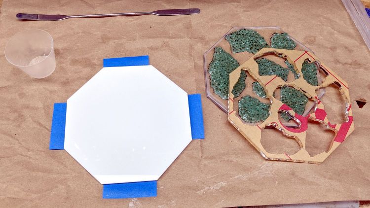
Fire the laser to cut the chipboard test template holding the fragments, then a white octagonal acrylic base plate and a transparent acrylic layer surrounding the fragments, and:
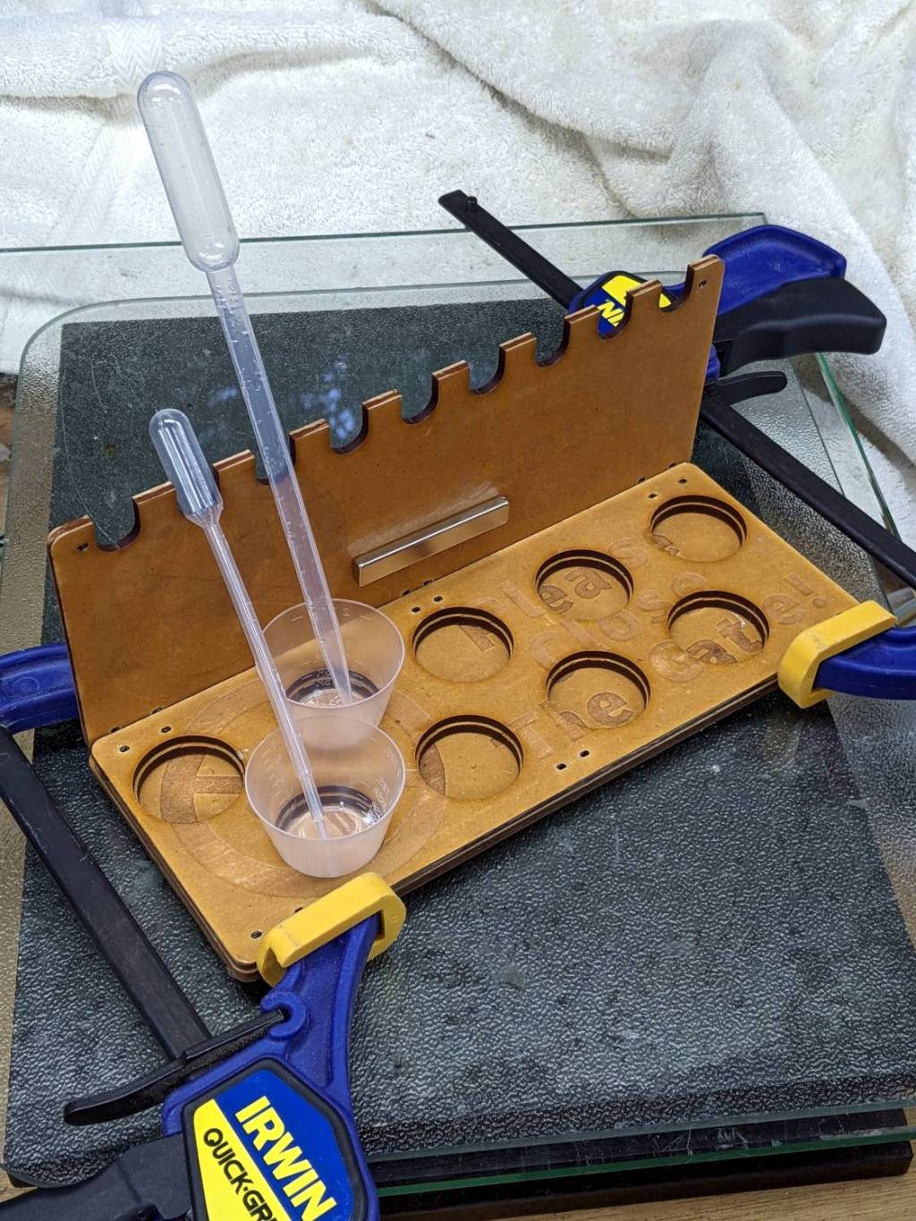
Glass Coaster – base epoxy setup
Mix up some pourable epoxy, smooth it over the base plate, squish the transparent layer atop it, use the tape (sticky side up) to hold the two layers in alignment, and gently insert the fragments:
Glass Coaster – fragment epoxy
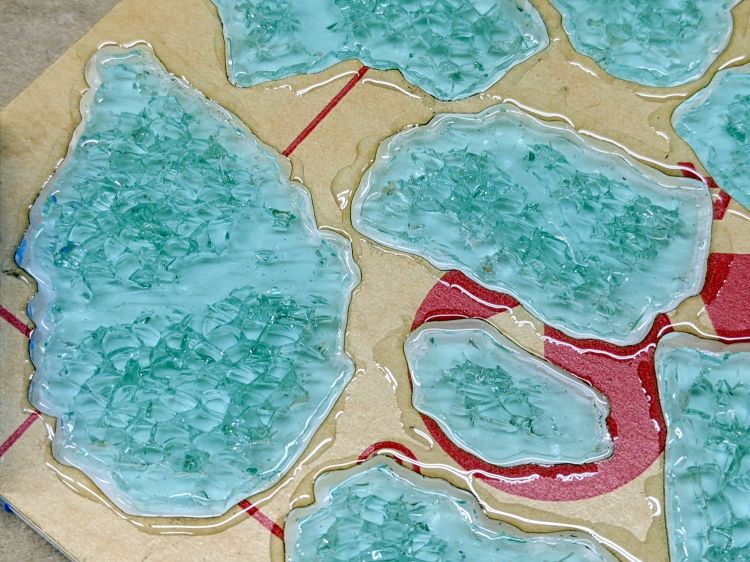
I eased some epoxy around the perimeter of each fragment with a pipette in an attempt to reduce the glass-sliver hazard:
Glass Coaster – fragment epoxy detail
Yes, that’s on top of the protective paper, because then I can whisk the paper off to reveal the pristine surface around each fragment:
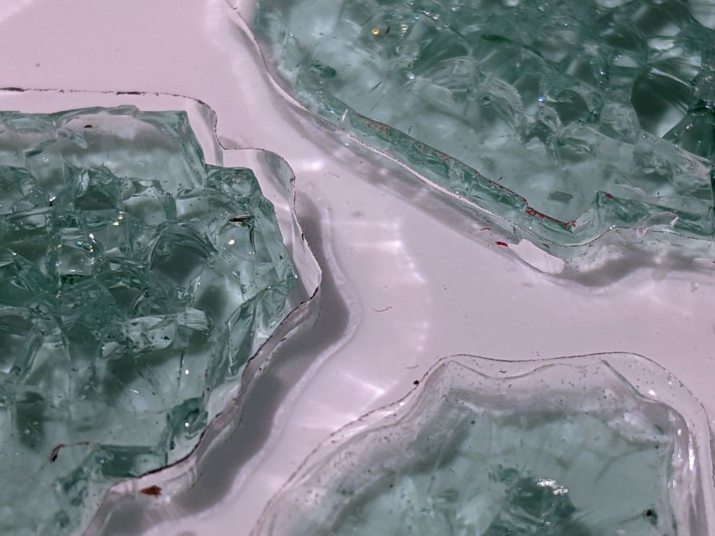
Glass Coaster – fracture filling
As with the smaller coaster, the epoxy penetrates the fractures and reduces the shattered appearance. Mary suggests tinted epoxy would produce an interesting effect and I’ll try that the next time around.
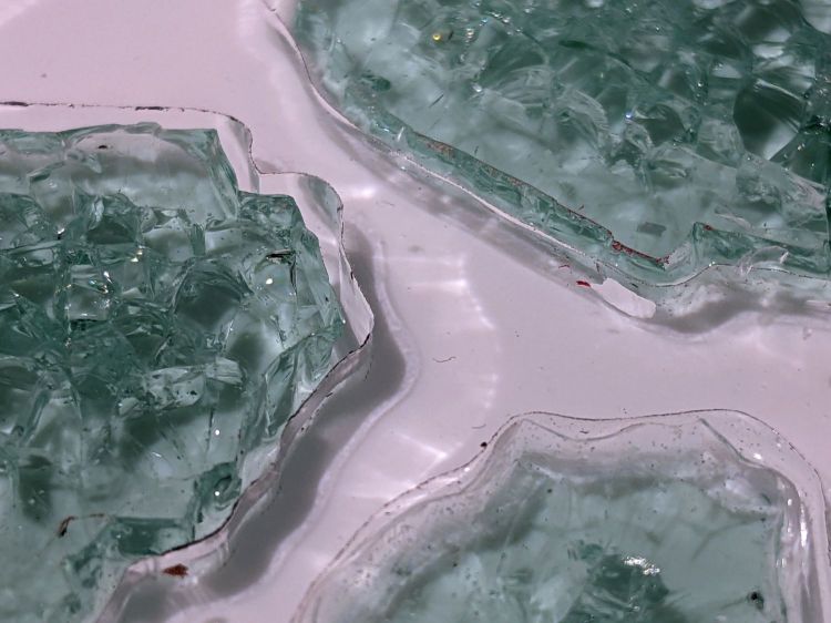
Seen through the edge of the coaster, the uneven surface of the epoxy fill around the fragments shows up clearly:
Glass Coaster – fragment edge profile
The top of the glass stands half a millimeter above the transparent acrylic. I knew that would happen and wanted to see how the bottom of the mug interacted with the epoxy-coated sides:
Glass Coaster – first test
As it turned out, the epoxy coating wasn’t quite good enough to prevent tiny slivers from chipping off and, in the cold light of day, the pale-green-ish tinted glass didn’t stand out well against the white background.
So I taped up the perimeter, leveled the base, mixed up another batch of epoxy, added two drops of opaque black dye, and poured just enough to level the surface with the glass:
Glass Coaster – black epoxy pour
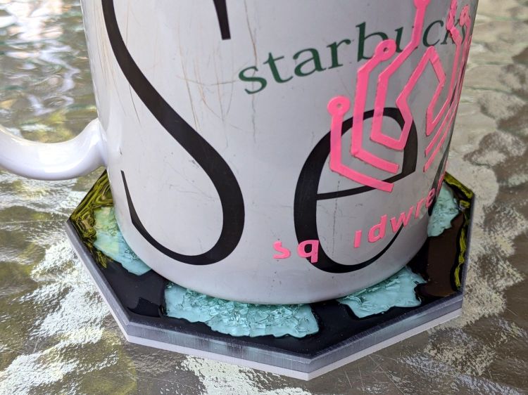
Introducing the meniscus to Mr Belt Sander put a bevel around the edge and finished it off well enough:
Glass Coaster – second test
The Squidwrench logo looks a bit battered after three and a half years of trips through the dishwasher, although I didn’t expect it to last nearly this long.
There’s still a slight upward tilt around the perimeter, but it meets my simple requirements and the fragments definitely look better in black. The white base sets off the fragments, but a clear plate takes advantage of their transparency; a mirror sheet might be even more interesting.
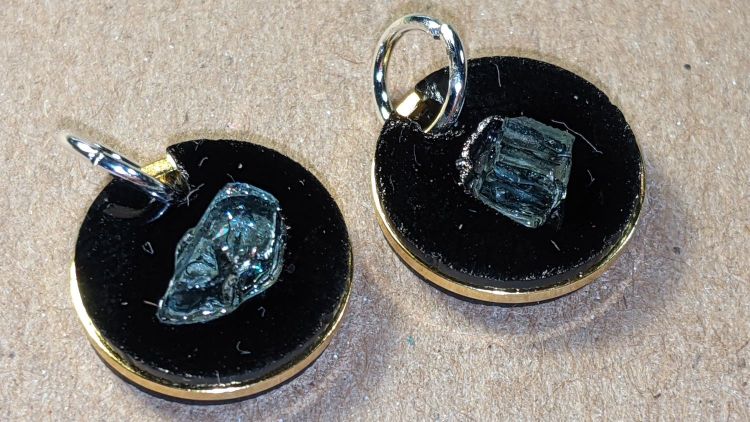
If you’re a particularly sharp person, these may accentuate your wardrobe:
Earrings – 12mm – finished
They’re fragments of smashed tempered glass, epoxied into laser-cut disks, with a ring providing some structural support. Although it’s hard to tell from the photos, the fragments sit flush with one side of the disk, which is likely the side you want closest to your carotid artery:
Earrings – 12mm – finished
Each chunk consists of a few smaller cuboids, so you get internal reflections from the minute air gaps between them. They’re not diamonds, but they’re surprisingly glittery in the proper light. Bonus: you can see right through!
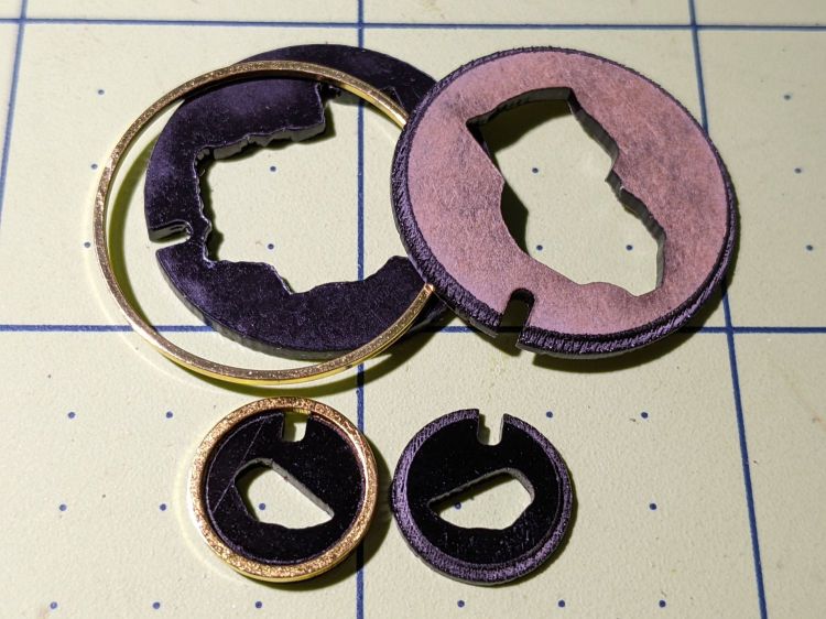
The “gold” band around the disk is a beading ring held in a notch engraved around both disks:
Earrings – rings
The smaller ring is 12 mm OD, the larger is 25 mm, with 16 mm (the descriptions says 15, but ya get what ya get) and 20 mm available for other glass fragment sizes.
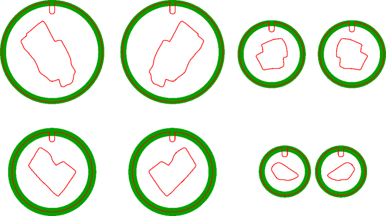
The engraved recess (green) is slightly larger than the OD to allow the perimeter cut to proceed through a thinner section:
Earring templates – 25 20 16 12 mm
Cross-hatch engraving puts a steep edge all around the recess, so the ring fits with just a little slack and turns freely around the disks.
You will, of course, have different glass fragments requiring different shapes, but the outlines came from the same process I used to make the palette organizing the fragments:
Smashed glass palette – fresh cut
You (well, I) can just import that layout, copy the outline of the chunk to be used, then delete the rest. Mirror the outline so the engraved sides of the disks fit together around the chunk, position symmetrically in the template halves, and fire the laser.
Affixing the fresh-cut disk and its glass chunk to a strip of Kapton tape (sticky side up) holds them in proper alignment and prevents the epoxy from leaking out the bottom:
Earrings – 12mm – taped
With everything lined up, run a small bead of epoxy around the chunk, squish the top disk in place, and line up the notches. When the epoxy cures, peel the earring off the tape and slide a jump ring into the notch.
As a finishing touch, you’d add a suitable ear hook or stud, but I think it’s fair to assume anything from Amazon would consist of the finest arsenic-plated plutonium and be completely unsuitable for skin contact. Neither of us have any piercings, so I cannot provide enticing action photos.
The 25 mm versions failed because I made the outlines such a snug fit around the chunks they didn’t quite fit:
Earrings – 25mm – failed
Protip: do not attempt to coerce two rigid bodies into alignment by applying firm pressure, particularly when one of them is already-broken glass.
The small earrings weigh 0.7 g each and a 25 mm one (well, the parts for a large one) comes in a bit over 3 g, plus whatever hardware goes in / on / around your ear.
This was (obviously) an exercise in small-scale laser machining, rather than a venture into haute couture. In the highly unlikely event you can’t live without a pair of custom-designed high-impact earrings, I’ll shut up and take your money … let me know if you want little or big. Black is the new black; I do have other colors, but who are you kidding?


