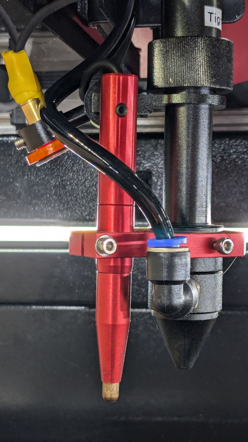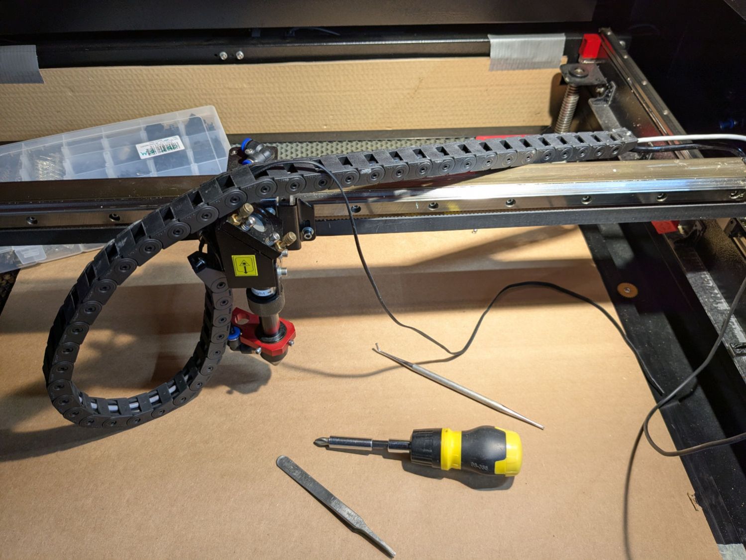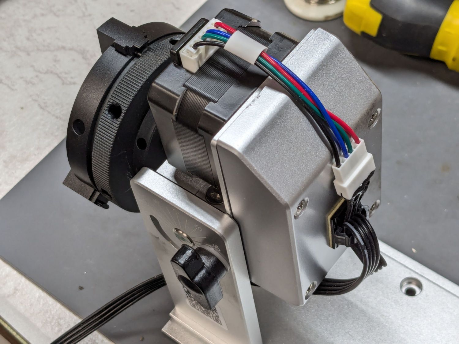
The focus “pen” = switch on the OMTech laser stuck out far below the nozzle:
The nozzle is 18.5 (-ish) mm above the surface with the laser beam focused to a tight spot. The brass (-ish) tip of the pen flew about 5 mm above the material, requiring considerable attention to the placement of magnets, clamps, and similar accoutrements around the material on the platform.
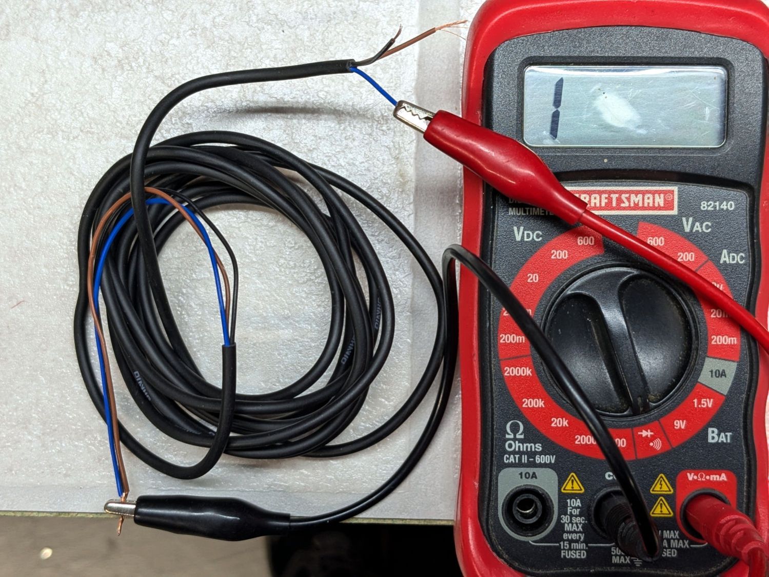
Having dismantled the pen while replacing its wiring, this seemed like a good time to figure out how to get more clearance under its tip.
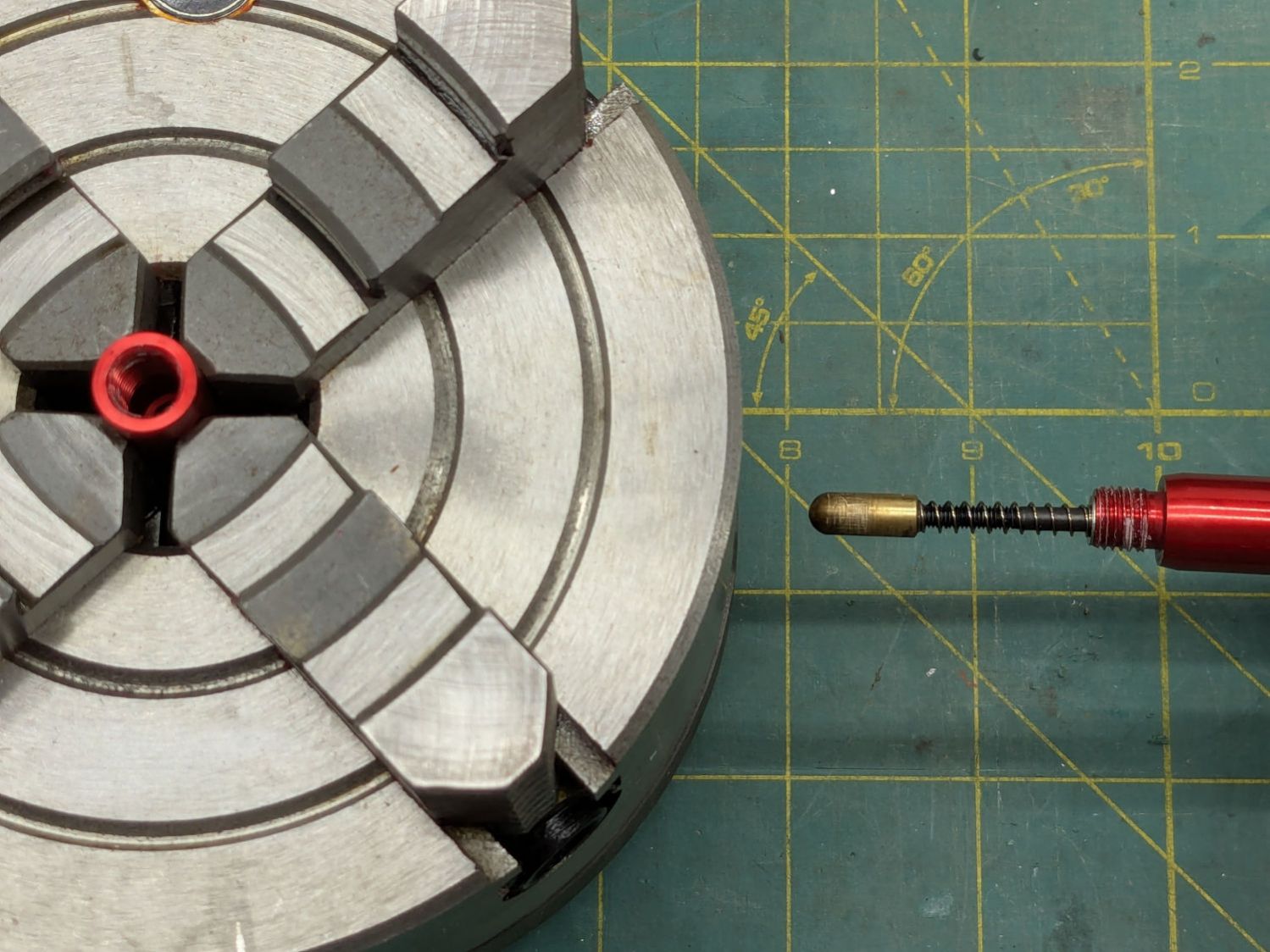
Removing the pen nose shows the tip on its 3 mm screw inside the spring pushing the tip downward:
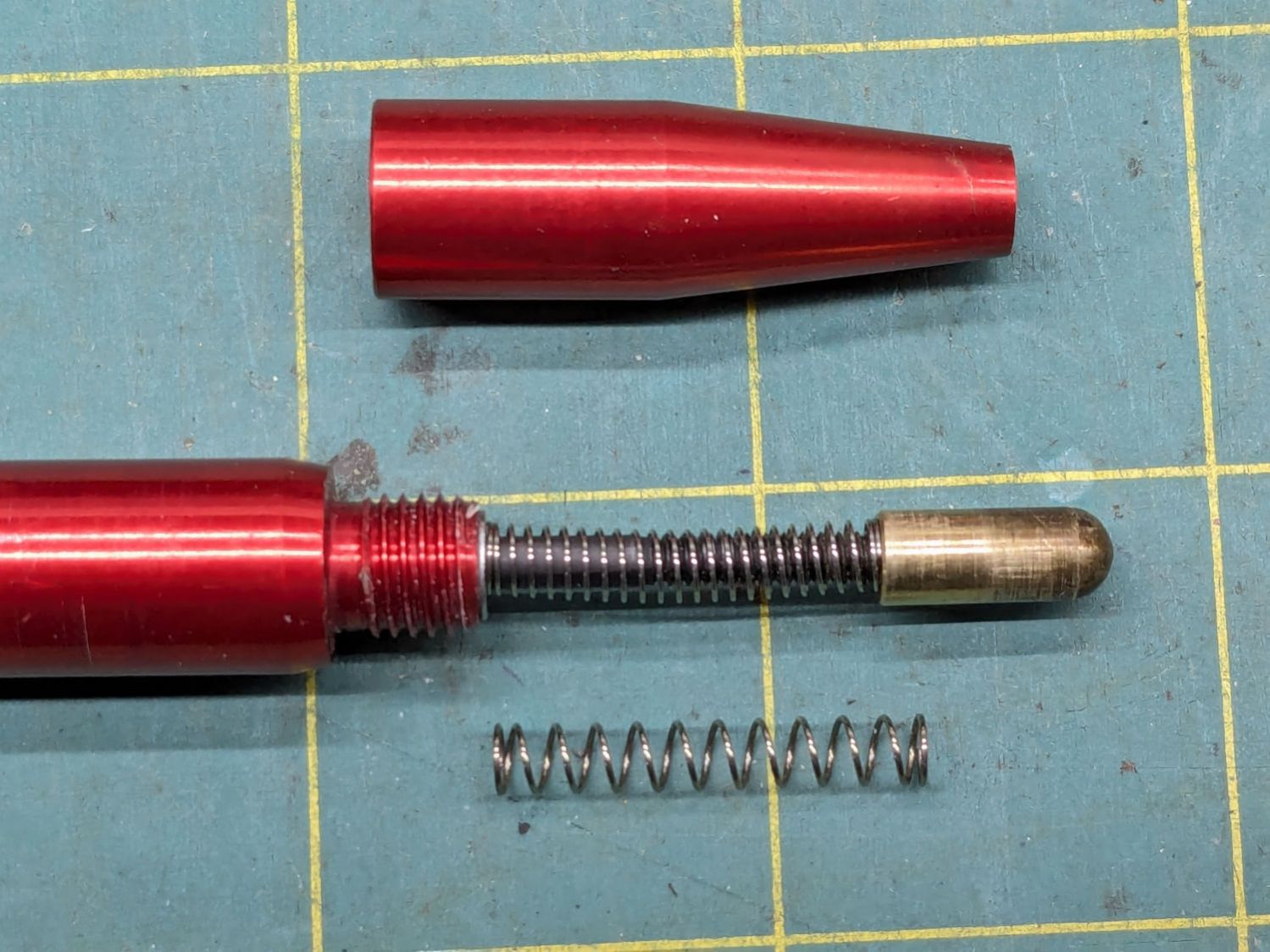
I replaced the original spring (on the bottom) with a softer spring, mostly because the tip exerted what seemed like entirely too much force on the material. That makes no difference for acrylic & plywood, but anything squishier required deploying the focus gauge after I remembered the problem.
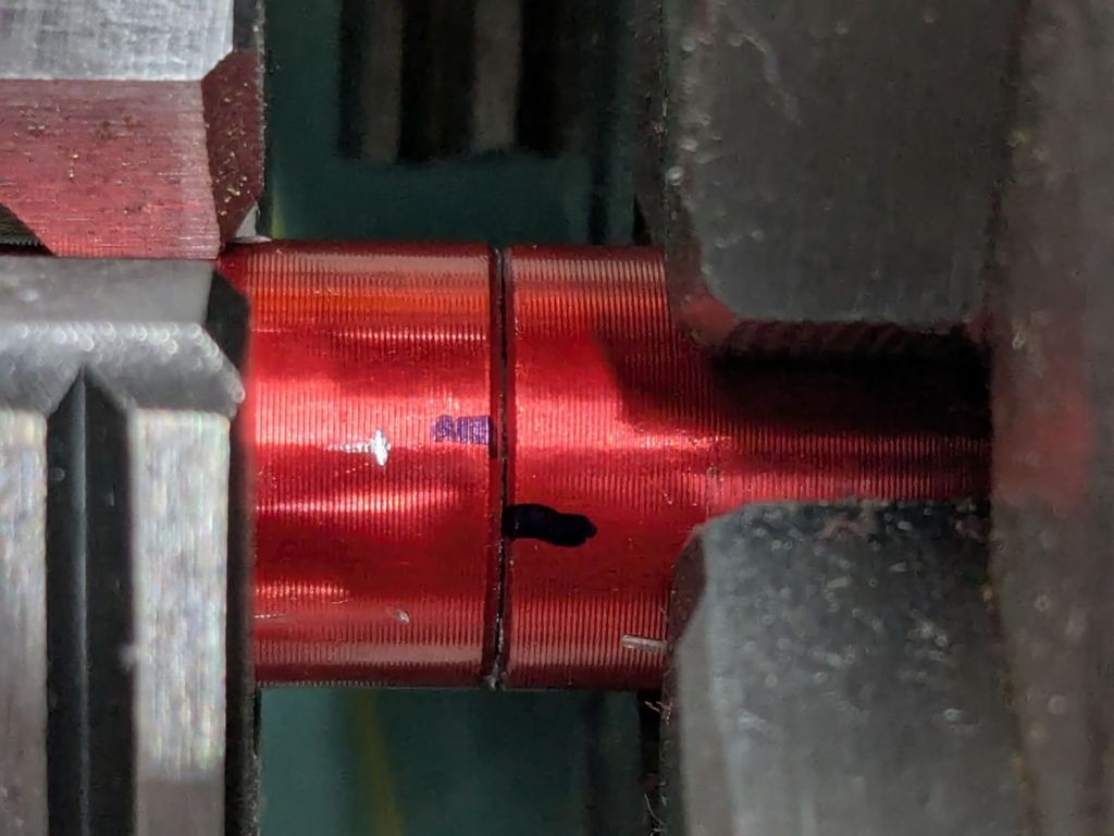
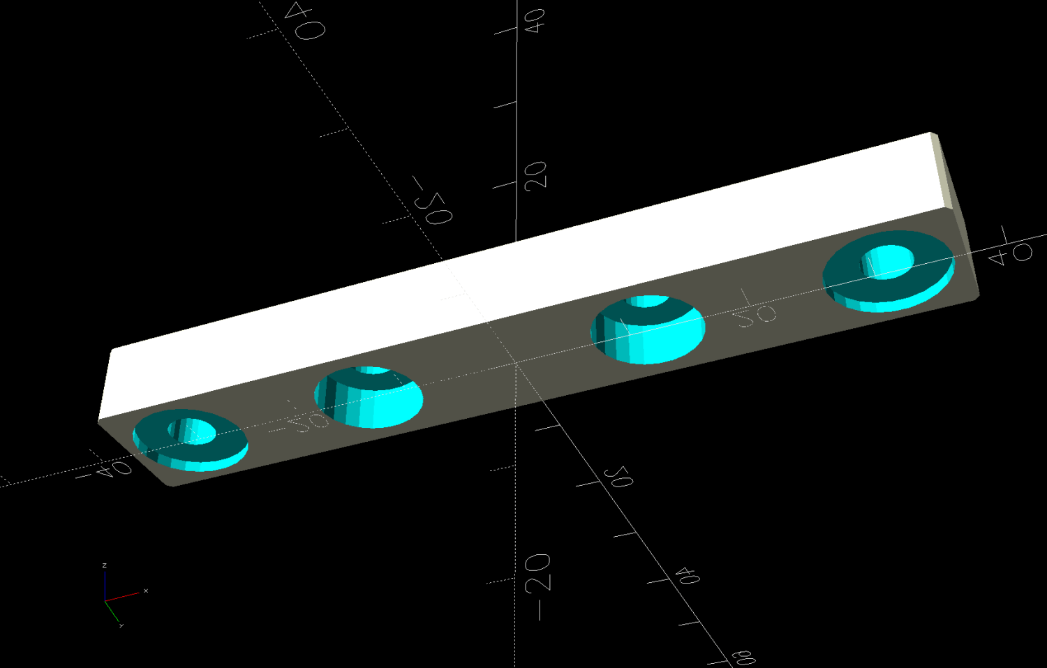
The other end of the screw is impossible to photograph in situ, but the tapered head seats in a recess leaving several millimeters of air below the proximity sensor. I made a little steel slug to reduce the pretravel by filling that gap:

The spigot on the slug (turned from 7/32 inch steel rod) aligns it with the screw head, with high-viscosity cyanoacrylate adhesive holding it in place:
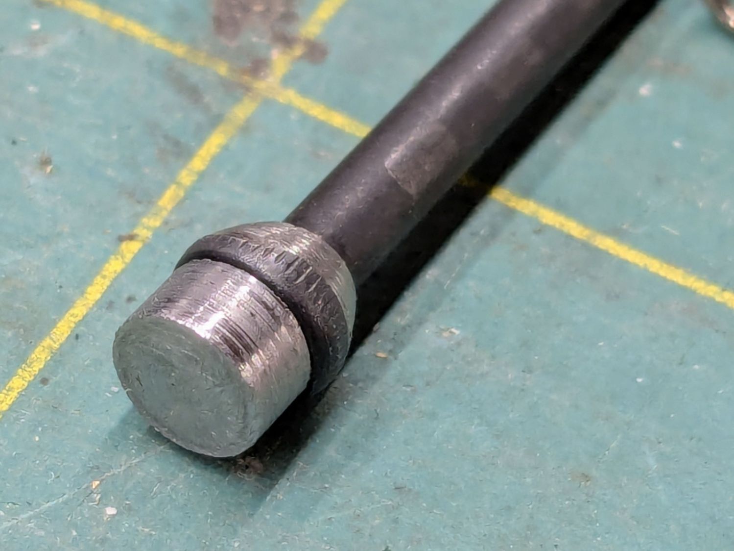
The surface finish of my slug matches their tapering, so I figure it’s about right.
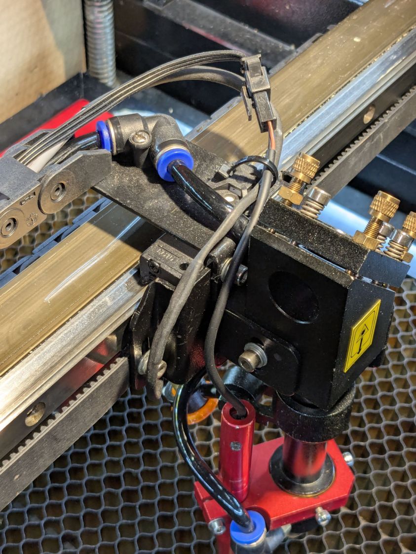
A setscrew near the top of the pen clamps the proximity sensor with a few millimeters of adjustment:

The slug reduces the pretravel to nearly zero with the sensor at the bottom of its range.
The brass tip had been twisted onto the screw as far as it would go, so I cut a few millimeters off the screw to put the tip closer to the pen nose:
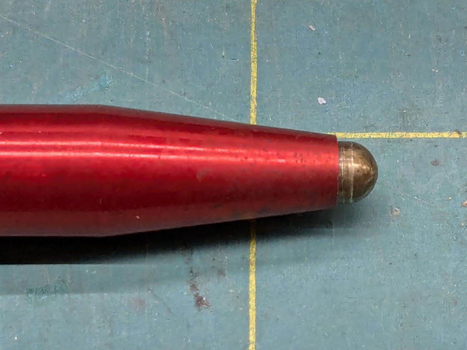
Even with reduced pretravel, the tip nearly vanished into the pen body before tripping the sensor, so I unscrewed it two turns = 1.4 mm.
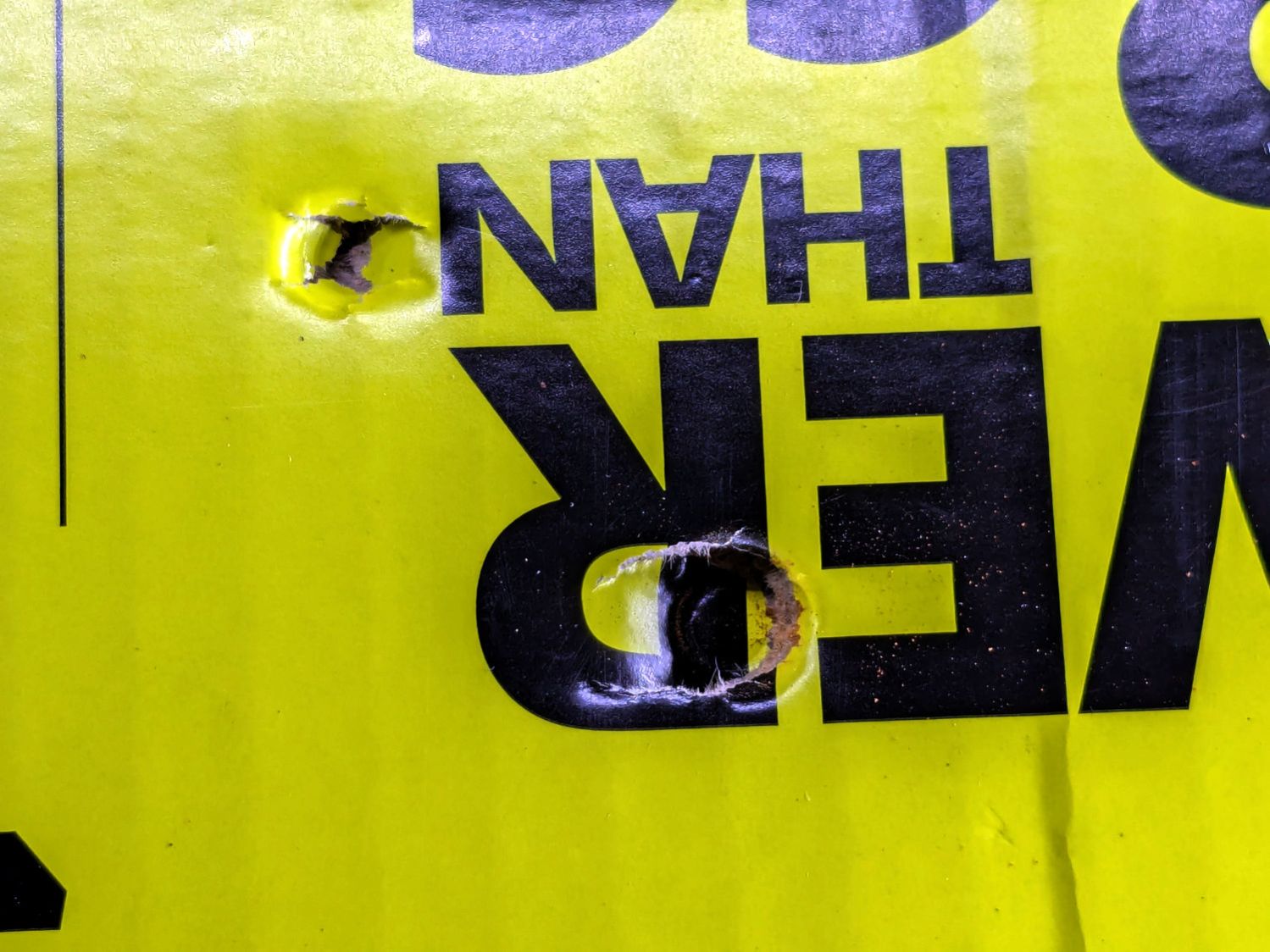
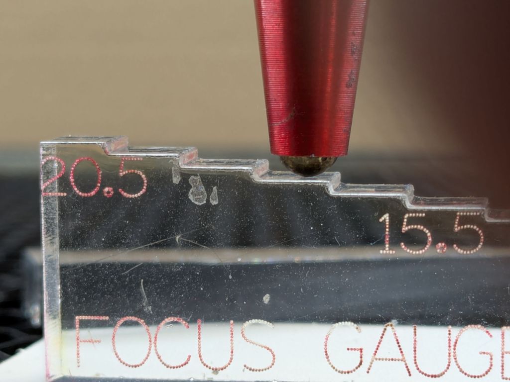
With the pen back in the machine and plugged in, measure the switch travel with a step gauge:

Protip: Measure the as-cut height of those steps, then either shim the bottom of the gauge with tape of a suitable thickness or add that much to the layout and cut another set.
With a good step gauge in hand:
- Slide it underneath to just touch the tip
- Note the measurement =
A - Slide it further until the switch trips (red LED on)
- Note the measurement =
B
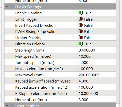
Figure B-A, round up to the next millimeter, then set that value as the Home Offset for whatever axis moves the platform. My tweaked pen had 2.5 mm of travel, so I used 3.0 mm:
Adjust the pen position to put the tip more than the Home Offset below the nozzle (I picked 5 mm) to ensure the switch will trip before the nozzle contacts the platform, then do an Autofocus.
Measure the distance from the nozzle to the platform (mine was 5.5 mm), subtract that from 18.5 mm (the known focused distance for my laser head, as above), and set that as the Focus Distance:
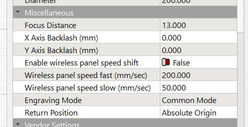
Another Autofocus should then put the nozzle exactly 18.5 mm (or whatever your machine needs) off the platform / material.
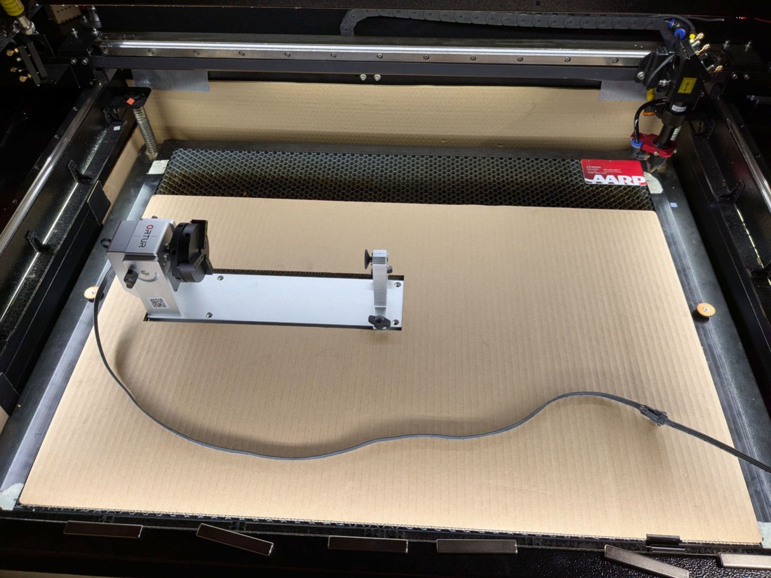
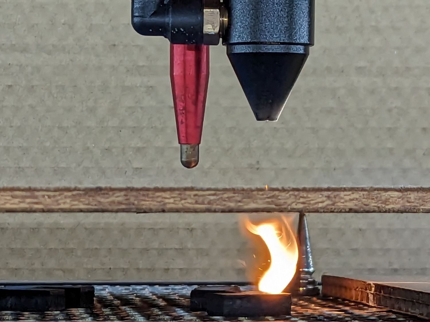
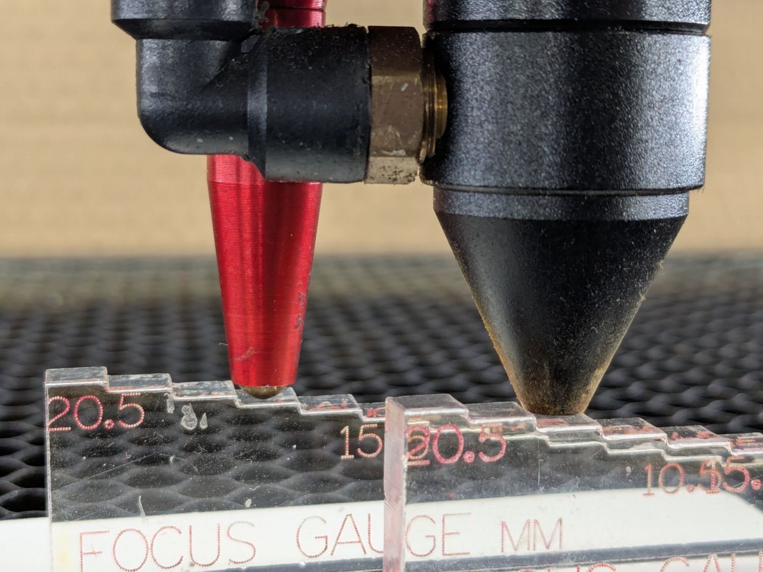
This shows the pen now flies 5 mm below the nozzle:

The step gauge shows it’s 13.5 mm above the platform, much better than the previous 5 mm.
The switch trips juuuust before the nozzle hits the material:
I should lower the pen a millimeter, but that’s in the nature of fine tuning.
Happy Dance!