Ed Nisley's Blog: Shop notes, electronics, firmware, machinery, 3D printing, laser cuttery, and curiosities. Contents: 100% human thinking, 0% AI slop.
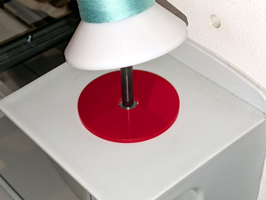
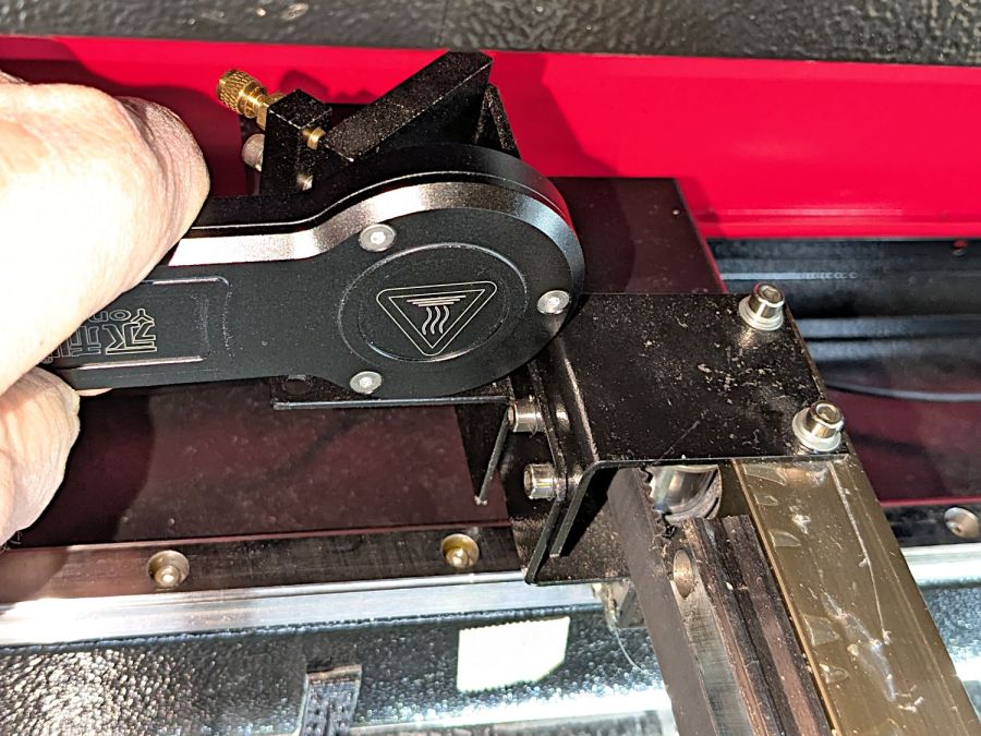
After installing (if that’s not too fancy a term) the horizontal thread spool adapter on the HQ Sixteen, I laser-cut an acrylic disk to keep thread cones centered on the other vertical spool pin:
HQ Sixteen – thread cone base locator – installed
It’s trivial: an 11 mm circle to clear the washer and a 55 mm circle to locate the cone.
However, I cut that disk with a 56 mm OD, because that’s what I measured on half a dozen cones. Come to find out at least some cone bases are juuust slightly oval and they latched onto that disk like they were gonna be best buddies forever.
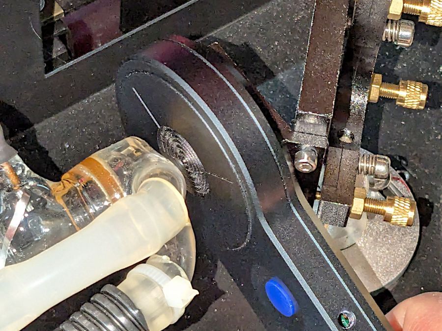
Rather than cut another acrylic disk, I laser-cut a friction ring from a scrap of stamp-pad rubber and jammed the disk against the chuck with a live center:
HQ Sixteen – thread cone base locator – turning
A few minutes of sissy cuts made the disk nicely round and concentric with the inner hole, with a little file work knocking the edges off the rim.
Clearing the clutter off the top of the laser put the monitors up on mounts clamped to its wings, which required an adapter between the monitor and the mount’s standard VESA bracket:
Acer monitor VESA adapter
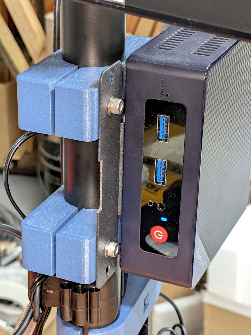
The Beelink PC has an adapter plate intended to put it on that VESA bracket, too, but a quick test showed the power button pointed downward in an inaccessible spot. I eventually realized the Beelink would fit neatly on the monitor mount’s pole:
Monitor pole Beelink clamp – front
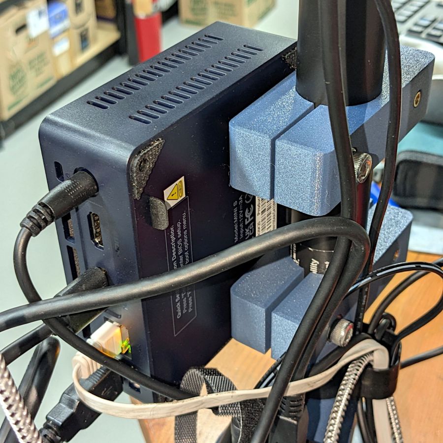
The view from the other side:
Monitor pole Beelink clamp – rear
The clamps have recesses for an M6 square nut and an M4 brass insert:
Monitor Pole BeeLink clamp – solid model
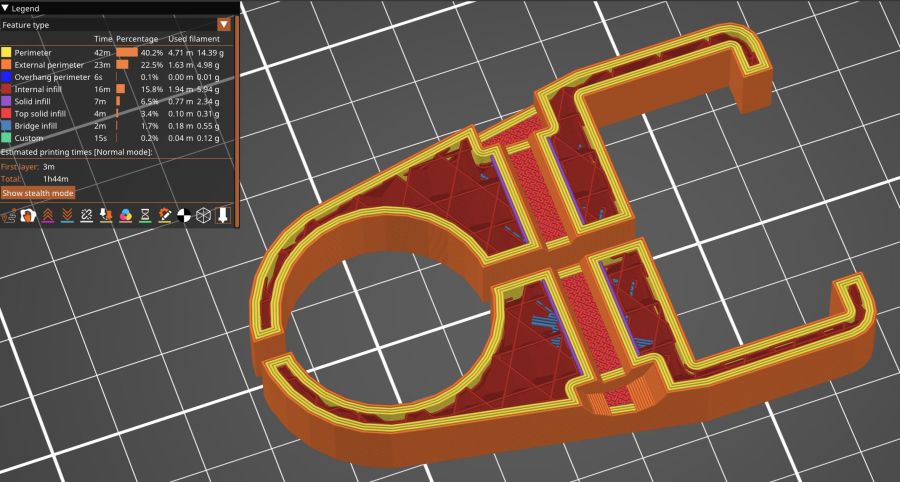
Which is better seen in a cross-section:
Monitor Pole Beelink clamp – PrusaSlicer preview
The M6 screw uses the same hex wrench as the rest of the monitor mount and the M4 screw fits the VESA bracket. Sometimes, you just gotta go with the flow.
Pondering those pictures will show why the nut and insert must be on opposite sides. I came that close to building one to throw away.
The OpenSCAD source code extrudes the overall shape upward, then punches the screw holes & fittings horizontally:
Although we had considerable success trapping voles during the last half of the 2024 gardening season, Mary found a description of what might be a better technique: a box with small entrance holes taking advantage of rodent thigmotaxis: their tendency to follow walls. The writeup shows nicely made wood boxes, but I no longer have machinery capable of cutting arbitrarily large wood slabs into pieces.
I do, however, have a vast pile of cardboard boxes:
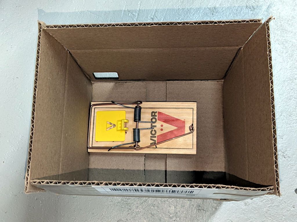
Vole Box – large
That’s a rat-size trap.
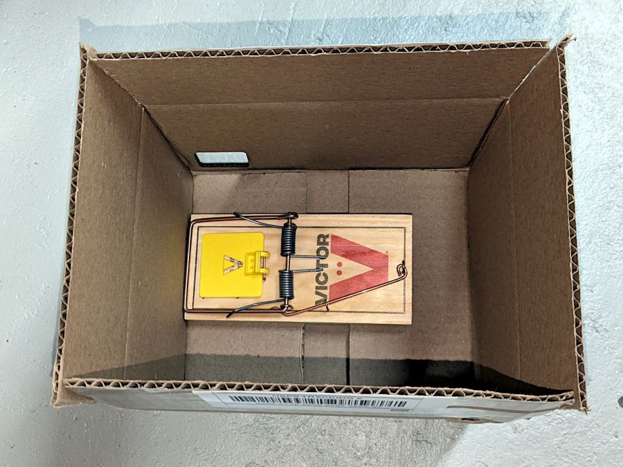
A smaller box has room for two mouse-size traps (one hidden on the left):
Vole Box – small
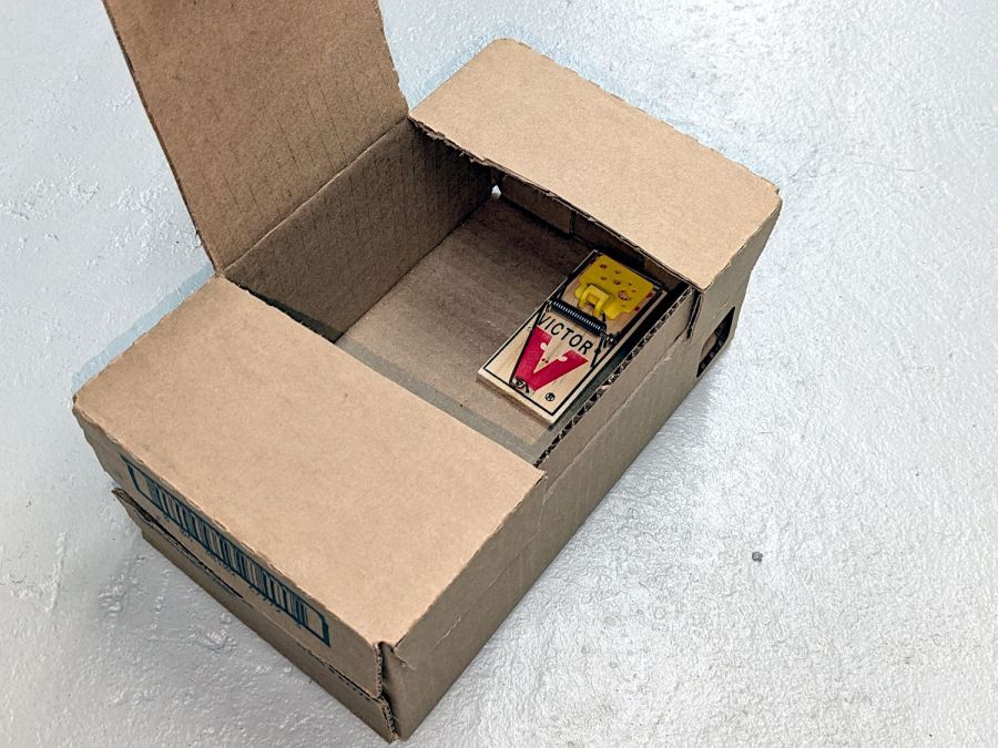
The general idea: plunk the box in a garden plot, arm the trap(s), close the lid, and eventually a vole will venture inside, whereupon wall-following leads to disaster. Apparently bait is optional, as wall-following inevitably takes them over the trap pedal. I won’t begrudge them a walnut or two, should bait become necessary.
Cardboard is obviously the wrong material for a box in an outdoor garden, but I figure they’ll survive long enough to show feasibility and I can deploy a lot of small boxes before having to conjure something more durable.
Yes, those are laser-cut rounded-rectangle holes: 30 mm and 40 mm, assuming voles care about such things.
A LightBurn video suggested large scan line intervals for decorative effects, so I adapted the SCP warning labels to fit 4 inch CD/DVD discs, set up the fixture, and Fired The Laser:
CD Engraving – fixture
The overall effect is, in most lighting, subtle:
CD Engraving – samples 2
The pair on the right with inverted engraving areas are bolder:
CD Engraving – samples 1
From a distance these two look similar, but a line interval of 0.50 mm (on the left) produces a distinct lined effect compared to the overall frosty look for 0.25 mm (open in a new tab & zoom in):
CD Engraving – vary interval
The left and right edges of the disc warp upward as the surface melts and cools, pulling the disc into a potato chip shape. Doing large areas with 0.5 mm spacing produces less warp than 0.25 mm.
The laser barely fires at 10% power (on the right) and produces a line with a distinct granular look compared the smoother result at 20% (on the left), both at 0.50 mm interval to show the lines:
CD Engraving – vary power
A 2 mm border at 0.25 mm interval (on the right, with a DVD) appears lighter than the central area at 0.50 mm (the CD on the left does not have the border):
CD Engraving – interval passes
A closer look at the border:
CD Engraving – low power irregularity
The reason behind the granular effect at 10% power is more obvious with higher magnification:
The border and the central area happen on two different passes, so it’s comforting to see how closely the scan lines match.
I glued pairs of discs together with E6000 adhesive to discover whether it’s less awful than cutting and aligning adhesive sheets. Yup, much better, but white adhesive requires better path control to keep it out of the transparent ring around the hub and better quantity control to prevent blobs from squooshing out around the perimeter. Using clear adhesive would help, as would a fresh tube without a plug of cured gunk blocking the nozzle.
With the manual laser pulse button in place, I measured the beam power at the entry and exit planes of Mirror 1 and Mirror 2, with the differences indicating something about the reflectivity (or lack thereof) of the molybdenum mirrors. Given that the losses are on the order of a few percent, tops, I expected this to be below the repeatability of the measurements.
The Mirror 1 entry point is basically the same as the laser tube exit:
HLP-200B – Laser tube exit
The Mirror 1 exit plane is perpendicular to that, just behind the mirror, but there is no way I can get a picture of the arrangement. Suffice it to say I do not want to ever put any body parts that close to an operating laser tube again.
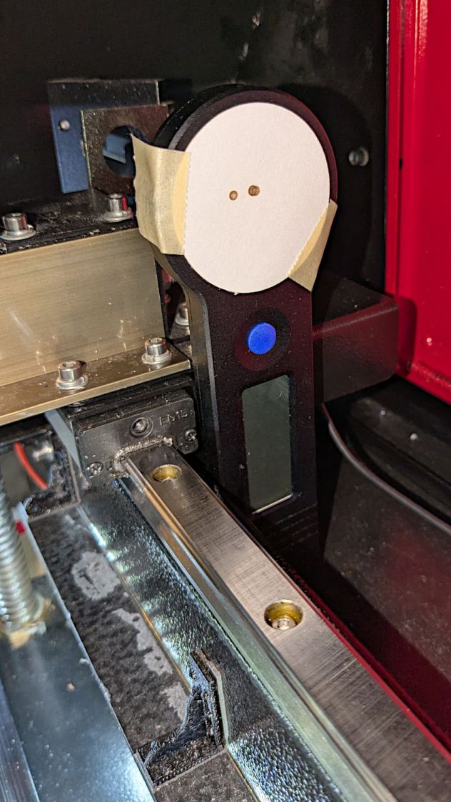
The HLP-200B meter turned out to be exactly the right length to stand on its own in front of Mirror 2, although I needed a few test shots to figure out the lateral positioning:
HLP-200B Mirror 2 entry check
The Mirror 2 exit measurements were hand-held, with the meter braced against the mirror mount brackets on the gantry:
HLP-200B Mirror 2 exit
Without further ado, the results:
M1 Entry
M1 Exit
M2 Entry
M2 Exit
35.5
31.2
30.3
32.9
28.3
30.6
29.1
32.6
31.8
22.8
27.8
28.9
30.3
29.0
29.4
28.5
26.9
28.4
28.7
27.0
31.1
31.7
28.6
26.9
30.7
29.0
29.0
29.5
2.99
3.27
0.84
2.67
The bold line gives the average of the six measurements at each position, with the sample standard deviation below that.
As expected, the pulse-to-pulse variations swamp any actual differences between the entry and exit power levels; Mirror 2 does not have a net power gain. A 2% loss in the mirror is 0.6 W at 30 W, obviously far too small for the HLP-200B meter to resolve.
The light is unavoidably upside-down from the industrial standard, because I can’t don’t want to mount it on the laser cabinet, and my use of color does not match the industrial convention. Neither of which matter for my simple needs.
The blue and orange lights turn on when their inputs are active, so they positively show sensor satisfaction, rather than laser-disabling dissatisfaction. The entire stack lights up while the controller runs a job with assist air turned on, which is usually the case.
(See below for a slipstream update.)
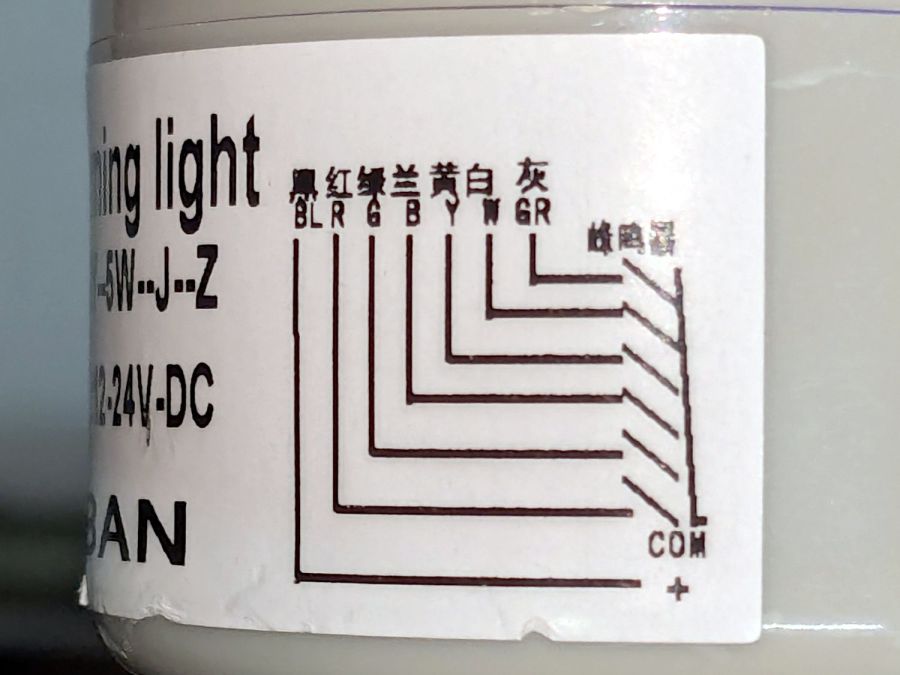
The wiring diagram on the case is the only documentation enclosed with the stack light:
Stack Light – label diagram
Any power supply between 12 VDC and 24 VDC will work and, contrary to the label, the COM lead can be either polarity: the light works in either common-anode or common-cathode configuration. Because the laser controller inputs and outputs are all low-active, I wired the COM terminal to +24 V, so pulling the other leads to GND turns on their lights.
The overall connection diagram, in order from easy to hard:
Stack Light – wiring diagram
Some of the details behind the diagram explain what’s going on.
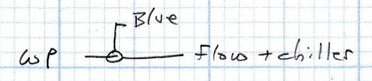
Stack Light – water protect wiring diagram
The water flow sensor is wired in series with the chiller, with a GND connection on the far end pulling the WP controller terminal low when both sensors are happy; the switches can handle another 50 mA of LED current with no problem.
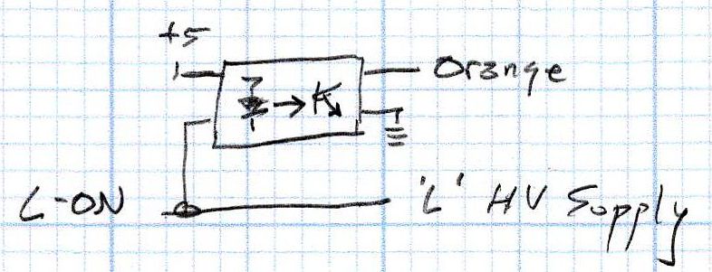
Stack Light – L-ON wiring diagram
The HV power supply has an internal pullup to +5 V on its L terminal, which means the L-ON output terminal sits at +5 V when the laser tube is off. Connecting the stack light directly to the L-ON terminal dumps the LED current into the 5 V supply through the pullup resistor, producing a somewhat weak glow in the LED when it should be off.
Running the optoisolator input from 5 V solves that problem, as its diode will be off when the L-ON output is high. When it’s low, the diode turns on, the isolator’s output transistors conduct, and the stack light gets the full 24 V it expects.
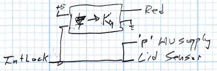
Stack Light – lid sensor wiring diagram
The lid sensor normally goes only to the IntLock controller terminal, but I also ran it to the otherwise unused P terminal on the HV power supply, in the possibly misguided belief it would prevent the supply from firing with the lid up if it failed like the first one. Those two inputs have 5 V pullups, so the optoisolator handles the stack light’s 24 V supply.
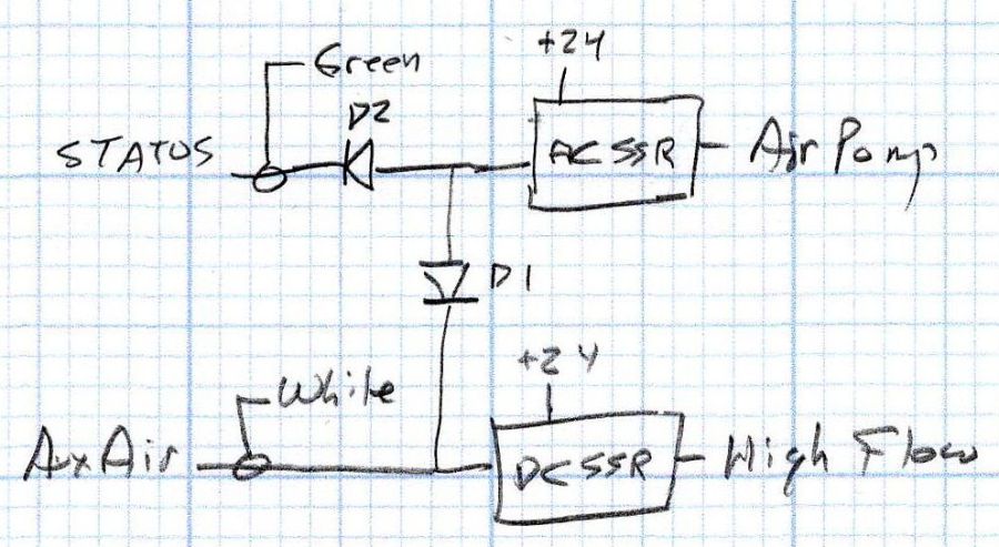
Stack Light – status and assist air wiring diagram
When I added the dual-path air assist plumbing, diode D1 turned on the air pump when either the Statusor the AuxAir output turned on. When the job calls for assist air, the AuxAir output opens a valve to increase the air flow.
The Status output is active when the controller is running a job and that’s generally the only time the AuxAir output will be active, but the machine console has an Air button that manually activates it, so diode D2 isolates the Status output in that unusual situation.
Slipstream update: I realized swapping the green & orange lights would make more sense: