Ed Nisley's Blog: Shop notes, electronics, firmware, machinery, 3D printing, laser cuttery, and curiosities. Contents: 100% human thinking, 0% AI slop.
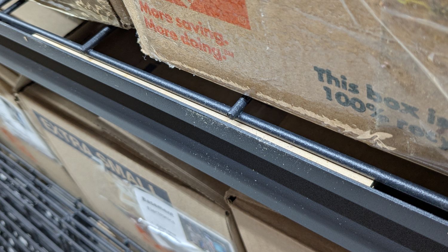
I’m finallyassembling the shelves for the last of the boxes cluttering the basement floor. Because the top of the wire shelf grid sits 4 mm below the top of the shelf rails, surely for some good reason, that pale strip is a 6 mm shim raising the grid just enough to let the boxes slide easily off without having to lift them over the rail.
It’s a pair of 3 mm thick MDF strips stuck together with tapeless sticky (a thin adhesive layer on backing paper), with the same adhesive holding the shim to the rail while I lay them down and plunk the shelf grid on top:
Wire Shelf Shim – side view
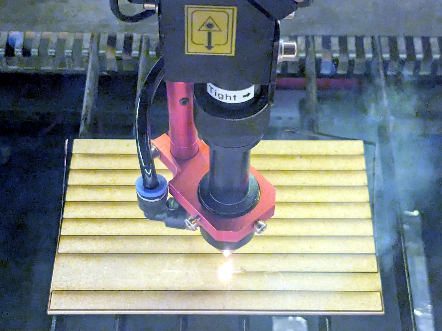
I made two sets of shims to fit the support rod spacing, with lengths carefully chosen to match two stacks from my Big Box o’ MDF Cutoffs, all 10 mm wide to fit the shelf rails:
Wire Shelf Shim – laser cutting
Admittedly, not all of the neatly rounded corners came through, due to slight variations in MDF sizing / Print-and-Cut alignment / whatever, but it’s a nearly zero waste way to turn stock into strips.
Each shelf needs 14 shims = 28 strips and I’m here to tell you if I had to bandsaw 140 little strips for each of three sets of shelves, well, I:
Probably wouldn’t ever get around to making them
Definitely would grumble about lifting those boxes, forever
Although the images are algorithmically generated in a common layout, figuring out how to get the outlines as paths seemed to require a journey into the depths of the Pygame library and that would turn into a major digression.
Instead, start with one of the webp images:
sq_RGBY
The deliberate blurring apparently simulates what you see in real life.
Import the image into LightBurn, which converts it to grayscale under the plausible assumption you’re going to engrave the image on something. Then:
Create a rounded rectangle overlaying the lower-left-most subpixel to good eyeballometric accuracy
Turn it into a four-element rectangular array, twiddling the center-to-center spacing to match the subpixel layout
Duplicate those four upward in another array to create a subpixel block, as marked in the upper-left corner of the original image
Slam another array across the bottom row and upward, twiddling the spacing to match the subpixel block spacing along both axes
Which eventually looks like this:
SubPixels – LightBurn vector overlay
I made the final array absurdly large, cropped it with a square to match the template I used for the layered paper patterns, resized the result to be 170 mm on a side, then dropped the square into the middle of the template:
Subpixel Zoo – Quattron RGBY – LightBurn black mask layer
One gotcha: crop the subpixels on a Fill layer so LightBurn will close the truncated edges, then put them on a Line layer for cutting. The doc explains why, although it’s not obvious at first, as is the fact that you must delete the group of shapes outside the square before it looks like anything happened during the cut operation.
The resulting layout contains all the subpixel rectangles, so it’s what you want for the top black mask layer. Duplicate the pattern and delete the subpixels corresponding to each color, until you have one template for each of the Red / Green / Blue layers:
Subpixel Zoo – Quattron RGBY – LightBurn layers
The blank over on the right is the Yellow layer, which does get a quartet of layer ID holes cut in the lower right corner.
Then it’s just a matter of cutting the blanks, locating the fixture on the platform, dropping the appropriate color sheet in place, cutting it, then assembling the stack in the gluing fixture:
Subpixel Zoo – Quattron RGBY
It’s kinda cute, in a techie way.
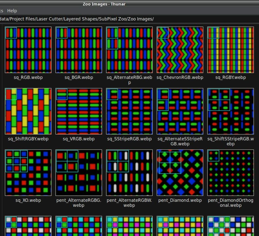
I did a bunch of layouts, just to see what they looked like:
Subpixel Zoo – 8×8 layouts
In person, the RGBY patterns look bright and the RGB patterns seem dull by comparison. I’m using cardstock paper, rather than fancy art paper, which surely makes all the difference.
Both of those “projects”, which may be too grand a term, went from “I need a thing” to having one in hand over the course of a few minutes yesterday. Neither required a great deal of thought, having previously worked out the proper speed / power settings to cut 3 mm MDF and 1 mm cork.
Other folks may lead you to believe lasers are all about fancy artwork and elaborate finished products. Being the type of guy who mostly fixes things, I’d say lasers are all about making small and generally simple parts, when and where they’re needed, to solve a problem nobody else has.
Perhaps I should devote more attention to using fancy wood with a hand-rubbed wax finish, but MDF fills my simple needs.
With a laser and a 3D printer, shop tools have definitely improved since the Bad Old Days!
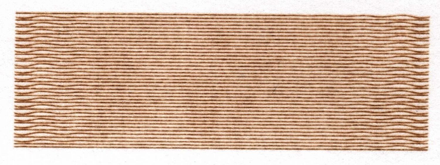
The rectangle is 30×10 mm, with lines spaced 0.25 mm apart to simplify estimating distances (although I also have a measuring magnifier) and run at 100 mm/s to simplify converting distance to time. The lines alternate in direction, beginning with a left-to-right line at the bottom (which is bar-straight from the initial positioning move). The wobbles occur at the start of each line.
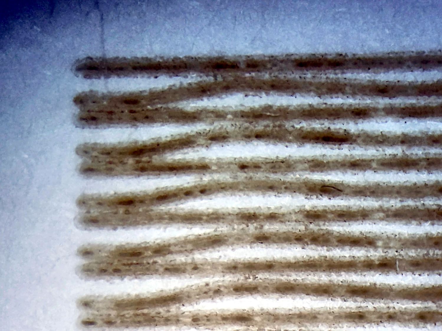
A closer look with blown contrast:
Engraving – 100mm-s 0.25mm interval 9pct – detail
The maximum error in the Y axis direction looks like 0.12 mm and damps out after 3 cycles. Each cycle covers 2.8 mm = 28 ms = 35 Hz.
The LightBurn Preview shows a 1.5 mm overscan distance and extrapolating the wobbulations leftward suggests the gantry starts the scan line with an overshoot due to the Y axis motion. The cycle-to-cycle damping is about 50%, so the initial overshoot (invisible in the overscan region) might be 0.25 mm, agreeing reasonably well with the 0.2 mm seen while cutting small squares.
The results above come from these settings:
Layer speed: 100 mm/s
Line interval: 0.25 mm
Y acceleration: 2000 mm/s²
Y start speed: 20 mm/s
I then made single-variable changes to the Engraving Parameters settings:
Line shift speed
500 mm/s
10 mm/s
Y Acceleration
200 mm/s²
Y start speed
30 mm/s
Today I Learned: The Y Start Speed (in mm/s) for engraving is capped by the Y Axis Jumpoff Speed (in mm/s², so perhaps the maximum change in speed), which is, in turn, capped at 80 mm/s.
Each of the variations produced a result visually indistinguishable from the image you see above: the error magnitude and oscillation frequency were identical.
One possible reason: None of those settings have any effect, because LightBurn doesn’t do whatever the Ruida controller defines as Engraving. However, changing both the Y start speed and the Jumpoff speedshould have made at least a little change to the results and did not.
Another possible reason: Each 0.25 mm Y axis change requires 20.8 motor steps (either 20 or 21 at 12 µm/step), so the fancy tweaks lack space to take effect, the motor thumps 20-ish steps, and the gantry shakes the same way every time.
I adjusted the laser power to compensate for the speed, with the result being a line burned into white cardboard. The lines are a bit under 0.2 mm wide, roughly the width of the focused spot.
The controller settings for the X and Y axes:
KT332N – X Y Axis Parameters – 2025-02-18
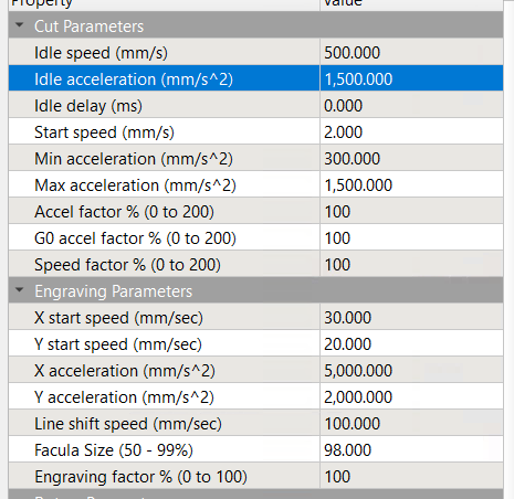
The acceleration values may be affected by the limits in this section:
KT332N – Cut Engraving Parameters – 2025-02-18
Assuming the Y axis acceleration is 3000 mm/s², the RepRap calculator shows the Y axis speeds within the 30 mm distance along the vertical sides:
RepRap Accel Calculator – 3000mm-s2 30mm
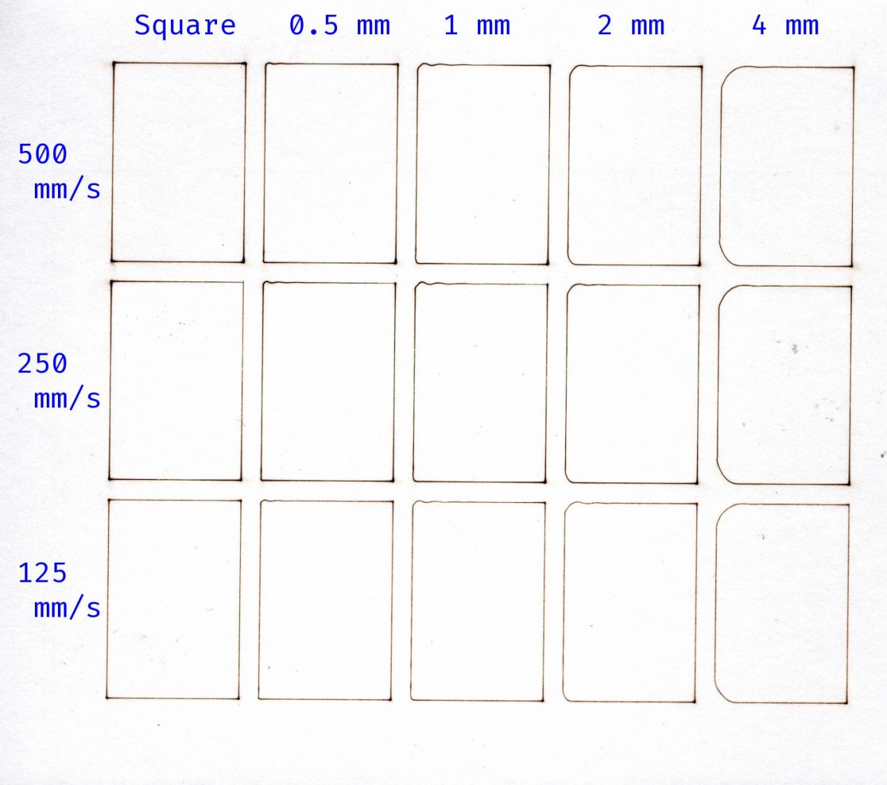
Extracting the useful bits and lining them up for comparison:
Cornering – detail
The first column in the test results shows perfectly square corners have no problem at any speed, because the controller decelerates to nearly a stop before changing direction.
Rounding the corner to 0.5 mm introduces a distinct wobble in the Y axis that doesn’t change much, probably because the controller still decelerates as it approaches the corner.
The 1 mm radius corners show a distinct overshoot at all speeds. The peak overshoot doesn’t change much between 250 and 500 mm/s, because the RepRap calculator shows the machine barely reaches 250 mm/s by the middle of the side, so 500 mm/s isn’t any faster.
The first overshoot is about 0.2 mm, the first undershoot is a little over 0.1 mm, and the rest are barely visible.
The 2 and 4 mm radius corners have barely visible wobbles. Whether that is due to the head not flexing as much due to the lower acceleration around the larger radius I cannot say.
The machine may not follow the simple RepRap acceleration profile when approaching a corner, let alone a rounded corner.
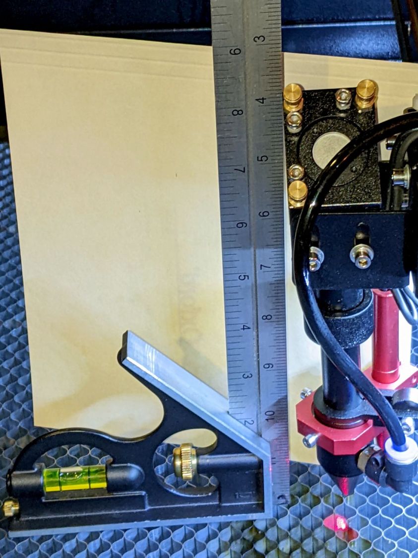
I think attempting to reduce the overshoot by fiddling with the belt tension / hardware fasteners / whatever will be unavailing. The laser head runs on a linear rail along the gantry with plenty of unbalanced mass hanging off the bottom:
OMTech 60W beam alignment – head X plane
Moving the beam 0.2 mm on the platform by pivoting around the rail 6 inch = 150 mm above amounts to only 0.08°, far less than anything I can measure while adjusting the mechanics.
Slowing down doesn’t help nearly as much as I expected and rounding the corners makes it worse.
Word has it that much spendier machines behave better, which is both comforting and unhelpful.
For whatever reason, the Thunar file browser in XFCE does not automagically show thumbnails for webp images. Some searching produced a recipe, although the displayed webp.xml file needs the last two lines to close the tags: