
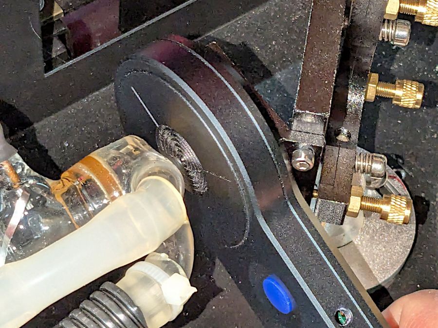
With the manual laser pulse button in place, I measured the beam power at the entry and exit planes of Mirror 1 and Mirror 2, with the differences indicating something about the reflectivity (or lack thereof) of the molybdenum mirrors. Given that the losses are on the order of a few percent, tops, I expected this to be below the repeatability of the measurements.
The Mirror 1 entry point is basically the same as the laser tube exit:
The Mirror 1 exit plane is perpendicular to that, just behind the mirror, but there is no way I can get a picture of the arrangement. Suffice it to say I do not want to ever put any body parts that close to an operating laser tube again.
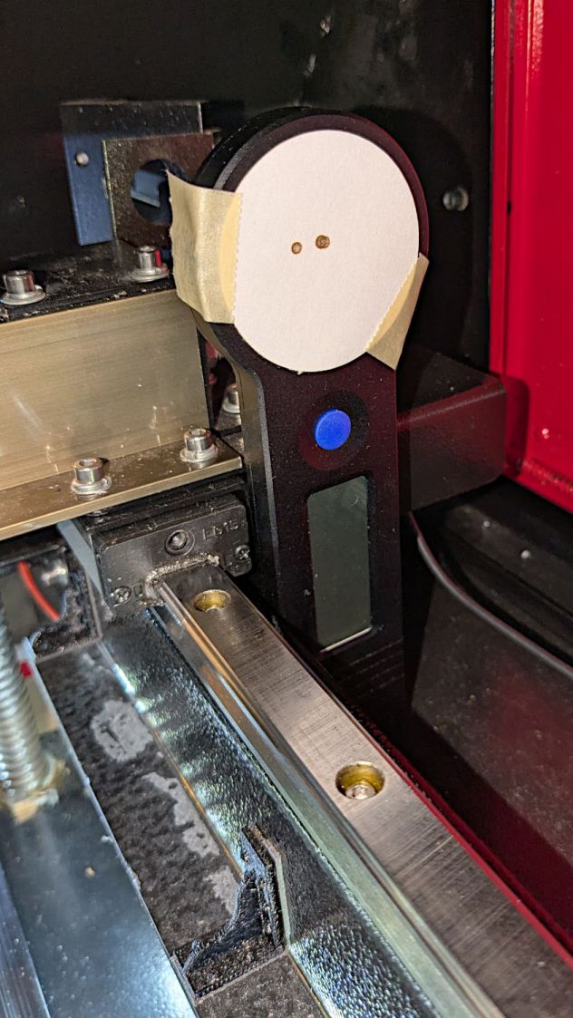
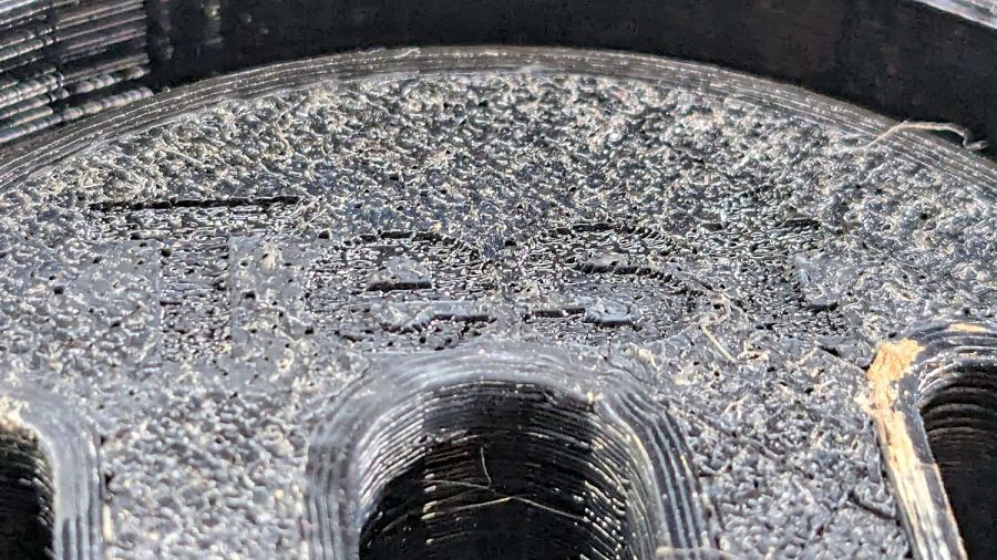
The HLP-200B meter turned out to be exactly the right length to stand on its own in front of Mirror 2, although I needed a few test shots to figure out the lateral positioning:
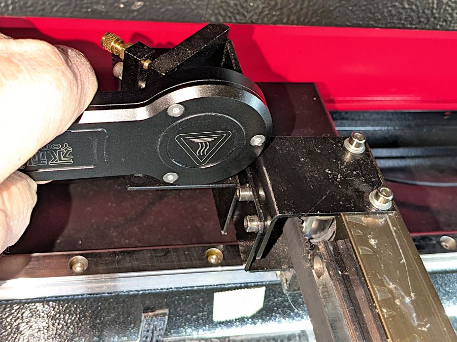
The Mirror 2 exit measurements were hand-held, with the meter braced against the mirror mount brackets on the gantry:
Without further ado, the results:
| M1 Entry | M1 Exit | M2 Entry | M2 Exit |
| 35.5 | 31.2 | 30.3 | 32.9 |
| 28.3 | 30.6 | 29.1 | 32.6 |
| 31.8 | 22.8 | 27.8 | 28.9 |
| 30.3 | 29.0 | 29.4 | 28.5 |
| 26.9 | 28.4 | 28.7 | 27.0 |
| 31.1 | 31.7 | 28.6 | 26.9 |
| 30.7 | 29.0 | 29.0 | 29.5 |
| 2.99 | 3.27 | 0.84 | 2.67 |
The bold line gives the average of the six measurements at each position, with the sample standard deviation below that.
As expected, the pulse-to-pulse variations swamp any actual differences between the entry and exit power levels; Mirror 2 does not have a net power gain. A 2% loss in the mirror is 0.6 W at 30 W, obviously far too small for the HLP-200B meter to resolve.
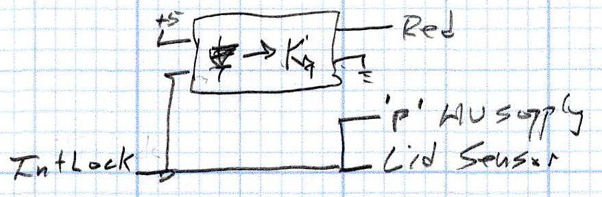
I must once again set up the photocell to measure the stray IR scattered around the beam, measure the actual tube current, then see if the two vary as much as the HLP-200B says the beam power does.


