|
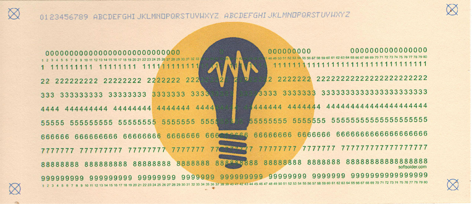
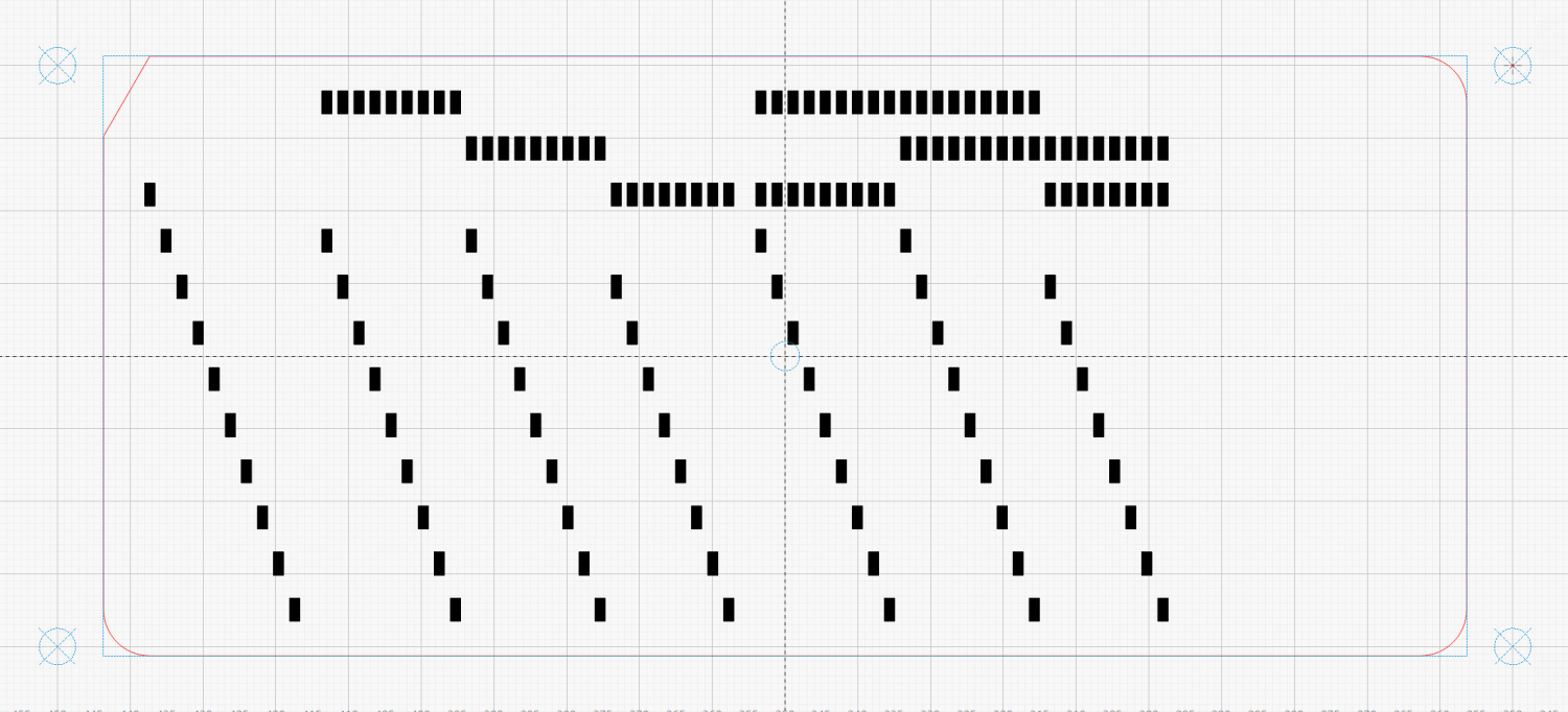
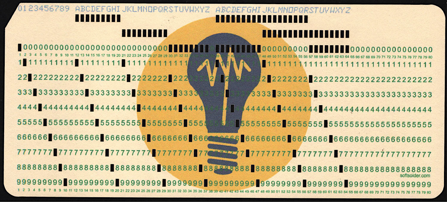
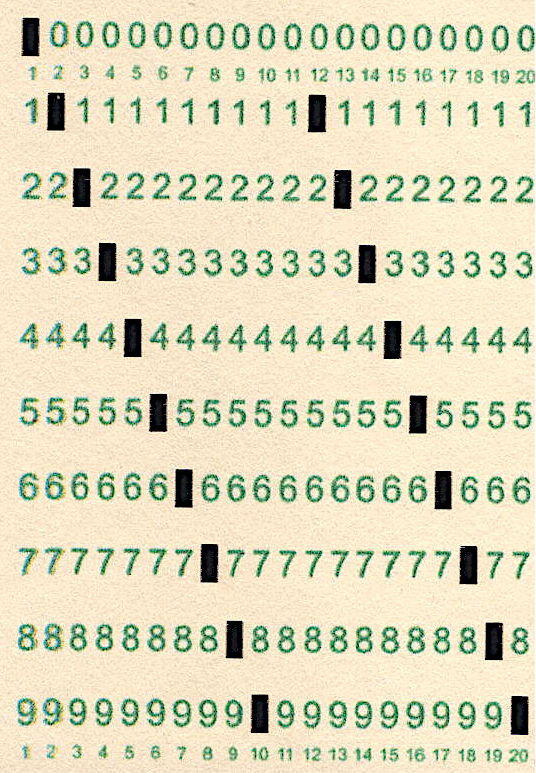
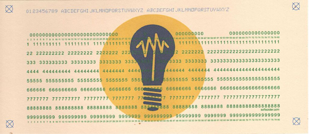
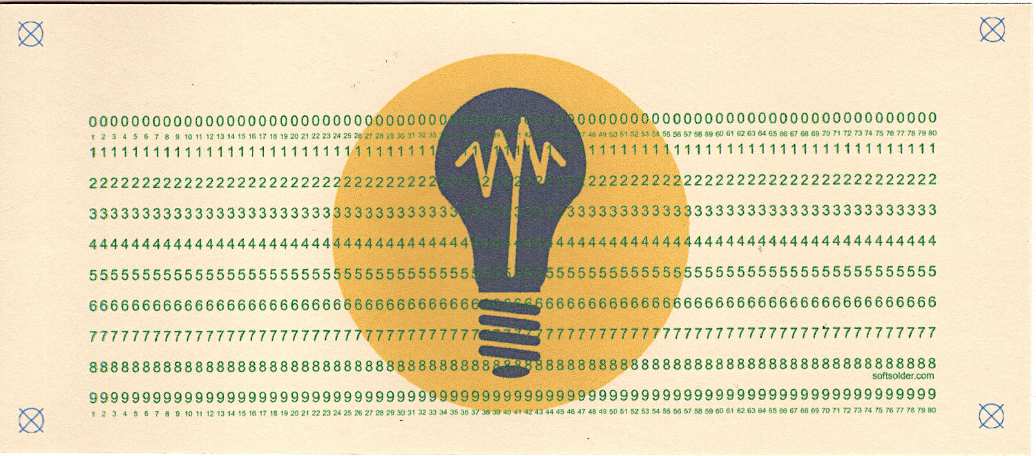
# Generator for punched cards |
|
# Ed Nisley – KE4ZNU |
|
# 2026-01-20 cargo-culted from various sources |
|
|
|
import svg |
|
import math |
|
from argparse import ArgumentParser |
|
from pathlib import Path |
|
import curses.ascii |
|
import itertools |
|
|
|
INCH = 25.4 |
|
X = 0 |
|
Y = 1 |
|
|
|
SVGSCALE = 96.0/25.4 # converts "millimeters as SVG points" to real millimeters |
|
|
|
parser = ArgumentParser(description="Create SVG files to print & laser-cut a punched card") |
|
|
|
parser.add_argument('–debug',action='store_true', |
|
help="Enable various test outputs, do not use XML file") |
|
parser.add_argument('–lower',action='store_true', |
|
help="Fake lowercase with italics") |
|
parser.add_argument('–test', type=int, choices=range(7), default=0, |
|
help="Various test patterns to verify card generation") |
|
parser.add_argument('–lbsvg', action='store_true', |
|
help="Work around LightBurn SVG issues") |
|
parser.add_argument('–layout', default="print", choices=["laser","print"], |
|
help="Laser-engrave hole & char text into card") |
|
parser.add_argument('–seq',type=int, default=0, |
|
help="If nonzero, use as squence number in col 72-80") |
|
parser.add_argument('–logofile', default="Card logo.png", |
|
help="Card logo filename") |
|
parser.add_argument('–prefix', default="", |
|
help="Card number prefix, no more than 5 characters") |
|
parser.add_argument('contents',nargs="*",default='Your text goes here', |
|
help="Line of text to be punched on card") |
|
args = parser.parse_args() |
|
|
|
PageSize = (round(8.5*INCH,3), round(11.0*INCH,3)) # sheet of paper |
|
|
|
CardSize = (7.375*INCH,3.25*INCH) # punch card bounding box |
|
|
|
NumCols = 80 |
|
NumRows = 12 |
|
|
|
HoleSize = (0.055*INCH,0.125*INCH) # punched hole |
|
HoleOC = (0.087*INCH,0.250*INCH) |
|
|
|
BaseHoleAt = (0.251*INCH,0.250*INCH) # center point |
|
|
|
TargetOC = (200,80) # alignment targets around card |
|
TargetOD = 5 |
|
|
|
#— map ASCII / Unicode characters to rows |
|
# rows are names, not indexes: Row 12 is along the top of the card |
|
# Row 10 is the same as Row 0 |
|
|
|
CharMap = { |
|
" ": (), |
|
"0": (0,), |
|
"1": (1,), |
|
"2": (2,), |
|
"3": (3,), |
|
"4": (4,), |
|
"5": (5,), |
|
"6": (6,), |
|
"7": (7,), |
|
"8": (8,), |
|
"9": (9,), |
|
"A": (12,1), |
|
"B": (12,2), |
|
"C": (12,3), |
|
"D": (12,4), |
|
"E": (12,5), |
|
"F": (12,6), |
|
"G": (12,7), |
|
"H": (12,8), |
|
"I": (12,9), |
|
"J": (11,1), |
|
"K": (11,2), |
|
"L": (11,3), |
|
"M": (11,4), |
|
"N": (11,5), |
|
"O": (11,6), |
|
"P": (11,7), |
|
"Q": (11,8), |
|
"R": (11,9), |
|
"S": (10,2), |
|
"T": (10,3), |
|
"U": (10,4), |
|
"V": (10,5), |
|
"W": (10,6), |
|
"X": (10,7), |
|
"Y": (10,8), |
|
"Z": (10,9), |
|
"a": (12,10,1), |
|
"b": (12,10,2), |
|
"c": (12,10,3), |
|
"d": (12,10,4), |
|
"e": (12,10,5), |
|
"f": (12,10,6), |
|
"g": (12,10,7), |
|
"h": (12,10,8), |
|
"i": (12,10,9), |
|
"j": (12,11,1), |
|
"k": (12,11,2), |
|
"l": (12,11,3), |
|
"m": (12,11,4), |
|
"n": (12,11,5), |
|
"o": (12,11,6), |
|
"p": (12,11,7), |
|
"q": (12,11,8), |
|
"r": (12,11,9), |
|
"s": (10,11,2), |
|
"t": (10,11,3), |
|
"u": (10,11,4), |
|
"v": (10,11,5), |
|
"w": (10,11,6), |
|
"x": (10,11,7), |
|
"y": (10,11,8), |
|
"z": (10,11,9), |
|
"¢": (12,2,8), |
|
".": (12,3,8), |
|
"<": (12,4,8), |
|
"(": (12,5,8), |
|
"+": (12,6,8), |
|
"|": (12,7,8), |
|
"!": (11,2,8), |
|
"$": (11,3,8), |
|
"*": (11,4,8), |
|
")": (11,5,8), |
|
";": (11,6,8), |
|
"¬": (11,7,8), |
|
",": (10,3,8), |
|
"%": (10,4,8), |
|
"_": (10,5,8), |
|
">": (10,6,8), |
|
"?": (10,7,8), |
|
":": (2,8), |
|
"#": (3,8), |
|
"@": (4,8), |
|
"'": (5,8), |
|
"=": (6,8), |
|
'"': (7,8), |
|
"&": (12,), |
|
"-": (11,), |
|
"/": (10,1), |
|
"█": (12,11,10,1,2,3,4,5,6,7,8,9), # used for lace card test pattern |
|
"▯": (12,10,2,4,6,8), # used for alignment tests with hack for row numbers |
|
} |
|
|
|
#— map row name to physical row offset from top |
|
|
|
RowMap = (2,3,4,5,6,7,8,9,10,11,2,1,0) |
|
|
|
RowGlyphs = "0123456789⁰¹²▯" # last four should never appear, hollow box is a hack |
|
|
|
#— pretty punch patterns |
|
|
|
TestStrings = ( " " * NumCols, # blank card for printing |
|
"█" * NumCols, # lace card for amusement |
|
"0123456789 ABCDEFGHIJKLMNOPQRSTUVWXYZ abcdefghijklmnopqrstuvwxyz", |
|
"¢.<(+|!$*);¬,%_>?:#@'=" + '"' + "&-/█", |
|
"▯" * NumCols, # hack for row number alignment |
|
) |
|
|
|
#— LightBurn layer colors |
|
|
|
HoleCut = "black" # C00 Black |
|
CardMark = "blue" # C01 Blue |
|
CardCut = "red" # C02 Red |
|
CardText = "green" # C03 Green |
|
CardGray = "rgb(125,135,185)" # C17 Dark Gray |
|
Tooling = "rgb(12,150,217)" # T2 Tool |
|
|
|
#— LightBurn uses only the stroke |
|
|
|
DefStroke = 0.20 |
|
DefFill = "none" |
|
|
|
#——————— |
|
# Set up card contents |
|
|
|
if args.test: # test patterns used without changes |
|
Contents = TestStrings[args.test – 1].ljust(NumCols,' ') |
|
|
|
else: # real cards need cleaning |
|
Contents = ''.join(itertools.chain(*args.contents)) |
|
|
|
if args.seq: |
|
nl = 8 – len(args.prefix) |
|
Contents = Contents.ljust(NumCols – 8,' ')[:(NumCols – 8)] |
|
Contents = Contents + f"{args.prefix}{args.seq:0{nl}d}" |
|
else: |
|
Contents = Contents.ljust(NumCols,' ')[:NumCols] |
|
|
|
if not args.lower: |
|
Contents = Contents.upper() |
|
|
|
|
|
|
|
#— accumulate tooling layout |
|
|
|
ToolEls = [] |
|
|
|
# mark center of card for drag-n-drop location |
|
|
|
if args.layout == "laser": |
|
ToolEls.append( |
|
svg.Circle( |
|
cx=svg.mm(CardSize[X]/2), |
|
cy=svg.mm(CardSize[Y]/2), |
|
r="2mm", |
|
stroke=Tooling, |
|
stroke_width=svg.mm(DefStroke), |
|
fill="none", |
|
) |
|
) |
|
# mark card perimeter for alignment check |
|
|
|
if args.layout == "laser": |
|
ToolEls.append( |
|
svg.Rect( |
|
x=0, |
|
y=0, |
|
width=svg.mm(CardSize[X]), |
|
height=svg.mm(CardSize[Y]), |
|
stroke=Tooling, |
|
stroke_width=svg.mm(DefStroke), |
|
fill="none", |
|
) |
|
) |
|
|
|
#— accumulate alignment targets |
|
|
|
MarkEls = [] |
|
|
|
# alignment targets |
|
|
|
for c in ((1,1),(-1,1),(-1,-1),(1,-1)): |
|
ctr = (CardSize[X]/2 + c[X]*TargetOC[X]/2,CardSize[Y]/2 + c[Y]*TargetOC[Y]/2) |
|
MarkEls.append( |
|
svg.Circle( |
|
cx=svg.mm(ctr[X]), |
|
cy=svg.mm(ctr[Y]), |
|
r=svg.mm(TargetOD/2), |
|
stroke=Tooling if args.layout == "laser" else CardMark, |
|
stroke_width=svg.mm(DefStroke), |
|
fill="none", |
|
) |
|
) |
|
MarkEls.append( |
|
svg.Path( |
|
d=[ |
|
svg.M(ctr[X] + TargetOD/2,ctr[Y] – TargetOD/2), |
|
svg.l(-TargetOD,TargetOD), |
|
svg.m(0,-TargetOD), |
|
svg.l(TargetOD,TargetOD), |
|
], |
|
transform="scale(" + repr(1.0 if args.lbsvg else SVGSCALE) + ")", |
|
stroke=Tooling if args.layout == "laser" else CardMark, |
|
stroke_width=svg.mm(DefStroke if args.lbsvg else DefStroke/SVGSCALE), |
|
fill="none", |
|
) |
|
) |
|
|
|
#— accumulate card cuts |
|
|
|
CardEls = [] |
|
|
|
# card perimeter with magic numbers from card dimensions |
|
|
|
if args.layout == "laser": |
|
CardEls.append( |
|
svg.Path( |
|
d=[ |
|
svg.M(0.25*INCH,0), |
|
svg.h(CardSize[X] – 2*0.25*INCH), |
|
svg.a(0.250*INCH,0.25*INCH,0,0,1,0.25*INCH,0.25*INCH), |
|
svg.v(CardSize[Y] – 2*0.25*INCH), |
|
svg.a(0.25*INCH,0.25*INCH,0,0,1,-0.25*INCH,0.25*INCH), |
|
svg.H(0.25*INCH), |
|
svg.a(0.25*INCH,0.25*INCH,0,0,1,-0.25*INCH,-0.25*INCH), |
|
svg.V(0.25*INCH/math.tan(math.radians(30))), |
|
svg.Z(), |
|
], |
|
transform="scale(" + repr(1.0 if args.lbsvg else SVGSCALE) + ")", |
|
stroke=CardCut if args.layout == "laser" else Tooling, |
|
stroke_width=svg.mm(DefStroke if args.lbsvg else DefStroke/SVGSCALE), |
|
fill="none", |
|
), |
|
) |
|
|
|
# label hole positions in rows 0-9 |
|
# special hack for outline boxes |
|
|
|
TextEls = [] |
|
|
|
if args.layout == "print": |
|
xoffset = 0.3 # tiny offsets to align chars with cuts |
|
yoffset = 1.5 |
|
for c in range(NumCols): |
|
glyph = Contents[c] |
|
rnx = CharMap[glyph] # will include row name 10 aliased as row name 0 |
|
for rn in range(10): |
|
pch = RowGlyphs[rn] # default is digit for row |
|
if ((rn in rnx) or ((rn == 0) and (10 in rnx))): # suppress punched holes |
|
pch = "▯" if glyph == "▯" else " " # except for alignment tests |
|
r = RowMap[rn] |
|
TextEls.append( |
|
svg.Text( |
|
x=svg.mm(BaseHoleAt[X] + c*HoleOC[X] + xoffset), |
|
y=svg.mm(BaseHoleAt[Y] + r*HoleOC[Y] + yoffset), |
|
class_=["holes"], |
|
font_family="Arial", # required by LightBurn |
|
font_size="3.0mm", # required by LightBurn |
|
text_anchor="middle", |
|
text=pch |
|
) |
|
) |
|
|
|
# number the columns in tiny print |
|
|
|
if args.layout == "print": |
|
xoffset = 0.3 |
|
yoffset = 0.5 |
|
#xoffset = -0.25 if args.lbsvg else 0.0 # original hack |
|
for c in range(NumCols): |
|
for y in (22.7,80.0): # magic numbers between the rows |
|
TextEls.append( |
|
svg.Text( |
|
x=svg.mm(BaseHoleAt[X] + c*HoleOC[X] + xoffset), |
|
y=svg.mm(y + yoffset), |
|
class_=["cols"], |
|
font_family="Arial", # required by LightBurn |
|
font_size="1.5mm", # required by LightBurn |
|
text_anchor="middle", |
|
text=f"{c+1: 2d}", |
|
) |
|
) |
|
|
|
# add text attribution |
|
|
|
if args.layout == "print": |
|
TextEls.append( |
|
svg.Text( |
|
x=svg.mm(175.3), |
|
y=svg.mm(72.5 if args.lbsvg else 73.0), |
|
class_=["attrib"], |
|
font_family="Arial", # required by LightBurn |
|
font_size="2.0mm", # ignored by LightBurn |
|
text_anchor="middle", |
|
dominant_baseline="middle", |
|
text="softsolder.com", |
|
) |
|
) |
|
|
|
|
|
#— accumulate holes |
|
|
|
HoleEls = [] |
|
|
|
# punch the holes |
|
|
|
if args.layout == "laser": |
|
for c in range(len(Contents)): |
|
glyph = Contents[c] |
|
if not (glyph in CharMap): |
|
glyph = ' ' |
|
for rn in CharMap[glyph]: |
|
r = RowMap[rn] |
|
HoleEls.append( |
|
svg.Rect( |
|
x=svg.mm(BaseHoleAt[X] + c*HoleOC[X] – HoleSize[X]/2), |
|
y=svg.mm(BaseHoleAt[Y] + r*HoleOC[Y] – HoleSize[Y]/2), |
|
width=svg.mm(HoleSize[X]), |
|
height=svg.mm(HoleSize[Y]), |
|
stroke=HoleCut, |
|
stroke_width=svg.mm(DefStroke), |
|
fill="none", |
|
) |
|
) |
|
|
|
# print punched characters across the top edge |
|
# The KEYPUNCH029 font does not include lowercase characters, so |
|
# fake lowercase with italics, which LightBurn ignores |
|
|
|
if args.layout == "print": |
|
xoffset = 0.3 |
|
for c in range(len(Contents)): |
|
glyph = Contents[c] |
|
if not (glyph in CharMap): |
|
glyph = ' ' |
|
fc = "dottylc" if curses.ascii.islower(glyph) else "dotty" |
|
glyph = svg.escape(glyph) # escape the characters that wreck SVG syntax |
|
TextEls.append( |
|
svg.Text( |
|
x=svg.mm(BaseHoleAt[X] + c*HoleOC[X] + xoffset), |
|
y=svg.mm(5.0), # align just below card edge |
|
class_=[fc], |
|
font_family="KEYPUNCH029", # required by LightBurn |
|
font_size="4.0mm", # required by LightBurn |
|
text_anchor="middle", |
|
text=glyph |
|
) |
|
) |
|
|
|
#— assemble and blurt out the SVG file |
|
|
|
if not args.debug: |
|
canvas = svg.SVG( |
|
width=svg.mm(PageSize[X]), |
|
height=svg.mm(PageSize[Y]), |
|
elements=[ |
|
svg.Style( |
|
text = f"\n.attrib{{ font: 2mm Arial; fill:{CardText}}}" + |
|
f"\n.holes{{ font: 3.0mm Arial; fill:{CardText}}}" + |
|
f"\n.cols{{ font: 1.5mm Arial; fill:{CardText}}}" + |
|
f"\n.dotty{{ font: 4.0mm KEYPUNCH029; fill:{CardGray}}}" + |
|
f"\n.dottylc{{ font: italic 4.0mm KEYPUNCH029; fill:{CardGray}}}" |
|
), |
|
ToolEls, |
|
MarkEls, |
|
CardEls, |
|
TextEls, |
|
HoleEls, |
|
], |
|
) |
|
|
|
print(canvas) |