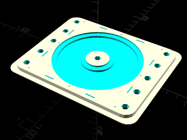
Ed Nisley's Blog: Shop notes, electronics, firmware, machinery, 3D printing, laser cuttery, and curiosities. Contents: 100% human thinking, 0% AI slop.
Tag: Improvements
Making the world a better place, one piece at a time
The CAMTool V3.3 board dispenses with fancy USB power switching circuitry:
CAMTOOL CNC-V3.3 schematic – USB Power Entry
The NUP2201 is an ESD clamp diode / suppressor IC, which is a nice touch, but FU1, a simple 300 mA polyfuse, is the only thing standing between the USB cable and the on-board +5 V regulator. In real life, it looks like this:
CAMTool V3.3 – USB power fuse
It’s the little black rectangle between the USB jack and the CH340 USB-to-serial chip. The
The far end of the USB cable plugs into a Raspberry Pi, a device known for unseemly fussiness about USB power, so I unsoldered the fuse and installed a diode:
CAMTool V3.3 – USB power diode
It’s a BAT54 Schottky diode, pointed toward the right to prevent current from the board getting to the Pi. Pin 2 (toward the bottom) isn’t connected to anything inside the package, either, so it’s all good.
I suppose if one were a stickler for detail, one could gimmick the diode in series with the fuse, but I figured that’s a solution for a problem well down on the probability list …
The X axis driver is an unmodified DRV8825 PCB operating in default mixed-decay mode. The Y axis DRV8825 has its DECAY pin pulled high, thereby putting it in fast decay mode.
The scope timebase varies to match the programmed feed rate. Because the X and Y axes move simultaneously, each axis moves at 1/√2 the programmed speed:
G1 X10 Y10 F100 → 71 mm/min on X and Y
The motor generates minimal back EMF at slow speeds, so the winding sees nearly the full supply voltage. As described in the previous post, the basic problem arises when the current rises too fast during each PWM cycle:
V = L di/dt
di/dt = 24 V / 3 mH = 8 kA/s
The first 1:32 microstep away from 0 calls for 5% of max current = 50 mA at a 1 A peak. The DRV8825 datasheet says the PWM typically runs at 30 kHz = 33 µs/cycle, during which the current will change by 270 mA:
267 mA = 8 kA/s × 33.3 µs
Notice how the current slams to a nearly constant, much-too-high value just after the first microstep. The incorrect current level decreases with lower supply voltage, because the rate-of-change decreases and the commanded current level reaches the actual (incorrect) current sooner.
Varying the motor voltage at a constant 10 mm/min:
3018 XY – Mixed Fast – 24V – 10mm-min 1A-div
3018 XY – Mixed Fast – 20V – 10mm-min 1A-div
3018 XY – Mixed Fast – 15V – 10mm-min 1A-div
3018 XY – Mixed Fast – 12V – 10mm-min 1A-div
3018 XY – Mixed Fast – 10V – 10mm-min 1A-div
Note that reducing the supply voltage doesn’t change the motor winding current, because the DRV8825 controls the current during each microstep, at least to the best of its ability.
Also note that the current overshoots the target for those microsteps, even when the motor is stopped, because there’s no back EMF, so the power dissipation is too high even at rest.
Enough back EMF appears at 100 mm/min to begin tamping down the current overshoot at 24 V:
3018 XY – Mixed Fast – 24V – 100mm-min 1A-div
The current waveform looks good at 12 V:
3018 XY – Mixed Fast – 12V – 100mm-min 1A-div
The back EMF at 1000 mm/min nearly eliminates the overshoot at 24 V, with fast decay in the Y axis causing some PWM ripple:
3018 XY – Mixed Fast – 24V – 1000mm-min 1A-div
Both decay modes look good at 12 V:
3018 XY – Mixed Fast – 12V – 1000mm-min 1A-div
At 1500 mm/min, the highest reasonable speed for the thing, and a 24 V supply, both waveforms still look good:
3018 XY – Mixed Fast – 24V – 1500mm-min 1A-div
However, the back EMF is now high enough to buck the 12 V supply, preventing the current from decreasing fast enough in mixed decay mode (top trace):
3018 XY – Mixed Fast – 12V – 1500mm-min 1A-div
Tweaking the GRBL config to allow 2000 mm/min feeds shows the waveforms starting to become triangular, even at 24 V:
3018 XY – Mixed Fast – 24V – 2000mm-min 1A-div
And a 12 V supply opposed by the back EMF simply can’t change the current fast enough to keep up with the DRV8825 microstep current levels:
3018 XY – Mixed Fast – 12V – 2000mm-min 1A-div
Bottom line: a +12 V motor supply and DRV8825 drivers modified to run in fast decay mode look like the best setup for the 3018-Pro: good current control at low speeds with enough moxie to handle higher speeds.
I should hack the DRV8825 boards into 1:8 microstep mode to reduce the IRQ rate by a factor of four, then see what happens to the back EMF at absurd speeds.
After nigh onto 18 years, the pipe straps holding the Zzipper fairing struts to the handlebars of our Tour Easy recumbents finally shrugged off their plastic wraps:
Tour Easy Zzipper Fairing – OEM mount
Although they still worked, riding over broken pavement produced distinct rattles; alas, the roads around here feature plenty of broken pavement.
The solution is a rugged plastic block capped with aluminum plates to spread the clamping load:
Tour Easy Zzipper Fairing – block mount
The solid model is straightforward:
Zzipper Fairing – Strut Mount – solid model – Show view
A slight bit of tinkering made the stack exactly the right height for 45 mm screws secured with nyloc nuts. No washers on either end, although that’s definitely in the nature of fine tuning.
The three sections print without support:
Zzipper Fairing – Strut Mount – solid model
I reamed the smaller hole with a 3/8 inch drill to match the fairing strut rod. The as-printed larger hole fit the handlebar perfectly, although the first picture shows the tubing isn’t exactly round on the near side of the block, where it starts the outward bend toward the grips.
The cap plates cried out for CNC, but I simply traced two outlines of the block on 1/8 inch aluminum sheet, bandsawed near the line, introduced them to Mr Disk Sander for finishing & corner rounding, transfer-punched the holes from the plastic blocks, and drilled to suit:
Tour Easy Zzipper Fairing – clamp plates
Making two pairs of plates by hand counts as Quality Shop Time around here.
This file contains hidden or bidirectional Unicode text that may be interpreted or compiled differently than what appears below. To review, open the file in an editor that reveals hidden Unicode characters.
Learn more about bidirectional Unicode characters
Mixed decay mode begins as fast decay, but at a fixed period of time (75% of the PWM cycle) switches to slow decay mode for the remainder of the fixed PWM period. This occurs only if the current through the winding is decreasing (per the indexer step table); if the current is increasing, then slow decay is used.
The 24 V supply on the CNC 3018-Pro provides too much voltage for the motors, because slow decay mode can’t handle those rising slopes:
3018 XY – Mixed Fast – 24V – 10mm-min 12V 1A-div
Note that “rising” means the current increases with either polarity from 0 A at the midline. The DRV8825 uses a MOSFET H-bridge to drive winding current in either direction from the +24 V motor supply voltage.
Both traces show motor winding current at 1 A/div, with the XY axes creeping along at 10 mm/min (thus, 7.1 mm/min each). The upper trace is the X axis, with a stock DRV8825 module in mixed decay mode. The lower trace is the Y axis, with its DRV8825 hacked into fast decay mode.
The basic problem, about which more later, comes from the current rising too fast during each PWM cycle:
V = L di/dt
di/dt = 24 V / 3 mH = 8 kA/s
The first 1:32 microstep away from 0 calls for 5% of max current = 50 mA at a 1 A peak. The DRV8825 datasheet says the PWM typically runs at 30 kHz = 33 µs/cycle, during which the current will change by 270 mA:
267 mA = 8 kA/s × 33.3 µs
Some preliminary measurements suggest these (probably counterfeit) DRV8825 chips actually run at 16 kHz = 66 µs/cycle:
3018 X – ripple 1 step – 18V – A0 B-90 500mA-div
During those cycles the current can increase by more than 500 mA. The first scope picture shows an abrupt increase to maybe 700 mA, so, yeah, that’s about right.
Having the wrong current in one winding means the motor isn’t positioned correctly during those microsteps. The 3018-Pro runs at (an absurd) 1600 µstep/mm, so being off by even a full step isn’t big deal in terms of positioning.
The real problem comes from running nearly 1 A through both windings. Those little motors run really hot: they’re dissipating twice what they should be.
Anyhow, the pin layout shows the DRV8825 DECAY mode selection on pin 19:
DRV8825 pinout
Which sits on an inconveniently skinny little PCB pad, fifth from the left on the bottom:
DRV8825 PCB – open Decay pin
Memo to Self: Don’t make that mistake when you lay out a PCB. Always put a little pad or via on a disconnected pin, so as to have a hand-soldering target big enough to work with.
The objective is to pull the pin high:
DRV8825 DECAY pin settings
Pin 15, in the lower left corner, provides the output of a 3.3 V linear regulator, with its PCB trace connected to the left side of the ceramic cap:
Those are two different PCBs. The crappy TI logos, not easily visible in those low-res pix, on both ICs suggest they’re by-now-typical counterfeits, so seeing a factor-of-two difference in PWM frequency isn’t surprising.
So this happened when I grabbed an alligator clip lead:
Dual Alligator Clip Collection
My coax cable and clip lead collection includes everything from “I’ve had it forever” to “Recent cheap crap”, including much of Mad Phil’s collection. Some of the recent crap included Chinese clip leads with what can charitably be described as marginal connections:
Alligator clips – bent wire
The insulation may provide some compliance in the crimp, but the alligator clip itself consists of cheap steel which won’t hold a crimp, even if it was crimped firmly to start with.
As a rule, the crimps aren’t particularly good:
Black Dual Alligator – as manufactured
The most obvious effect is high end-to-end resistance:
Black Dual Alligator – before – A
Yes, yes, 122 Ω in an alligator clip lead is high.
The test setup isn’t particularly intricate:
Black Dual Alligator – test setup
The lackadaisical crimps also have unstable resistances:
Black Dual Alligator – before – B
So I figured I may as well repair the lot of ’em.
I stripped the lead back to expose fresh copper, soldered it to the clip, then re-crimped the clip around the insulation for some token strain relief:
Black Dual Alligator – soldered
I won’t win any soldering awards, but the resistance is way better than before:
Black Dual Alligator – after
If more than half an ohm seems a tad high for a foot of copper wire, you’re right. My slightly magnetized bench screwdriver shows it’s not copper wire:
Copper-plated steel wire
I’d say it’s copper-plated steel, wouldn’t you?
Those of long memory will recall the non-standard ribbon cable I used as a 60 kHz loop antenna. In this case, the Chinese manufacturer figured nobody would notice or, likely, care. Given the crappy overall quality of the end product, it’s a fair assumption.
While I was at it, I pulled apart my entire collection just to see what was inside and fix the ailing ones. These clips date back to the dawn of time, with what started as excellent crimps:
Crimped Alligator Clips – as manufactured
Alas, after I-don’t-know-how-many decades, they’re not longer gas-tight, so I soaked a dollop of solder into each one:
Crimped Alligator Clips – soldered – Made In Japan
Chekkitout: “Made In Japan”.
Someone, perhaps me wearing a younger man’s clothes or, less likely, Mad Phil in a hurry, solved a similar problem with bigger blobs and no strain relief:
Crimped Alligator Clips – cut and soldered
So, now I have a slightly better collection of crappy alligator clip leads. The copper-plated steel wires will eventually fail, but it should become obvious when they do.
The CNC 3018-Pro doesn’t absolutely need home switches, but (in principle) they let you install a workholding fixture at a known position, home the axes, pick a preset coordinate system for the fixture, and not have to touch off the axes before making parts.
The X and Z axis switches simply press against the appropriate moving parts:
3018 CNC – X and Z Endstops
The little tab stuck on the tool clamp provides a bit of clearance around the upper part of the X axis assembly.
The Y axis switch needed a slightly tapered tab to extend the bearing holder:
3018 CNC – Y axis endstop
It’s made from a random scrap of clear plastic, hand-filed to suit, and stuck on the bearing to trigger the switch in exactly the right spot.
You can find elaborate switch mounts on Thingiverse, but I’ve become a big fan of genuine 3M outdoor-rated foam tape for this sort of thing: aggressive stickiness, no deterioration, possible-but-not-easy removal.
This file contains hidden or bidirectional Unicode text that may be interpreted or compiled differently than what appears below. To review, open the file in an editor that reveals hidden Unicode characters.
Learn more about bidirectional Unicode characters