Fortunately, Brown Marmorated Stink Bugs haven’t been as catastrophic as predicted when they arrived a few years ago, perhaps because native critters have learned to deal with them:

Looks like a week’s worth of spider chow!
The Smell of Molten Projects in the Morning
Ed Nisley's Blog: Shop notes, electronics, firmware, machinery, 3D printing, laser cuttery, and curiosities. Contents: 100% human thinking, 0% AI slop.
Making the world a better place, one piece at a time
Fortunately, Brown Marmorated Stink Bugs haven’t been as catastrophic as predicted when they arrived a few years ago, perhaps because native critters have learned to deal with them:
Looks like a week’s worth of spider chow!
For reasons not relevant here, we recently decontaminated a second lift chair, this one in bariatric size (so it doesn’t suffer from fuzz-shaving struts) with a six-switch control pod:
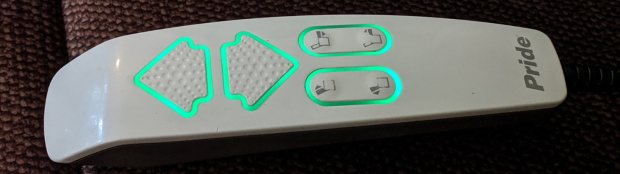
The green LED-lit buttons were so bright I took it apart to see what could be done; the picture shows the considerably dimmed result.
Start by prying outward on the tab at the USB charging port:
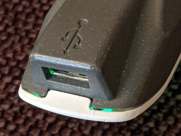
Done right, you can then release the latches along the sides:
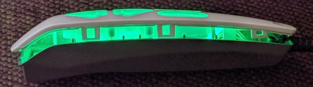
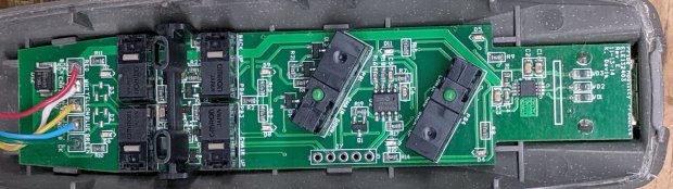
It’s impossible to photograph the PCB with the LEDs active, but here’s what it looks like without power:
The eight (!) SMD LEDs align with light pipes around the switch openings:
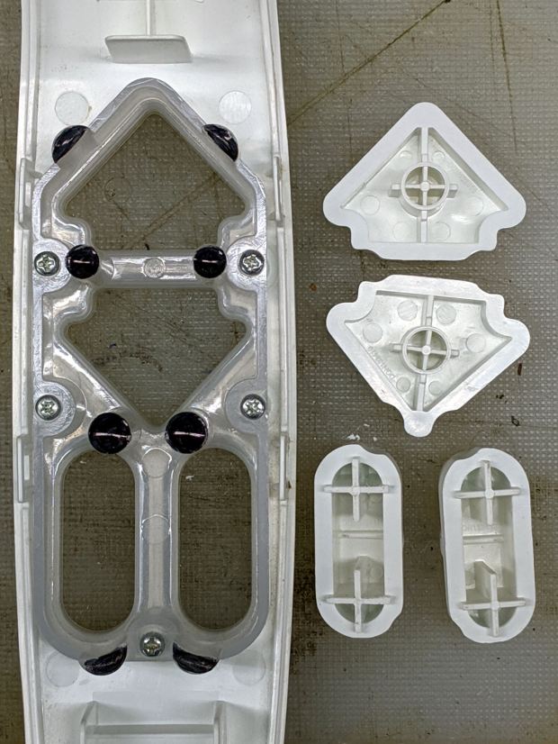
The black dots come from Sharpie ink daubed in the shallow recesses intended to nestle around the LEDs. Note that the four switch caps have unique keying, so you can’t put them back incorrectly without some effort.
While we’re inside, here’s a closer look at the cable entry point, just in case I must replace the industrial-strength coily cord:
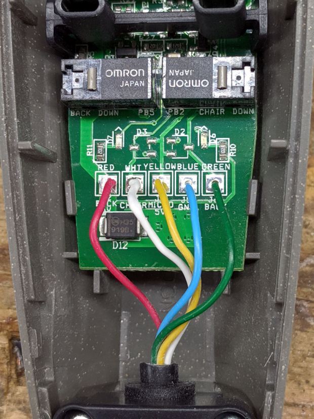
Unfortunately, it has a five-conductor cable, so a cheap phone coily cord (remember when phones had coily cords?) won’t suffice.
The PCB sports a pair of PICs, one of which seems to handle the buttons. I betcha the cable dates back to the days of hard-wired power switches, with the PIC now handling the intricate logic of deciding which motors to actuate for each function, then controlling MOSFETs as fake switch contacts.
The other PIC snuggles against the USB interface, which the manual describes as a charging-only port. It might also serve as a programming interface for the main PIC; admittedly the notion of a firmware upgrade for a lift chair seems far-fetched.
Reassembly is in reverse order with a resounding snap at the conclusion. It works fine and you (well, I) can now look at the control pod without sunglasses.
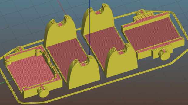
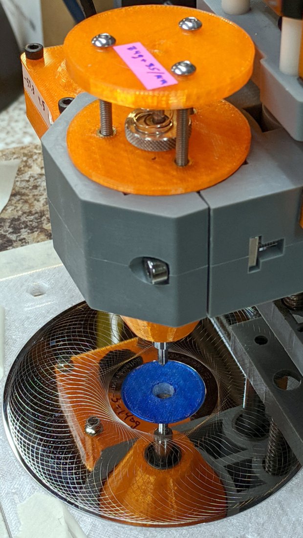
I actually had this in mind when I laid out the hard drive and CD engraving fixtures:

The fixtures are centered at X±70.0 mm / Y=0.0 from the G54 workspace coordinate origin dead-center in the middle of the platform, with G55 centered on the HD fixture to the left and G56 on the CD fixture to the right.
So the engraving workflow amounts to homing the CNC 3018 when I turn it on, taping a platter in a fixture, selecting the corresponding WCS, loading a suitable G-Code file, and firing it off. It seems bCNC returns to G54 after completing the file, so verifying the WCS selection every time is Very Good Practice.
The friable lacquer coating on some CDs fills my world with glitter whenever I engrave a pattern on their label side. I didn’t plan on a dust shoe for this thing!
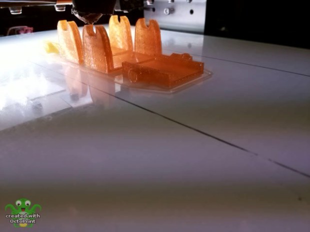
Octopirint / Octopi works wonderfully well as a controller / G-Code feeder for my Makergear M2. After putting up with an ungainly mass of tape for far too long, I printed Toddman’s Pi Camera Mount:
Which snapped together exactly like it should:
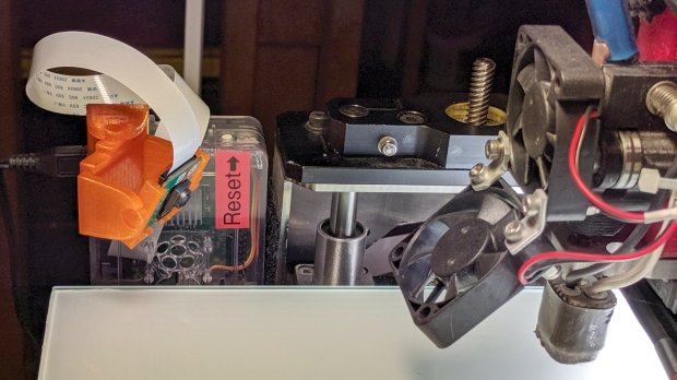
A strip of double-sided foam tape attaches it to the Pi’s case, which is Velcro-ed to the M2’s frame. The cable may be too long, but avoids sharp bends on the way out of the case.
The whole lashup works fine:
That’s a second set intended for the CNC 3018-Pro, but it didn’t fit quite as well. The B brackets are slightly too long (or their pivots are slightly too close to their base) to allow the C plates to turn 90° to the mount:

Nothing one can’t fix with nibbling & filing, but I long for parametric designs …
I got an Alead / Nolan HearLinks (many adjectives) Telecoil receiver to boost my ability to hear music & presentations at Vassar, because they recently slotted telecoil loops into the floors of their public venues. It took a few concerts to get the appropriate volume setting, after which I wondered how sensitive the receiver was:

The small T in the upper right corner marks the receiving coil location, with the coil oriented parallel to the body’s long axis. It’s the secondary winding of an air-core transformer with a single-turn (perhaps using Litz wire) primary embedded in the floor, with the induced voltage obeying the usual transformer equation:
V = 2π µ₀ µr N A f H cos θDefinitions:
For a given installation and receiver position, pretty much everything is fixed, with the voltage depending only on the H field caused by the primary winding current.
The induced voltage is linearly dependent on the frequency, but the transmitter equalization filters apparently flatten the spectrum to get equal receiver amplitude between about 100 Hz and 5 kHz.
The coil in that picture has nine turns, with four passing through the Tek current probe. Applying 10 mVpp to the winding produces a corresponding current:

The scope sees 14 mVpp = 1.4 div at 1 mA/div = 1.4 mA. Dividing by 4 turns means the coil actually carryes 350 µA. The signal generator has a 50 Ω output impedance, so 10 mV should produce about 200 µA, which seems a bit low. On the other paw, the signal generator sees the coil as a dead short at 1 kHz, so I don’t trust the numbers.
Whatever magnetic flux it may be produces a 1 kHz tone at a somewhat higher volume (for the same receiver setting) than the fancy Vassar loops, so the flux is in the right ballpark. With a bit more attention to detail, perhaps I can tinker up a current-mode loop drive amplifier.
The Alead receiver has an internally generated tick audible at the audio volume I need for the Vassar loops, which is 5 to 7 steps down from the maximum volume at 15 steps. It seems related to the internal Bluetooth hardware, although it’s present even when the receiver is not paired with my Pixel phone and, in fact, is unchanged even when 100 feet from the nearest electronic device.
When I reported the problem, they said:
Yes, you can hear very minor tick sound on telecoil mode. It is caused by some electronic and current to make those tick sound. Sorry for this defective on the design.
It had one job that it doesn’t do well, so it’s on the way back for a refund.
Evidently, I must build an audio loop receiver to get what I want …
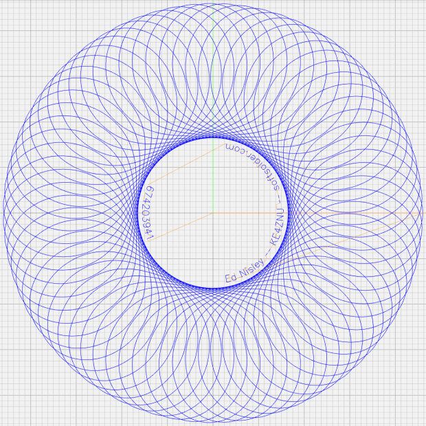
Engraving Spirograph / Guilloché patterns on scrap CDs and hard drive platters now works better than ever:
After, that is, I realized:
One of my final doodles showing how the variables relate to each other, although the Wikipedia article may be useful for the underlying math and other posts have more pix on various machines:
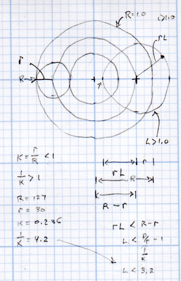
Cheat sheet:
Picking a suitable rotor requires iterating with random choices until one fits:
  RotorTeeth = Stators[-1];
  n = 0;
  while (RotorTeeth >= floor(0.95 * StatorTeeth) || RotorTeeth < 5) {
    RotorTeeth = (XORshift() & 0x007f);       // this is why Stator can't have more than 127 teeth
    n++;
  }
  comment("Rotor: ",RotorTeeth," in ",n," iterations");
The 5% buffer on the high end ensures there will be an L keeping a hole in the middle of the pattern. Requiring at least five teeth on the low end just seems like a Good Idea.
Given the stator & rotor tooth counts, iterate on random L values until one works:
  n = 0;
  do {
    L = (to_float((XORshift() & 0x1f) + 1) / 32.0) * (1.0/K - 1.0);   // allow L > 1.0
    n++;
  } while (L >= (1.0/K - 1.0) || L < 0.01);
}
comment("Offset L: ", L," in ",n," iterations");
With L chosen to leave a hole in the middle of the pattern, then the pattern traced by the pen in the rotor is centered at 1.0 – K (the normalized Stator radius minus the normalized Rotor radius) and varies by ±LK (the offset times the normalized Rotor radius) on either side:
RotorMin = 1.0 - 2*K;
comment("Rotor Min: ",RotorMin);

BandCtr = 1.0 - K;                      // band center radius
BandMin = BandCtr - L*K;                //  ... min radius
BandMax = BandCtr + L*K;                //  ... max radius

BandAmpl = BandMax - BandCtr;

comment("Band Min: ",BandMin," Ctr: ",BandCtr," Max: ",BandMax);
Knowing that, rescaling the pattern to fit the disk limits goes like this:
FillPath = {};

foreach (Path; pt) {

  a = atan_xy(pt);                      // recover angle to point
  r = length(pt);                       //  ... radius to point

  br = (r - BandCtr) / BandAmpl;        // remove center bias, rescale to 1.0 amplitude
  dr = br * (OuterRad - MidRad);        // rescale to fill disk
  pr = dr + MidRad;                     // set at disk centerline

  x = pr * cos(a);                      // find new XY coords
  y = pr * sin(a);

  FillPath += {[x,y]};
}

comment("Path has ",count(FillPath)," points");
The final step prunes coordinates so close together as to produce no useful motion, which I define to be 0.2 mm:
PointList = {FillPath[0]};                // must include first point

lp = FillPath[0];
n = 0;

foreach (FillPath; pt) {
  if (length(pt - lp) <= Snuggly) {       // discard too-snuggly point
    n++;
  }
  else {
    PointList += {pt};                    // otherwise, add it to output
    lp = pt;
  }
}

PointList += {FillPath[-1]};                // ensure closure at last point

comment("Pruned ",n," points, ",count(PointList)," remaining");
The top of the resulting G-Code file contains all the various settings for debugging:
(Disk type: CD)
(Outer Diameter: 117.000mm)
(        Radius: 58.500mm)
(Inner Diameter: 38.000mm)
(        Radius: 19.000mm)
(Mid Diameter: 77.500mm)
(      Radius: 38.750mm)
(Legend Diameter: 30.000mm)
(         Radius: 15.000mm)
(PRNG seed: 674203941)
(Stator 8: 71)
(Rotor: 12 in 1 iterations)
(Dia ratio K: 0.169 1/K: 5.917)
(GCD: 1)
(Lobes: 71)
(Turns: 12)
(Offset L: 3.227 in 1 iterations)
(Rotor Min: 0.662)
(Band Min: 0.286 Ctr: 0.831 Max: 1.376)
(Path has 43201 points)
(Pruned 14235 points, 28968 remaining)
The GCMC source code as a GitHub Gist:
| // Spirograph simulator for MPCNC used as plotter | |
| // Ed Nisley KE4ZNU – 2017-12-23 | |
| // Adapted for Guillioche plots with ball point pens – 2018-09-25 | |
| // 2019-06 Text on circular arcs | |
| // 2019-08 Coordinate pruning | |
| // 2019-09 Allow L > 1.0, proper scale to fit disk | |
| // Spirograph equations: | |
| // https://en.wikipedia.org/wiki/Spirograph | |
| // Loosely based on GCMC cycloids.gcmc demo: | |
| // https://gitlab.com/gcmc/gcmc/tree/master/example/cycloids.gcmc | |
| //—– | |
| // Library routines | |
| include("tracepath.inc.gcmc"); | |
| include("engrave.inc.gcmc"); | |
| //—– | |
| // Define useful constants | |
| SafeZ = 10.00mm; | |
| TravelZ = 1.00mm; | |
| AngleStep = 0.1deg; | |
| Snuggly = 0.2mm; // prune coordinates when closer | |
| TextFont = FONT_HSANS_1_RS; | |
| TextSize = [1.5mm,1.5mm]; | |
| //—– | |
| // Command line parameters | |
| // -D DiskType="string" | |
| if (!isdefined("DiskType")) { | |
| DiskType = "CD"; | |
| } | |
| if (DiskType != "CD" && // list all possible types | |
| DiskType != "3.5" && | |
| DiskType != "TrimCD" | |
| ) { | |
| error("Unknown disk type: ",DiskType); | |
| } | |
| comment("Disk type: ",DiskType); // default is "CD" | |
| Margin = 1.5mm; // clamping margin around disk OD | |
| DiskDia = (DiskType == "3.5") ? 95.0mm : | |
| (DiskType == "TrimCD") ? 95.0mm : | |
| 120.0mm; | |
| OuterDia = DiskDia – 2*Margin; | |
| OuterRad = OuterDia / 2; | |
| comment("Outer Diameter: ",OuterDia); | |
| comment(" Radius: ",OuterRad); | |
| InnerDia = (DiskType == "3.5") ? 33.0mm : | |
| (DiskType == "TrimCD") ? 38.0mm : | |
| 38.0mm; | |
| InnerDia = InnerDia; | |
| InnerRad = InnerDia / 2; | |
| comment("Inner Diameter: ",InnerDia); | |
| comment(" Radius: ",InnerRad); | |
| MidDia = (InnerDia + OuterDia) / 2; | |
| MidRad = MidDia / 2; | |
| comment("Mid Diameter: ",MidDia); | |
| comment(" Radius: ",MidRad); | |
| LegendDia = (DiskType == "3.5") ? 31.0mm : | |
| (DiskType == "TrimCD") ? 31.0mm : | |
| 30.0mm; | |
| LegendDia = LegendDia; | |
| LegenRad = LegendDia / 2; | |
| comment("Legend Diameter: ",LegendDia); | |
| comment(" Radius: ",LegenRad); | |
| // -D PRNG_Seed=integer non-zero random number seed | |
| if (isdefined("PRNG_Seed")) { // did we get a seed? | |
| if (!PRNG_Seed) { // .. it must not be zero | |
| PRNG_Seed = 347221084; | |
| } | |
| } | |
| else { // no incoming seed, so use a constant | |
| PRNG_Seed = 674203941; | |
| } | |
| comment("PRNG seed: ",PRNG_Seed); | |
| PRNG_State = PRNG_Seed; // set initial state | |
| // -D various other useful tidbits | |
| // add unit to speeds and depths: 2000mm / -3.00mm / etc | |
| if (!isdefined("PlotSpeed")) { | |
| PlotSpeed = 2400mm; | |
| } | |
| if (!isdefined("TextSpeed")) { | |
| TextSpeed = 2000mm; | |
| } | |
| // Force is proportional to depth, but you must know the coefficent! | |
| if (!isdefined("PlotZ")) { | |
| PlotZ = (DiskType == "3.5") ? -3.00 : -0.25mm; | |
| } | |
| if (!isdefined("Legend")) { | |
| Legend = "Ed Nisley – KE4ZNU – softsolder.com"; | |
| } | |
| //—– | |
| // Spirograph tooth counts mooched from: | |
| // http://nathanfriend.io/inspirograph/ | |
| // Stators includes both inside and outside counts, because we're not fussy | |
| // Stator with prime tooth count will always produce that number of lobes | |
| // Prime numbers: | |
| // https://en.wikipedia.org/wiki/Prime_number | |
| // Table of primes: | |
| // https://www.factmonster.com/math/numbers/prime-numbers-facts-examples-table-all-1000 | |
| // Must be sorted and should not exceed 127 teeth, which will make plenty of lobes | |
| Stators = [37,41,43,47,53,59,61,67,71,73,79,83,89,97,101,103,107,109,113,127]; | |
| // Rotor tooth count chosen randomly, these are for the old method | |
| Rotors = [24, 30, 32, 36, 40, 45, 48, 50, 52, 56, 60, 63, 64, 72, 75, 80, 84]; | |
| //Rotors = [5,7,11,13,17,19,23,31,37,41,47]; | |
| //—– | |
| // Greatest Common Divisor | |
| // https://en.wikipedia.org/wiki/Greatest_common_divisor#Using_Euclid's_algorithm | |
| // Inputs = integers without units | |
| // This is unused with prime rotor tooth counts left here for completeness | |
| function gcd(a,b) { | |
| if (!isnone(a) || isfloat(a) || !isnone(b) || isfloat(b)) { | |
| error("GCD params must be dimensionless integers. a: ",a," b: ",b); | |
| } | |
| local d = 0; // power-of-two counter | |
| while (!((a | b) & 1)) { // remove and tally common factors of two | |
| a >>= 1; | |
| b >>= 1; | |
| d++; | |
| } | |
| while (a != b) { | |
| if (!(a & 1)) {a >>= 1;} // discard non-common factor of 2 | |
| elif (!(b & 1)) {b >>= 1;} // … likewise | |
| elif (a > b) {a = (a – b) >> 1;} // gcd(a,b) also divides a-b | |
| else {b = (b – a) >> 1;} // … likewise | |
| } | |
| local GCD = a*(1 << d); // form gcd | |
| // message("GCD: ",GCD); | |
| return GCD; | |
| } | |
| //—– | |
| // Max and min functions | |
| function max(x,y) { | |
| return (x > y) ? x : y; | |
| } | |
| function min(x,y) { | |
| return (x < y) ? x : y; | |
| } | |
| //—– | |
| // Pseudo-random number generator | |
| // Based on xorshift: | |
| // https://en.wikipedia.org/wiki/Xorshift | |
| // http://www.jstatsoft.org/v08/i14/paper | |
| // Requires initial state from calling script | |
| // -D "PRNG_Seed=whatever" | |
| // Bash (et. al.) supplies nine reasonably random digits from $(date +%N) | |
| function XORshift() { | |
| local x = PRNG_State; // fetch current state | |
| x ^= x << 13; | |
| x ^= x >> 17; | |
| x ^= x << 5; | |
| PRNG_State = x; // save state for next invocation | |
| return x; | |
| } | |
| //—– | |
| // Bend text around an arc | |
| function ArcText(TextPath,Center,Radius,BaseAngle,Align) { | |
| PathLength = TextPath[-1].x; | |
| Circumf = 2*pi()*Radius; | |
| TextAngle = to_deg(360 * PathLength / Circumf); | |
| AlignAngle = BaseAngle + (Align == "Left" ? 0 : | |
| Align == "Center" ? -TextAngle / 2 : | |
| Align == "Right" ? -TextAngle : | |
| 0); | |
| ArcPath = {}; | |
| foreach(TextPath; pt) { | |
| if (!isundef(pt.x) && !isundef(pt.y) && isundef(pt.z)) { // XY motion, no Z | |
| r = Radius – pt.y; | |
| a = 360deg * (pt.x / Circumf) + AlignAngle; | |
| ArcPath += {[r*cos(a) + Center.x, r*sin(a) + Center.y,-]}; | |
| } | |
| elif (isundef(pt.x) && isundef(pt.y) && !isundef(pt.z)) { // no XY, Z up/down | |
| ArcPath += {pt}; | |
| } | |
| else { | |
| error("Point is not pure XY or pure Z: " + to_string(pt)); | |
| } | |
| } | |
| return ArcPath; | |
| } | |
| //—– | |
| // Set up gearing | |
| s = (XORshift() & 0xffff) % count(Stators); | |
| StatorTeeth = Stators[s]; | |
| comment("Stator ",s,": ",StatorTeeth); | |
| // When Stator has prime teeth, any Rotor will have GCD = 1 | |
| if (1) { | |
| RotorTeeth = Stators[-1]; | |
| n = 0; | |
| while (RotorTeeth >= floor(0.95 * StatorTeeth) || RotorTeeth < 5) { | |
| RotorTeeth = (XORshift() & 0x007f); // this is why Stator can't have more than 127 teeth | |
| n++; | |
| } | |
| comment("Rotor: ",RotorTeeth," in ",n," iterations"); | |
| } | |
| else { | |
| r = (XORshift() & 0xffff) % count(Rotors); | |
| RotorTeeth = Rotors[r]; | |
| comment("Rotor ",r,": ",RotorTeeth); | |
| } | |
| K = to_float(RotorTeeth) / to_float(StatorTeeth); // find normalized rotor dia | |
| comment("Dia ratio K: ",K," 1/K: ",1.0/K); | |
| GCD = gcd(StatorTeeth,RotorTeeth); // reduce teeth to ratio of least integers | |
| comment("GCD: ",GCD); | |
| Lobes = StatorTeeth / GCD; // compute useful values | |
| comment("Lobes: ", Lobes); | |
| Turns = RotorTeeth / GCD; | |
| comment("Turns: ", Turns); | |
| // Find normalized pen offset to never cross Stator center | |
| if (1) { | |
| n = 0; | |
| do { | |
| L = (to_float((XORshift() & 0x1f) + 1) / 32.0) * (1.0/K – 1.0); // allow L > 1.0 | |
| // comment(" test L: ",L); | |
| n++; | |
| } while (L >= (1.0/K – 1.0) || L < 0.01); | |
| } | |
| else { | |
| n = 0; | |
| do { | |
| L = to_float((XORshift() & 0x1f) + 1) / 32.0; // force L < 1.0 | |
| n++; | |
| } while (L >= (1.0/K – 1.0) || L < 0.01); | |
| } | |
| comment("Offset L: ", L," in ",n," iterations"); | |
| //—– | |
| // Crank out a list of points in normalized coordinates | |
| Path = {}; | |
| for (a = 0.0deg ; a <= Turns*360deg ; a += AngleStep) { | |
| x = (1 – K)*cos(a) + L*K*cos(a*(1 – K)/K); | |
| y = (1 – K)*sin(a) – L*K*sin(a*(1 – K)/K); | |
| Path += {[x,y]}; | |
| } | |
| //—– | |
| // Calculate normalized limits for band traced by pen in rotor at offset L | |
| // L was chosen to produce a band around the rotor center point | |
| RotorMin = 1.0 – 2*K; | |
| comment("Rotor Min: ",RotorMin); | |
| BandCtr = 1.0 – K; // band center radius | |
| BandMin = BandCtr – L*K; // … min radius | |
| BandMax = BandCtr + L*K; // … max radius | |
| BandAmpl = BandMax – BandCtr; | |
| comment("Band Min: ",BandMin," Ctr: ",BandCtr," Max: ",BandMax); | |
| //—– | |
| // Scale normalized band to fill physical limits centered at mid-disk radius | |
| FillPath = {}; | |
| foreach (Path; pt) { | |
| a = atan_xy(pt); // recover angle to point | |
| r = length(pt); // … radius to point | |
| br = (r – BandCtr) / BandAmpl; // remove center bias, rescale to 1.0 amplitude | |
| dr = br * (OuterRad – MidRad); // rescale to fill disk | |
| pr = dr + MidRad; // set at disk centerline | |
| x = pr * cos(a); // find new XY coords | |
| y = pr * sin(a); | |
| FillPath += {[x,y]}; | |
| } | |
| comment("Path has ",count(FillPath)," points"); | |
| //—– | |
| // Prune too-snuggly physical coordinates | |
| PointList = {FillPath[0]}; // must include first point | |
| lp = FillPath[0]; | |
| n = 0; | |
| foreach (FillPath; pt) { | |
| if (length(pt – lp) <= Snuggly) { // discard too-snuggly point | |
| n++; | |
| } | |
| else { | |
| PointList += {pt}; // otherwise, add it to output | |
| lp = pt; | |
| } | |
| } | |
| PointList += {FillPath[-1]}; // ensure closure at last point | |
| comment("Pruned ",n," points, ",count(PointList)," remaining"); | |
| //—– | |
| // Convert coordinate list to G-Code | |
| comment("Pattern begins"); | |
| feedrate(PlotSpeed); | |
| goto([-,-,SafeZ]); | |
| goto([0,0,-]); | |
| goto([-,-,TravelZ]); | |
| tracepath(PointList, PlotZ); | |
| //—– | |
| // Draw the legend | |
| comment("Legend begins"); | |
| if (Legend) { | |
| tp = scale(typeset(Legend,TextFont),TextSize); | |
| tpa = ArcText(tp,[0mm,0mm],LegenRad,0deg,"Center"); | |
| feedrate(TextSpeed); | |
| engrave(tpa,TravelZ,PlotZ); | |
| } | |
| tp = scale(typeset(to_string(PRNG_Seed),TextFont),TextSize); | |
| tpa = ArcText(tp,[0mm,0mm],LegenRad,180deg,"Center"); | |
| feedrate(TextSpeed); | |
| engrave(tpa,TravelZ,PlotZ); | |
| goto([-,-,SafeZ]); // done, so get out of the way | |
| goto([0,0,-]); | |
| comment("Disk ends"); |
| #!/bin/bash | |
| # Guilloche and Legend Generator | |
| # Ed Nisley KE4ZNU – 2019-06 | |
| Disk='DiskType="CD"' | |
| PlotZ='PlotZ=-3.00mm' | |
| Legend='Legend="Ed Nisley — KE4ZNU — softsolder.com"' | |
| Flags='-P 3 –pedantic' | |
| # Set these to match your file layout | |
| LibPath='/opt/gcmc/library' | |
| Prolog='/mnt/bulkdata/Project Files/CNC 3018-Pro Router/Patterns/gcmc/prolog.gcmc' | |
| Epilog='/mnt/bulkdata/Project Files/CNC 3018-Pro Router/Patterns/gcmc/epilog.gcmc' | |
| Script='/mnt/bulkdata/Project Files/CNC 3018-Pro Router/Patterns/Platter Engraving.gcmc' | |
| ts=$(date +%Y%m%d-%H%M%S) | |
| if [ -n "$1" ] # if random seed parameter exists | |
| then | |
| rnd=$1 # .. use it | |
| else | |
| rnd=$(date +%N) # .. otherwise use nanoseconds | |
| fi | |
| fn="Disk_${ts}_${rnd}.ngc" | |
| echo Output: $fn | |
| Seed="PRNG_Seed=$rnd" | |
| rm -f $fn | |
| echo "(File: "$fn")" > $fn | |
| gcmc -D "$Disk" -D "$Seed" -D "$Legend" -D "$PlotZ" $Flags \ | |
| –include "$LibPath" –prologue "$Prolog" –epilogue "$Epilog" \ | |
| "$Script" >> "$fn" | |
A variation on the CD fixture produces a 3.5 inch hard drive platter fixture:
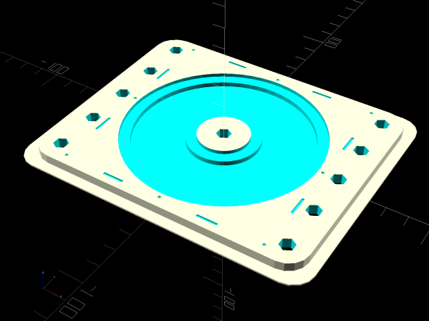
Which needed just a touch of milling for a snug fit around the platter:

Tape it down on the 3018’s platform, set XY=0 at the center, and It Just Works™:

The rather faint line shows engraving at -1.0 mm = 70 g downforce isn’t quite enough. Another test with the same pattern at -3.0 mm = 140 g came out better:
It’s in the same OpenSCAD file as the CD fixture, in the unlikely event you need one.
