|
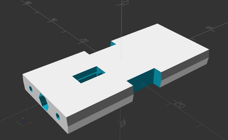
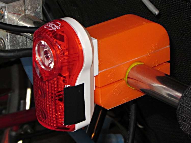
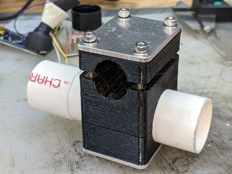
// Rear running light clamp for Tour Easy seat strut |
|
// Ed Nisley – KE4ZNU – 2021-09 |
|
|
|
Layout = "Show"; // [Show,Build,Block] |
|
|
|
Section = true; |
|
|
|
/* [Hidden] */ |
|
|
|
ThreadThick = 0.25; |
|
ThreadWidth = 0.40; |
|
|
|
HoleWindage = 0.2; |
|
|
|
Protrusion = 0.1; // make holes end cleanly |
|
|
|
function IntegerMultiple(Size,Unit) = Unit * ceil(Size / Unit); |
|
|
|
ID = 0; |
|
OD = 1; |
|
LENGTH = 2; |
|
|
|
inch = 25.4; |
|
|
|
//———————- |
|
// Dimensions |
|
// Light case along X axis, seat strut along Y, Z=0 at strut centerline |
|
|
|
LightOD = 25.4 + HoleWindage; |
|
|
|
StrutOD = 5/8 * inch + HoleWindage; |
|
|
|
PlateThick = 1/16 * inch; |
|
|
|
WallThick = 2.0; |
|
|
|
Kerf = ThreadThick; |
|
|
|
Screw = [3.0,6.8,4.0]; // M3 OD=washer, length=nut + washers |
|
Insert = [3.0,5.4,8.0 + 1.0]; // splined brass insert |
|
|
|
RoundRadius = IntegerMultiple(Screw[OD]/2,0.5); // corner rounding |
|
|
|
ScrewOC = [IntegerMultiple(StrutOD + 2*WallThick + Screw[ID],1.0), |
|
IntegerMultiple(LightOD + 2*WallThick + Screw[ID],1.0)]; |
|
|
|
echo(str("Screw OC: ",ScrewOC)); |
|
|
|
BlockSize = [ScrewOC.x + Insert[OD] + 2*WallThick, |
|
ScrewOC.y + Insert[OD] + 2*WallThick, |
|
LightOD + StrutOD + 3*WallThick]; |
|
|
|
echo(str("Block: ",BlockSize)); |
|
|
|
BaseOffset = -(WallThick + LightOD/2); // block bottom to centerline |
|
StrutOffset = LightOD/2 + WallThick + StrutOD/2; // light centerline to strut centerline |
|
|
|
echo(str("Strut screw min: ",IntegerMultiple(PlateThick + WallThick + StrutOD/2 + Insert[LENGTH]/2,1.0))); |
|
echo(str("Light screw min: ",IntegerMultiple(PlateThick + WallThick + LightOD/2 + Insert[LENGTH]/2,1.0))); |
|
|
|
NumSides = 2*3*4; |
|
|
|
//———————- |
|
// Useful routines |
|
|
|
module PolyCyl(Dia,Height,ForceSides=0) { // based on nophead's polyholes |
|
|
|
Sides = (ForceSides != 0) ? ForceSides : (ceil(Dia) + 2); |
|
FixDia = Dia / cos(180/Sides); |
|
cylinder(r=(FixDia + HoleWindage)/2, |
|
h=Height, |
|
$fn=Sides); |
|
} |
|
|
|
// Block with light along X axis |
|
|
|
module Block() { |
|
|
|
difference() { |
|
hull() |
|
for (i=[-1,1], j=[-1,1]) |
|
translate([i*(BlockSize.x/2 – RoundRadius),j*(BlockSize.y/2 – RoundRadius),BaseOffset]) |
|
cylinder(r=RoundRadius,h=BlockSize.z,$fn=NumSides); |
|
|
|
for (i=[-1,1], j=[-1,1]) |
|
translate([i*ScrewOC.x/2,j*ScrewOC.y/2,BaseOffset – Protrusion]) |
|
rotate(180/8) |
|
PolyCyl(Screw[ID],BlockSize.z + 2*Protrusion,8); |
|
|
|
for (i=[-1,1], j=[-1,1]) |
|
translate([i*ScrewOC.x/2,j*ScrewOC.y/2,0]) { |
|
translate([0,0,-Protrusion]) |
|
rotate(180/8) |
|
PolyCyl(Insert[OD],Insert[LENGTH] + 1*Protrusion,8); |
|
translate([0,0,(StrutOffset – Insert[LENGTH] – Kerf/2 + Protrusion)]) |
|
rotate(180/8) |
|
PolyCyl(Insert[OD],Insert[LENGTH] + 1*Protrusion,8); |
|
} |
|
|
|
translate([-BlockSize.x,0,0]) |
|
rotate([0,90,0]) |
|
cylinder(d=LightOD,h=2*BlockSize.x,$fn=NumSides); |
|
|
|
translate([0,BlockSize.y,StrutOffset]) |
|
rotate([90,0,0]) |
|
cylinder(d=StrutOD,h=2*BlockSize.y,$fn=NumSides); |
|
|
|
translate([0,0,StrutOffset]) |
|
cube([2*BlockSize.x,2*BlockSize.y,Kerf],center=true); |
|
|
|
cube([2*BlockSize.x,2*BlockSize.y,Kerf],center=true); |
|
|
|
} |
|
|
|
} |
|
|
|
|
|
//- Build it |
|
|
|
if (Layout == "Block") |
|
if (Section) |
|
difference() { |
|
Block(); |
|
rotate(atan(ScrewOC.y/ScrewOC.x)) |
|
translate([0,BlockSize.y,0]) |
|
cube(2*BlockSize,center=true); |
|
} |
|
else |
|
Block(); |
|
|
|
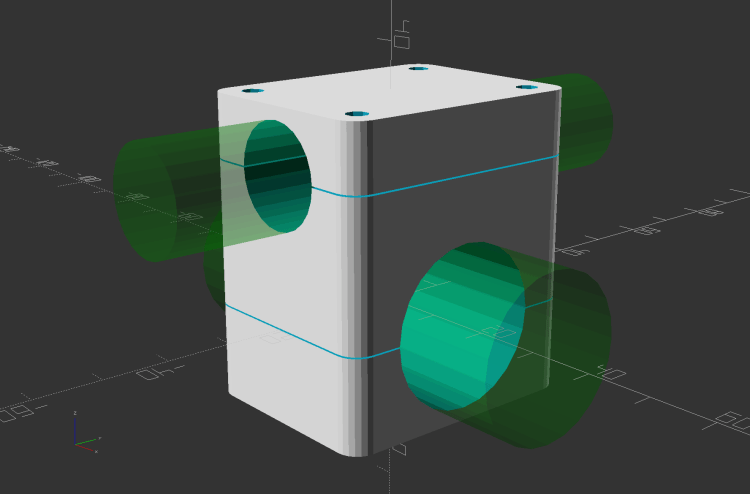
if (Layout == "Show") { |
|
Block(); |
|
|
|
color("Green",0.25) |
|
translate([-BlockSize.x,0,0]) |
|
rotate([0,90,0]) |
|
cylinder(d=LightOD,h=2*BlockSize.x,$fn=NumSides); |
|
|
|
color("Green",0.25) |
|
translate([0,BlockSize.y,StrutOffset]) |
|
rotate([90,0,0]) |
|
cylinder(d=StrutOD,h=2*BlockSize.y,$fn=NumSides); |
|
} |
|
|
|
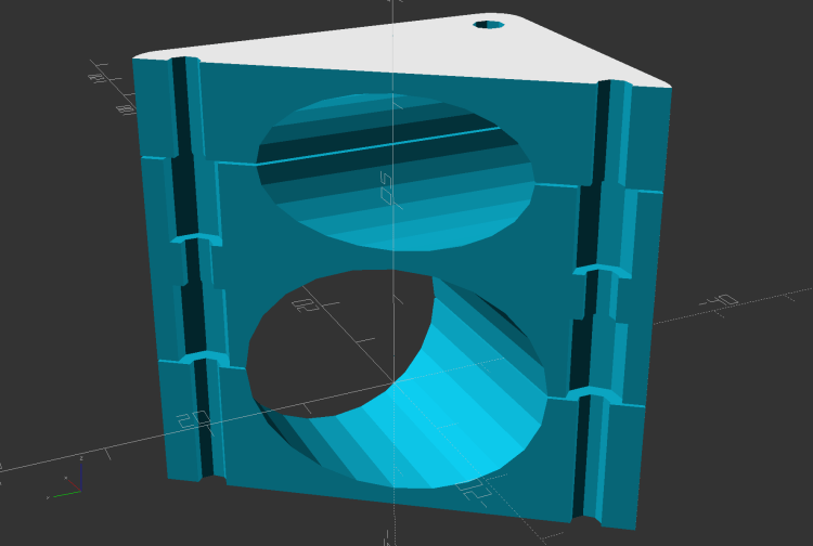
if (Layout == "Build") { |
|
translate([-1.2*BlockSize.x,0,-BaseOffset]) |
|
difference() { |
|
Block(); |
|
translate([0,0,BlockSize.z]) |
|
cube(2*BlockSize,center=true); |
|
} |
|
|
|
translate([1.2*BlockSize.x,0,StrutOD/2 + WallThick]) |
|
difference() { |
|
rotate([180,0,0]) |
|
translate([0,0,-StrutOffset]) |
|
Block(); |
|
translate([0,0,BlockSize.z]) |
|
cube(2*BlockSize,center=true); |
|
} |
|
|
|
translate([0,0,StrutOffset – Kerf/2]) |
|
rotate([180,0,0]) |
|
intersection() { |
|
Block(); |
|
translate([0,0,StrutOffset/2]) |
|
cube([2*BlockSize.x,2*BlockSize.y,StrutOffset],center=true); |
|
} |
|
} |