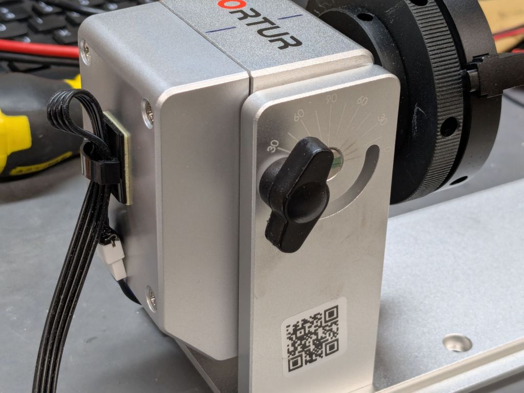
Although the Ortur YRC-1 chuck rotary comes with a long cable, the connector doesn’t match anything in my heap, so an adapter of some sort was in order. The box includes three different adapters for various machines, none of which I have, but which served as raw material.
One of the adapters put the motor winding pairs together, which seemed like a Good Idea™:
That view has the stepper motor flipped 180° from its normal orientation; the motor cable connector normally points downward from the bottom.
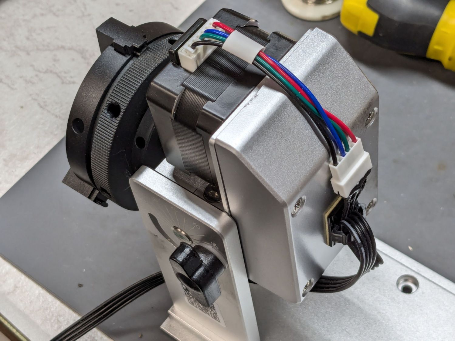
The rotary has no strain relief for the cable, so I stuck a cable clip on its left side (in the normal orientation):

That arrangement captures the adapter, immobilizes the wiring at the motor, and puts all the strain on the more easily replaced cable, which is now a length of flexy 24 AWG silicone ribbon cable.
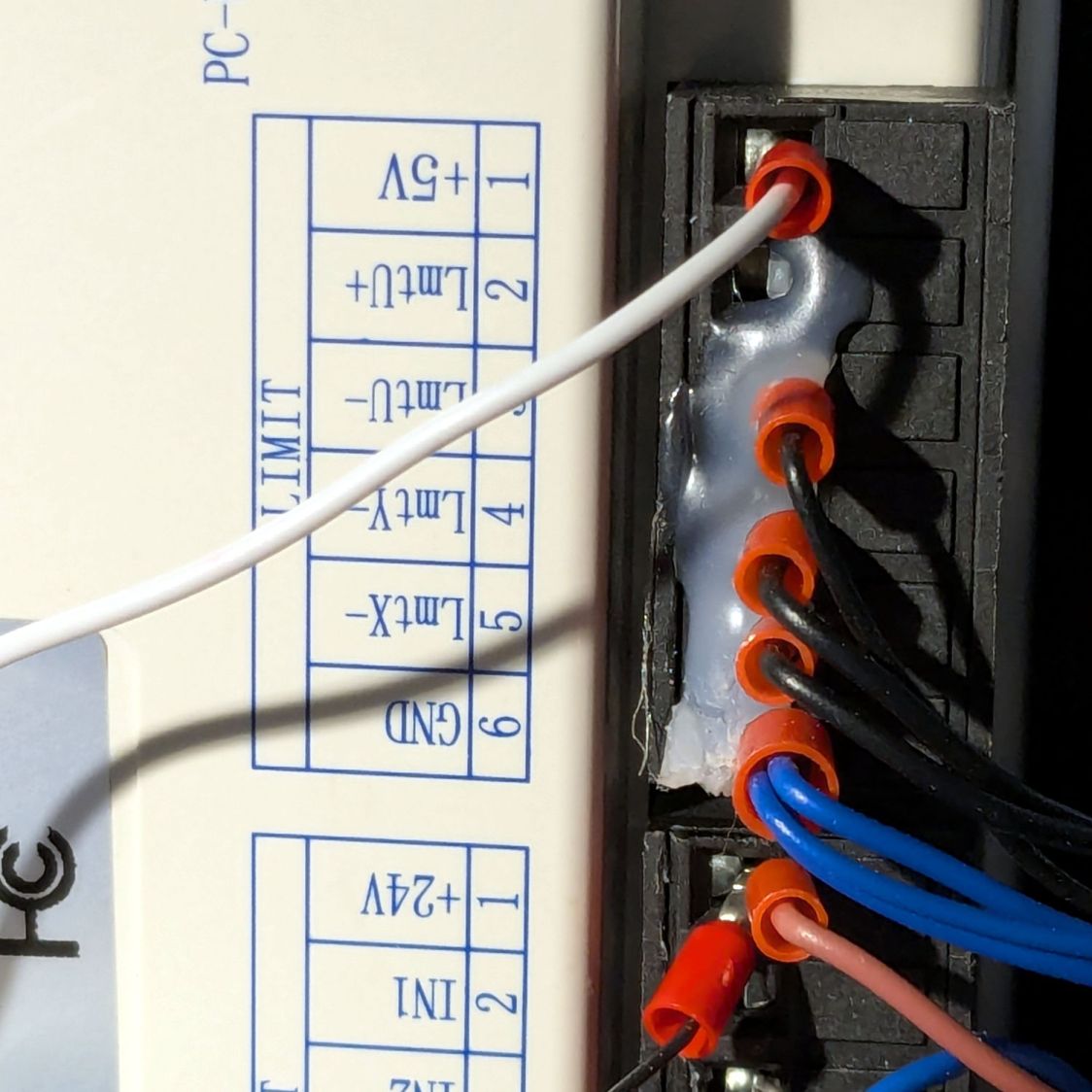
I don’t have a connector matching the Ortur adapter, but JST SM pins seemed about the right size:

Entombing that mess with a squirt of hot melt glue should keep them out of trouble.
You can see my matching JST SM connectors on the right end of the ribbon cable :
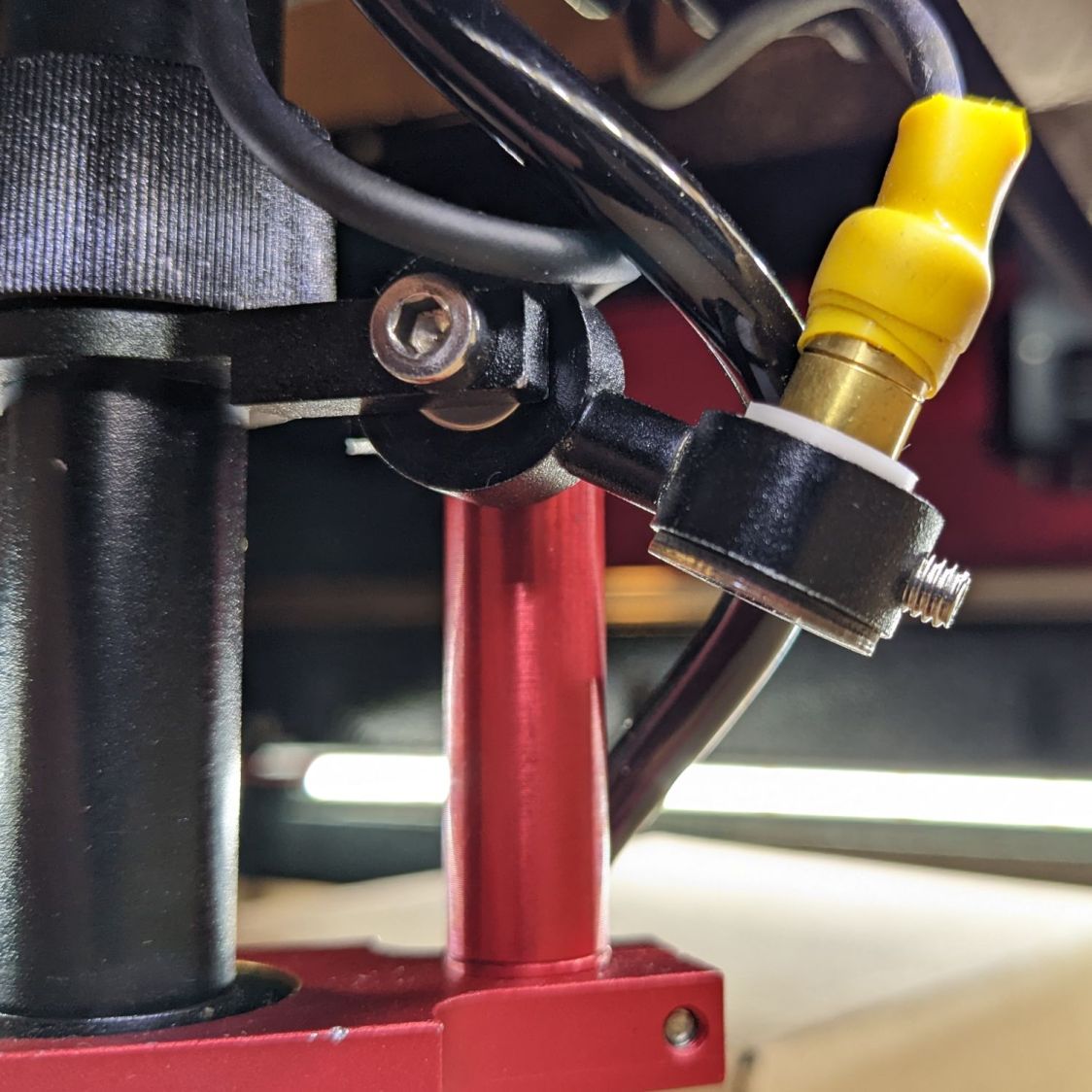
A cable clip stuck to the front cross member of the machine frame (just beyond the angled magnet) holds the unplugged end out of harm’s way when the rotary isn’t present.
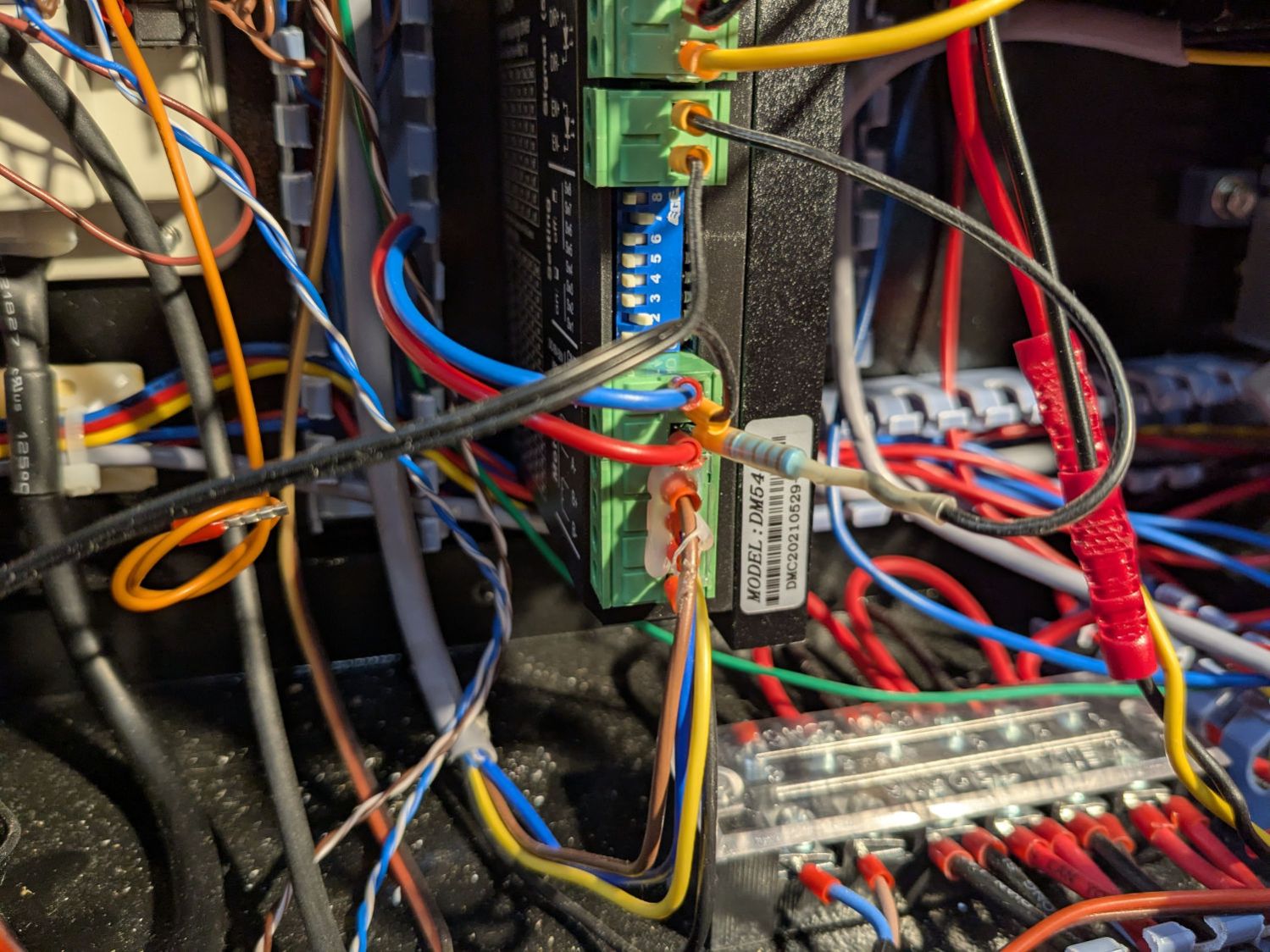
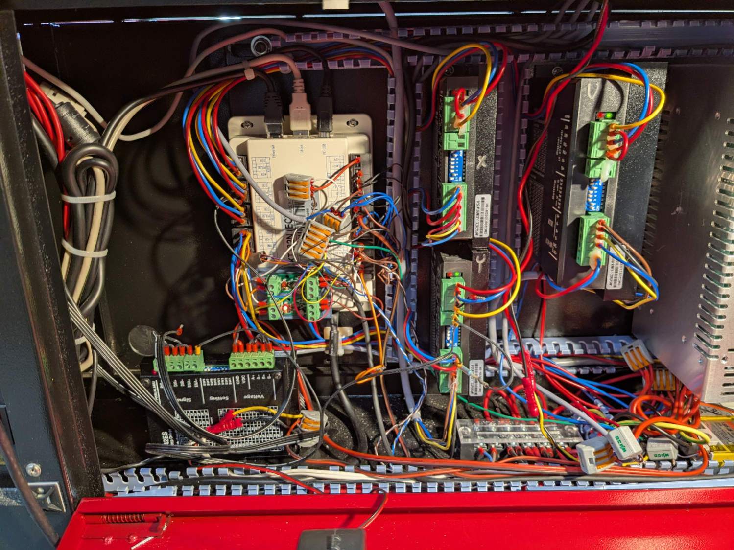
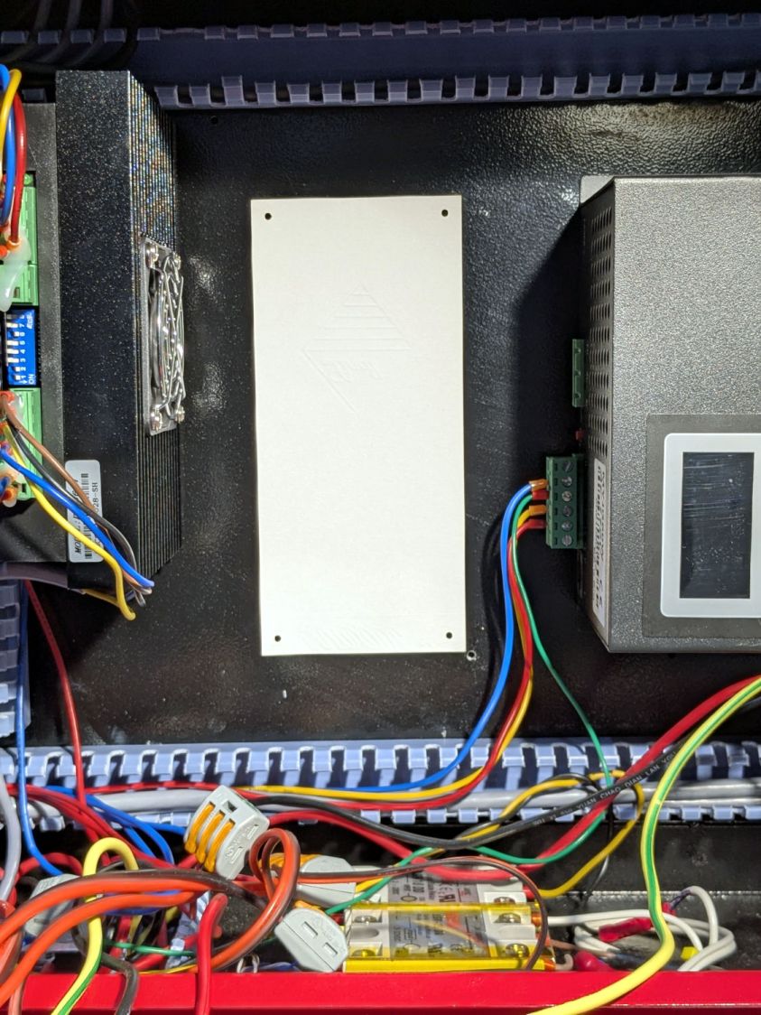
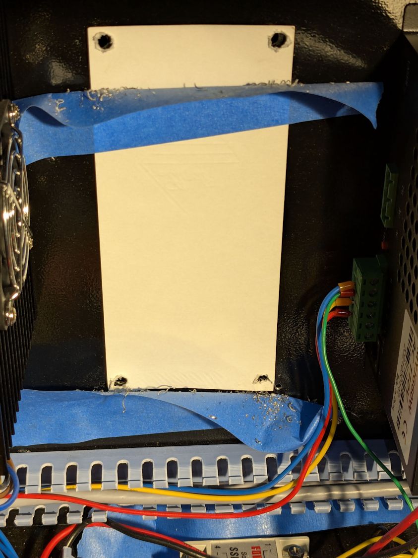
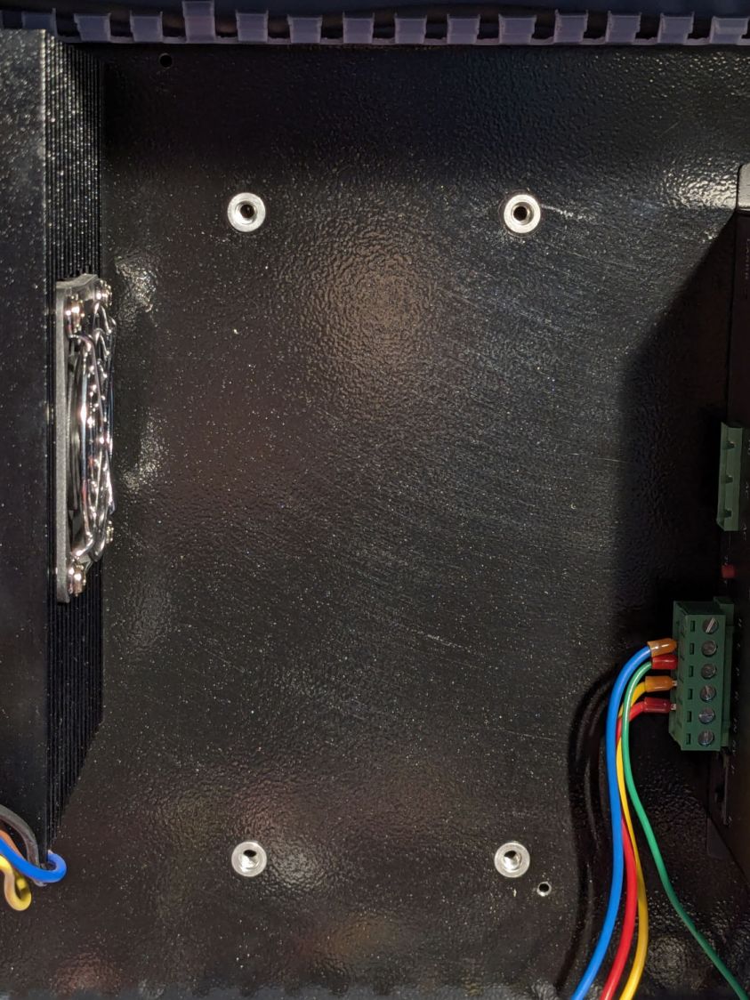
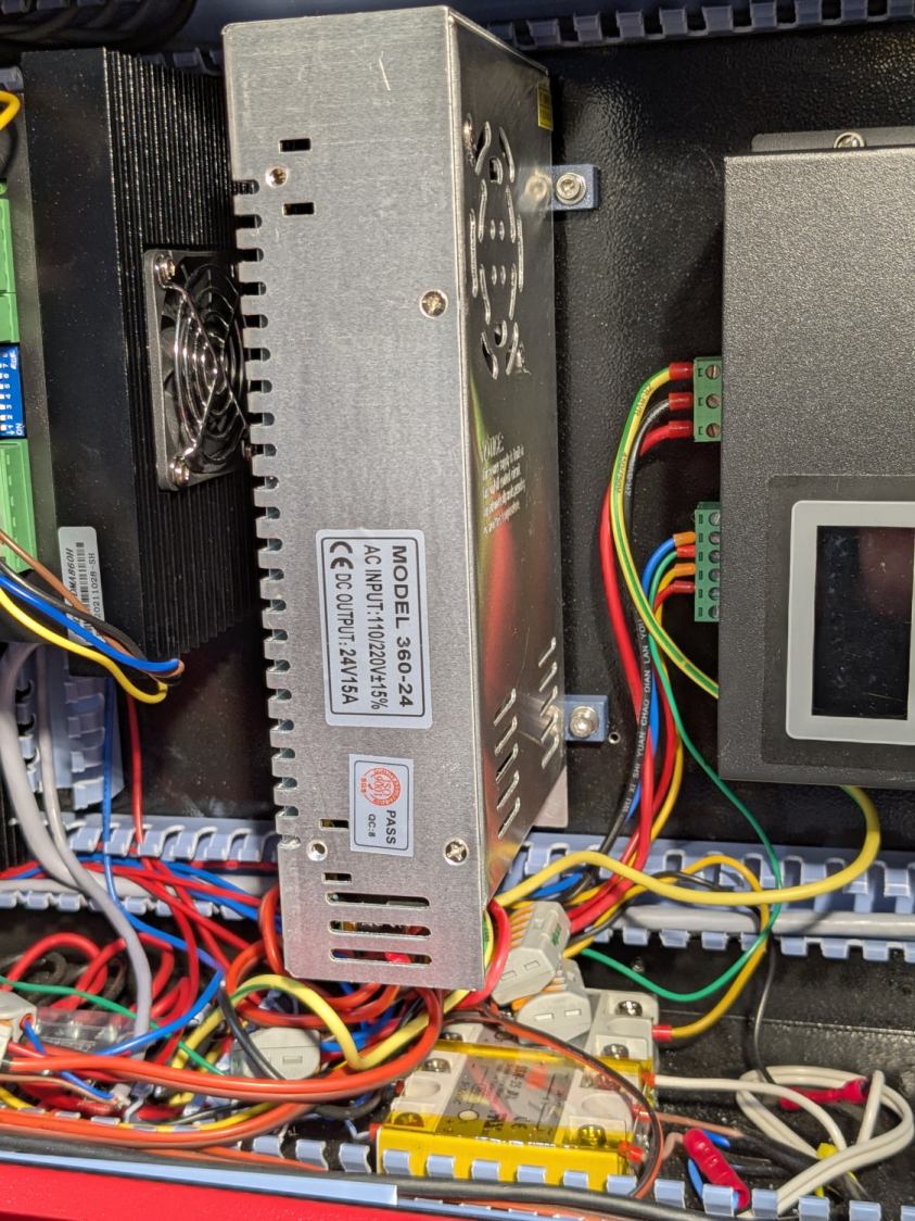
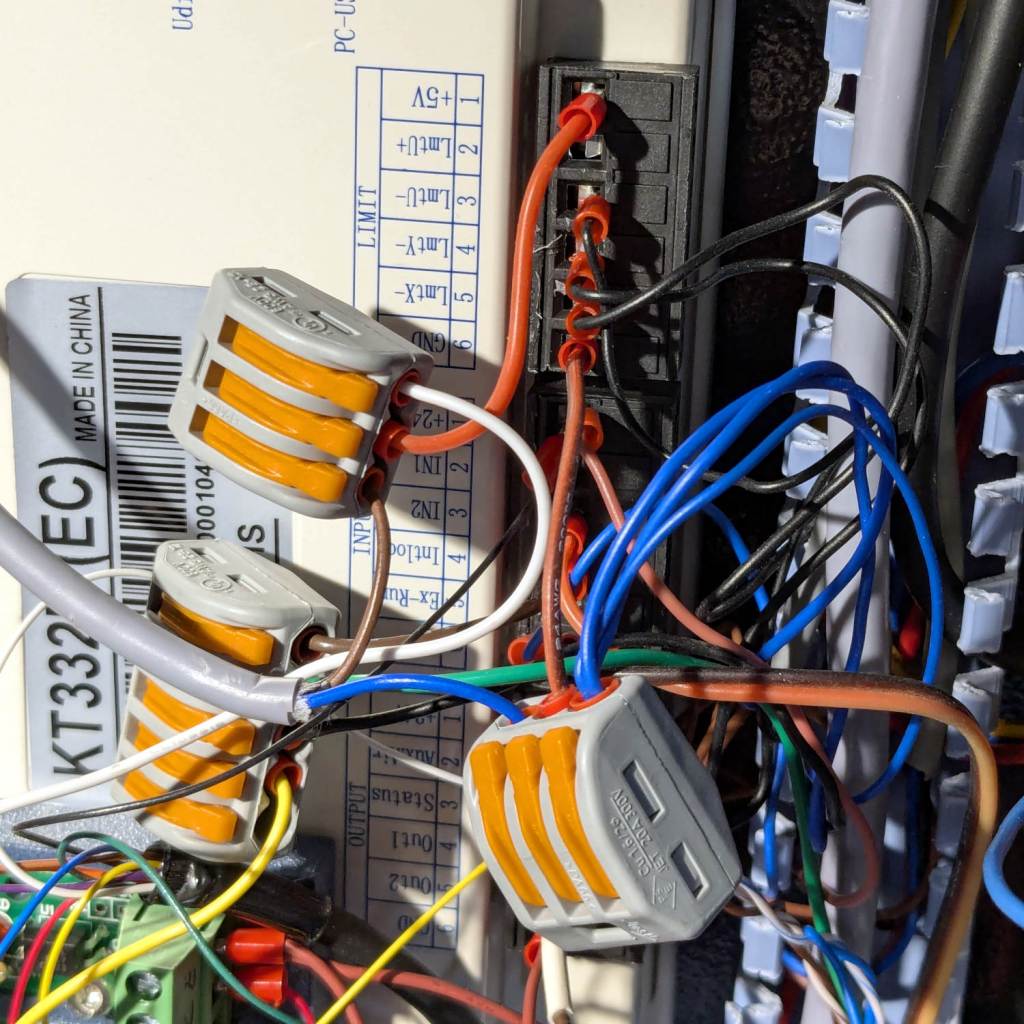
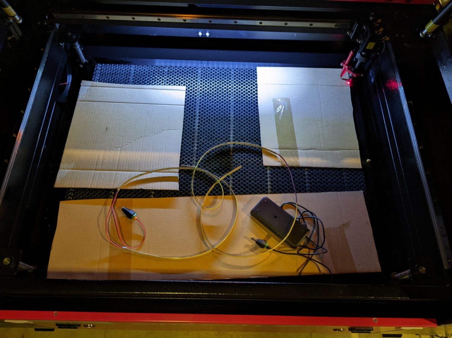
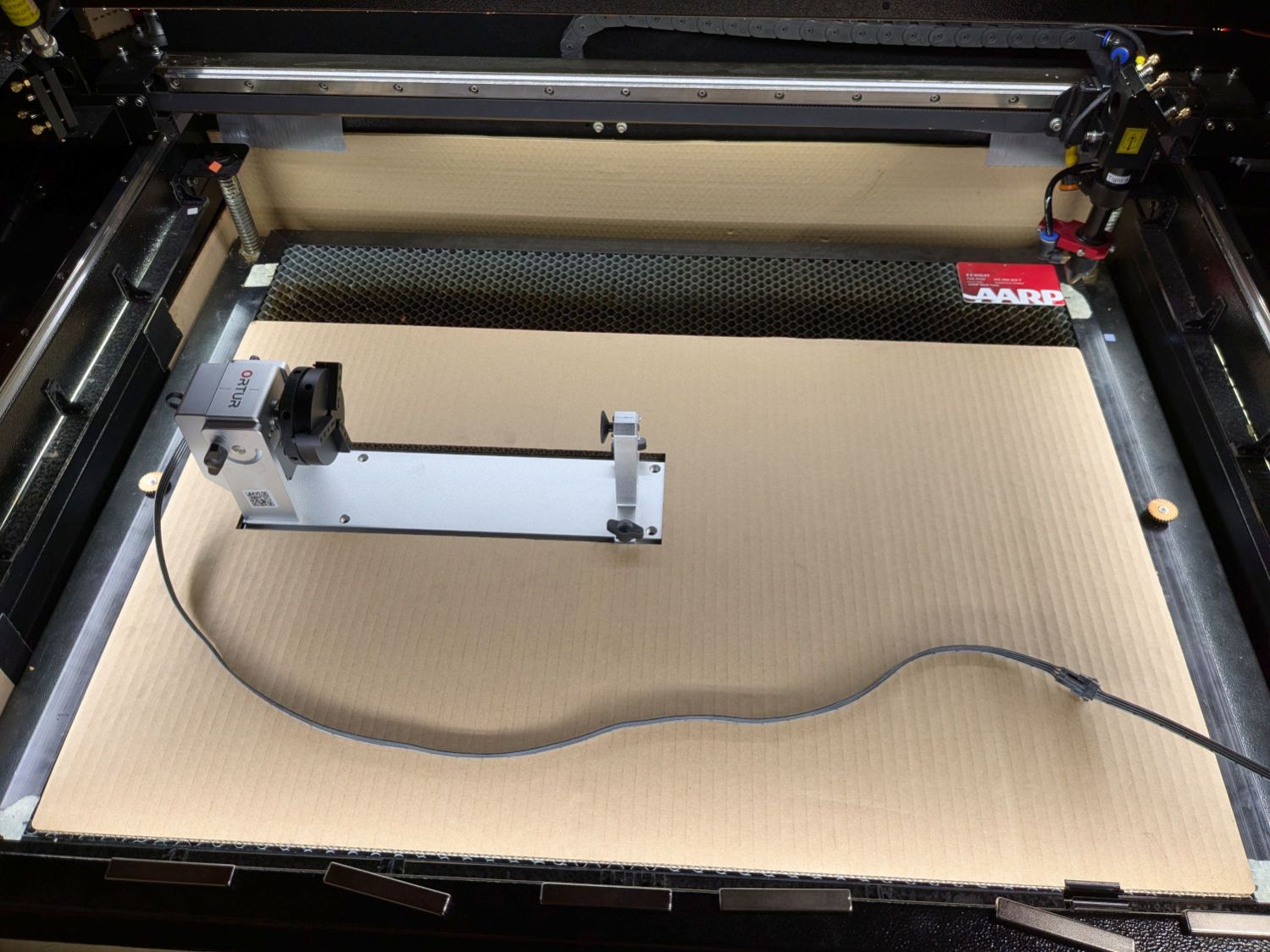
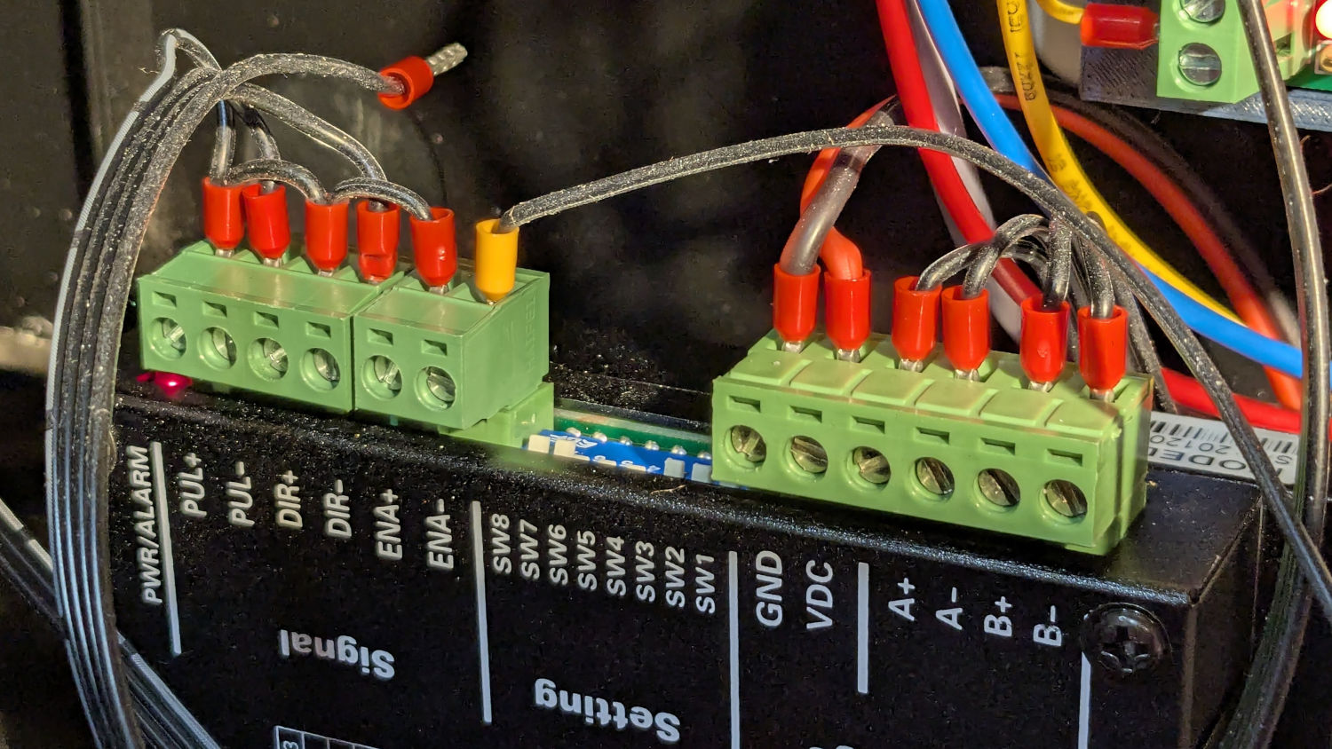
The ribbon cable burrows through the guts of the machine to the A/B terminals of the smaller stepper driver in the electronics bay:
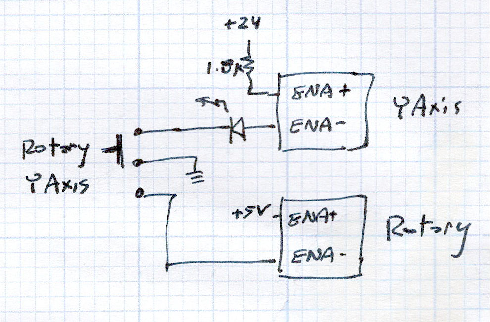
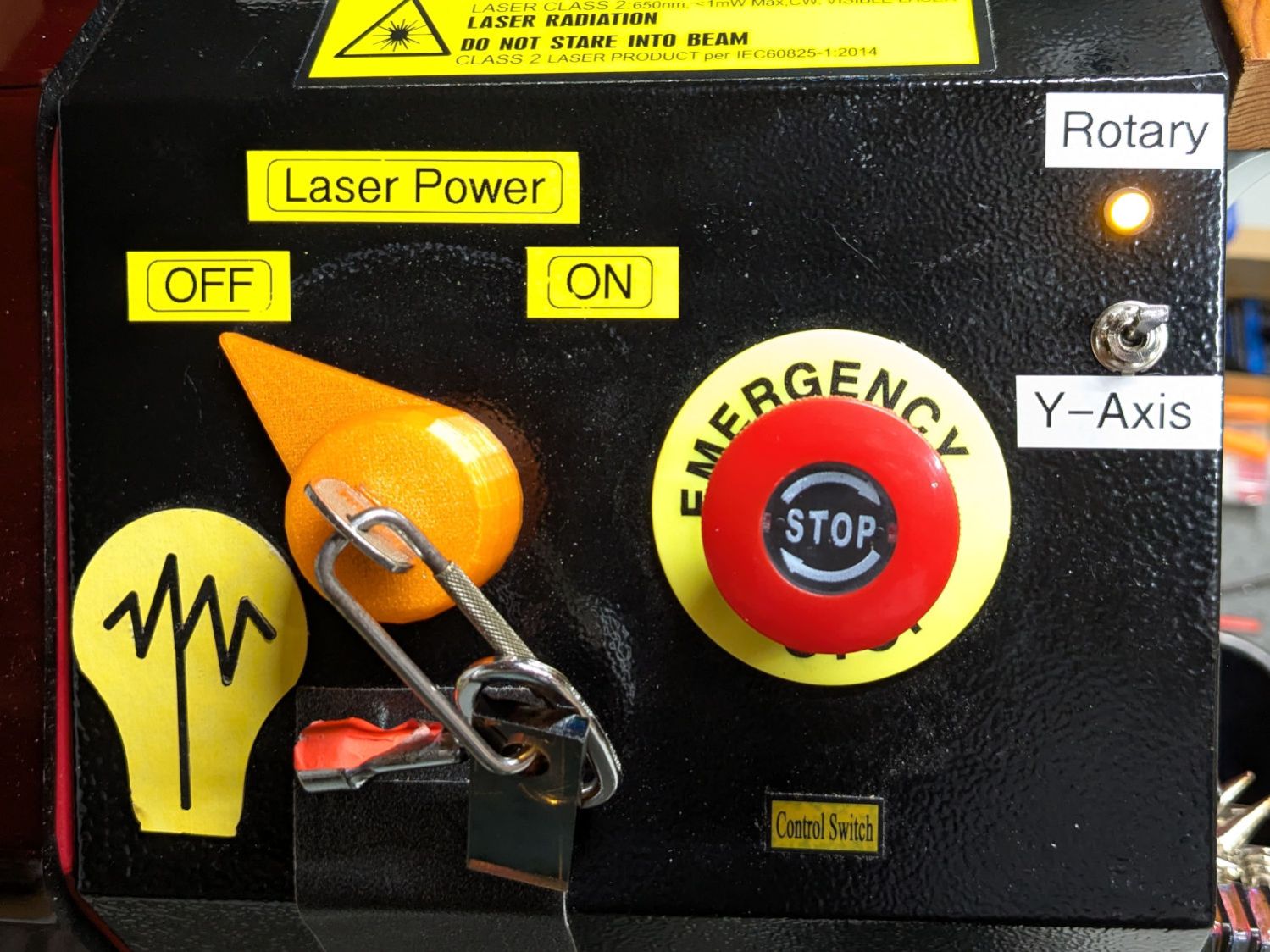
Flipping the front-panel switch to enable the rotary driver / disable the Y axis driver enthusiastically spins the chuck when the controller thinks I’m jogging the Y axis:
Making it do something useful requires more pondering.