Ed Nisley's Blog: Shop notes, electronics, firmware, machinery, 3D printing, laser cuttery, and curiosities. Contents: 100% human thinking, 0% AI slop.
Tag: Improvements
Making the world a better place, one piece at a time
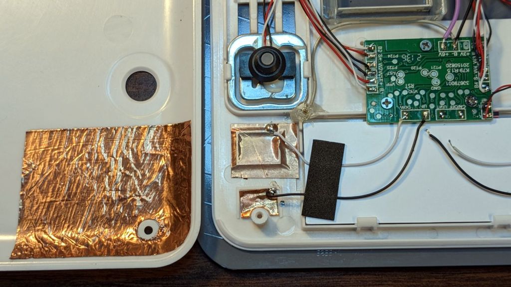
While I was thinking about something else, I added a back shield to our kitchen scale:
SmartHeart 19-106 Scale – button shield
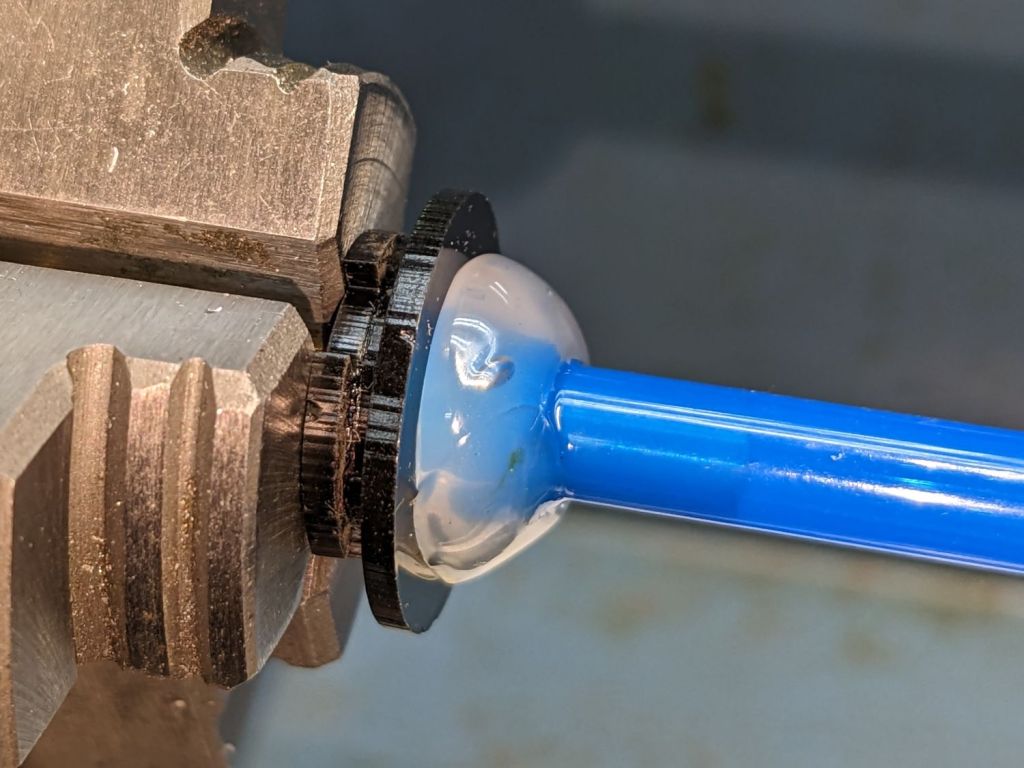
A pogo pin connected to the circuit common contacts the copper foil when the bottom cover is screwed down:
SmartHeart 19-106 Scale – shield pogo pin – detal
The shield prevents the buttons from responding to fingers on the bottom of the scale, so it no longer wakes up when I extract it from the under-cabinet shelf, and concentrates its attention on the buttons, so it no longer seems quite so willing to lock up due to mysterious influences.
With an absurd amount of rebuilding, this scale is becoming not a complete waste of free money.
The batteries soaked up 240 mA·hr of charge, which means the scale drew about 10 mA/day over the last three weeks. Given that the scale’s original 2032 lithium cells have a total capacity around 220 ma·hr for currents in the microamp range, expecting them to supply a current around 10 mA is was absurd.
Note that it’s possible to see the inlet, but not do much with it. I think the bottom plate could be pried off those squishy rubber pillars supporting / isolating the pump, but I didn’t see any need to do so.
The doodle I made at the time gives the dimensions:
OMTech 60 W Laser Air Assist – pump inlet fitting measurements
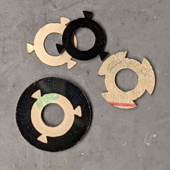
Back then, I thought of 3D printing the fitting, but the fact that the parts had to be 1.5 mm thick suggested laser cutting the parts from acrylic sheet:
Laser cutter air pump – keyed fitting A – parts
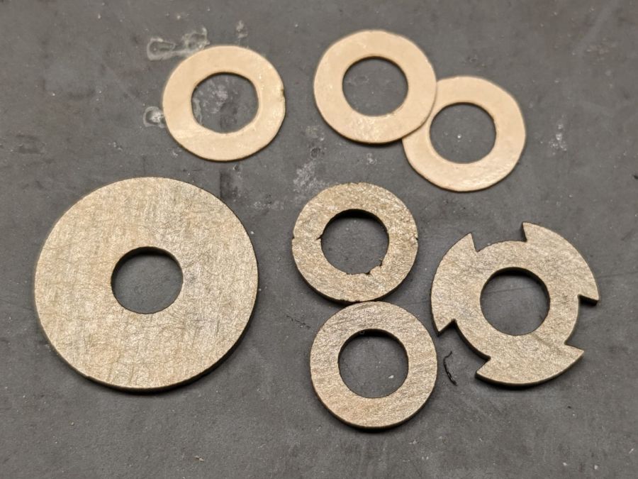
The three top disks come from a 3M LSE adhesive sheet and hold the three layers together, with one spare because I know better than to cut exactly as many as I think I’ll need:
Laser cutter air pump – keyed fitting – assembled
The alert reader will note the middle layer in that picture isn’t a simple round disk. After putting the first version together, I realized the keyed bottom layer could continue turning until it fell out, so I added stops to the middle disk:
Laser cutter air pump – keyed fitting B – parts
Those stops came from the bottom layer layout by welding together three copies of the key opening:
Laser Cutter Air Assist Pump Fitting – LB design layout
Space three of those shapes around the ring, subtract them from the outer disk (the same size as the keyed layer), weld them to the middle disk (the same size as the previous middle), and the stops appear as if by magic. Gotta love this geometry stuff.
The same design produced matching adhesive disks that I applied with tweezers, but if you were doing it in production you’d definitely want to apply a sheet of adhesive to a sheet of acrylic and cut them in the same operation.
Soften the slightly curved PVC tubing with a heat gun, persuade it to become straight, jam a drill bit inside and grab it in the lathe chuck to keep the fitting perpendicular, glob hot-melt glue around the tubing to hold it in place, and let it cool:
Laser cutter air pump – fitting hose glue
Hot melt glue doesn’t adhere well to acrylic, so cut & apply a disk of LSE adhesive between them, because it sticks like … glue … to both substances.
Mark and step-drill a hole in the bottom of the laser cabinet, install the fitting on the pump, line things up, and it’s ready to screw down:
Laser cutter air pump – first trial fitting
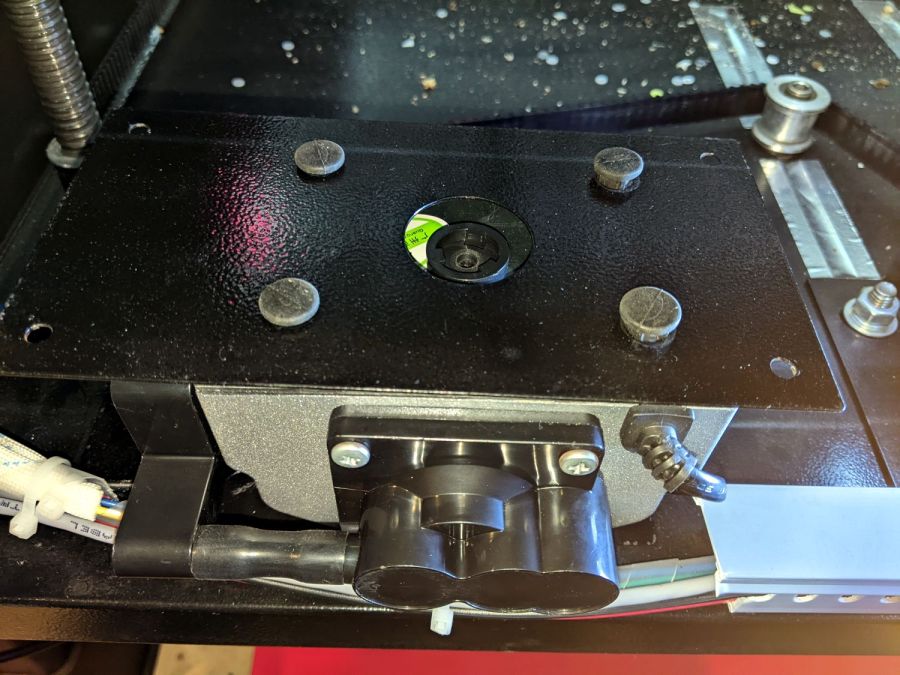
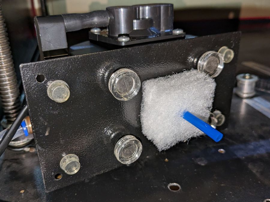
Whereupon I discovered the four silicone rubber feet I added to support the pump base plate and keep it from vibrating against the cabinet let the flexy rubber posts supporting the pump extend too far, thus causing the whole pump to rest on the glue around the fitting.
Well, I can fix that and, while I’m at it, a snippet of fibrous stuff will keep the tube from rattling around:
Laser cutter air pump – bottom view – assembled
The four clear disks are 3 mm acrylic stuck to the rubbery feet with more LSE adhesive, with rings around the top to keep everything aligned. It may be possible to line up all four of those things while lowering the pump in place, but not for me.
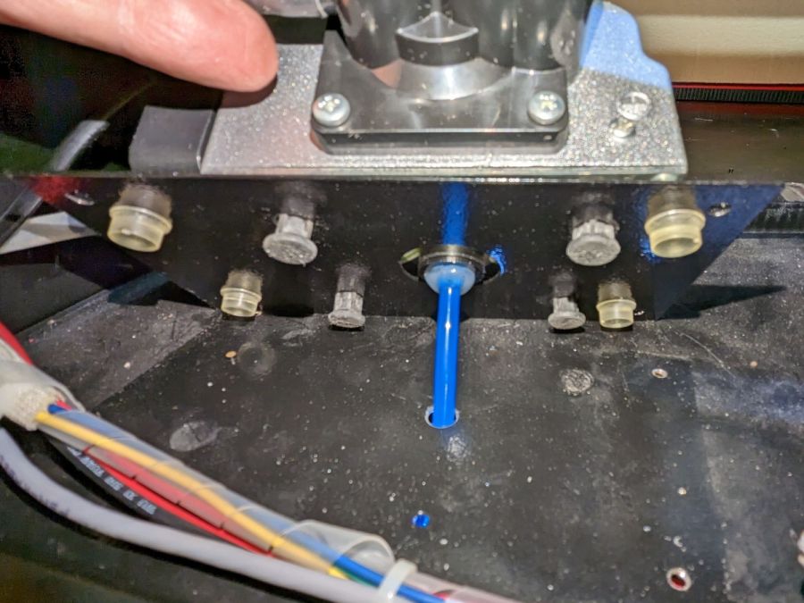
With all that once again ready to screw down, the blue tube and its fuzzy felt bumper fell right off, taking the pump’s air inlet connector along. Much to my surprise, the pump draws air through a simple 6 mm hole in its bottom plate:
Laser cutter air pump – without fitting socket
Now, the reason I went through all these gyrations was because I had examined that connector, decided it was an integral part of the pump, and there was no way for me to get it off without tearing the pump apart or applying brute force.
Apparently, all the twisting & turning I did while getting the fittings assembled worked the connector’s unthreaded stem loose in its hole, ready to come out with the slightest pull.
Verily: Hell hath no fury like that of an unjustified assumption.
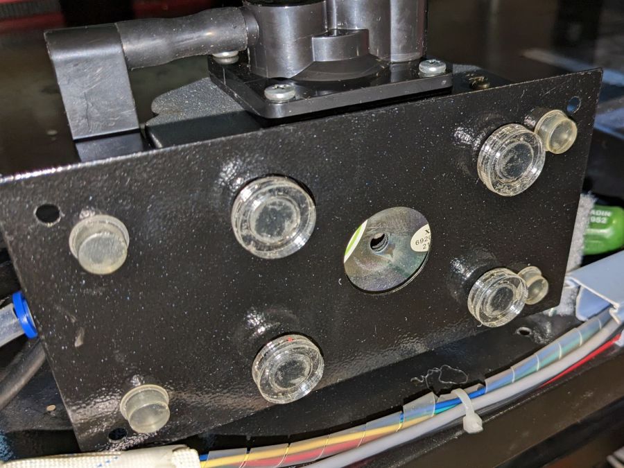
So I cut out a simple disk of 4.5 mm acrylic, hot-melt blobbed a 6 mm ID silicone tube into it, stuck it onto the pump with a (punch-cut!) disk of 3M double-sided foam tape, and declared victory:
Laser cutter air pump – simple disk fitting
Fortunately, the step drill I used on the cabinet left a 9.5 mm hole easily passing the silicone tube’s 9 mm OD, so it all fit together just like I knew what I was doing.
The silicone tubing has a much larger ID than the original plastic fitting, but the assist air flow remains around 10 l/min. That’s down from the 14 l/m when I installed the flowmeter and 12 l/min with the dual-path assist air control plumbing, but didn’t change with all this fiddling, so the real restriction is in all the blue tubing and myriad fittings on the way to the nozzle.
On the upside, I now know a bit more about small-scale laser cutting and am well-satisfied with the results.
The C100+ has a non-replaceable lithium pouch battery that may not last for the hour or so we generally ride, but at least this is a starting point for seeing how the thing works.
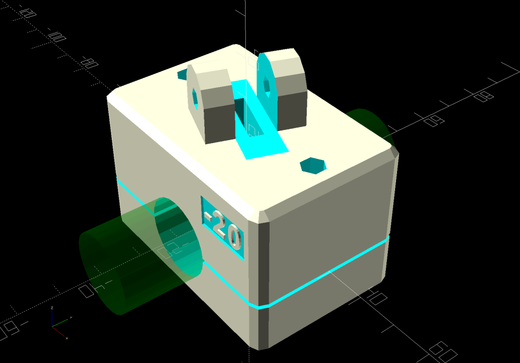
The PrusaSlicer preview shows the support structure inside the seat rail arches:
SJCAM C100 Mount – slicer
That appears under the four central facets of each arch, where I “painted” the support enforcers, because the automagic supports fill the entire arch and are basically impossible to pry off.
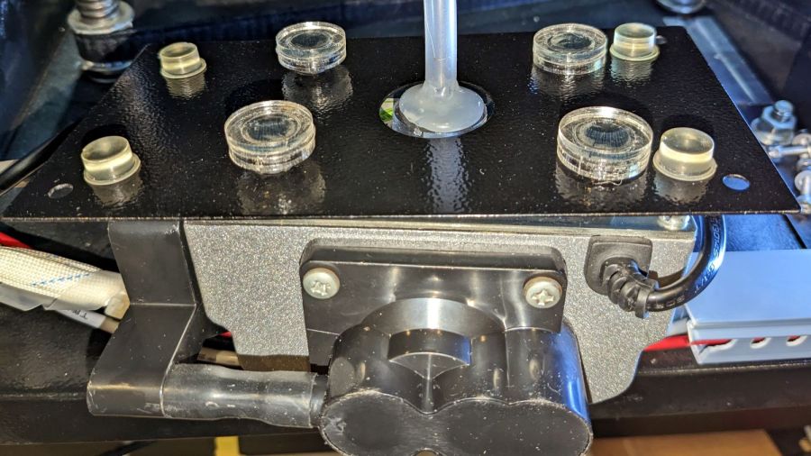
The hole between the ears on the top holds an aluminum tab intended to diffuse the wobble from that tall camera. A laser-cut chipboard template simplified drilling & cutting the tab from an aluminum sheet:
Tour Easy – SJCAM C100 mount – test fit
The tab and the brass inserts are held in place with JB Weld Plastic Bonder, my new go-to adhesive for such things.
The camera includes WiFi and the inevitable app lets you download images without opening the case. Because I’ll be charging the camera after each ride, I may as well just haul the whole thing inside, plug it into a USB port, and proceed as before.
For future reference, the manual details the operating modes:
SJCAM C100 Manual – Modes
Because the camera powers up with WiFi enabled and I have no plans to communicate with it while riding, the startup sequence will be:
This file contains hidden or bidirectional Unicode text that may be interpreted or compiled differently than what appears below. To review, open the file in an editor that reveals hidden Unicode characters.
Learn more about bidirectional Unicode characters
The stock Bafang pedal cranks measure 170 mm on centers between the bottom bracket shaft and the pedal spindle. Having grown accustomed to the 165 mm cranks from Mary’s bike, I got a set of cheap 160 mm cranks to feel if there was any difference:
Bafang vs ProWheel crank forging
The bottom crank has a quick-and-dirty adaptation of the magnet mount for the Lekkie Buzz Bar offset cranks, but, of course, the 160 mm cranks have an entirely different profile. They are also heavier and more crudely forged, which is about what you’d (well, I’d) expect.
Also unlike the Lekkie cranks, neither the Bafang nor the Prowheel cranks correct the Bafang motor’s offset, so I’m using the left-side Kneesaver from the old cranks, which turns out to be close enough.
The black 3D printed mount in the upper right fit the Bafang crank and appears in the top photo.
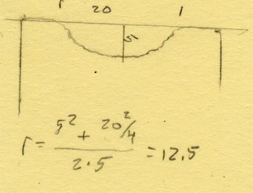
Transferring the new contour to paper and applying the Chord Equation got the radius of the not-quite circle:
CatEye magnet crank adapter – chord radius
Knowing the size of the magnet and the radius of the circle, drawing the profile in LightBurn was straightforward:
CatEye magnet crank adapter – framed
Applying the laser cutter to MDF produced the two successive test-fit pieces in the picture while figuring out how much stickout the magnet needed beyond the inner crank face to reach the sensor. LightBurn’s Node Editor simplified adjusting the size: drag-select a group of nodes, then move them in precise increments with the arrow keys.
Export the profile from LightBurn as an SVG file, import it into OpenSCAD, and extrude it to the proper length:
The translate puts the profile approximately at the XY origin. The center = true option moves the profile elsewhere on the XY plane, but does not center it, which may have something to do with the viewport used by LightBurn, the OpenSCAD version I’m using, or something else entirely.
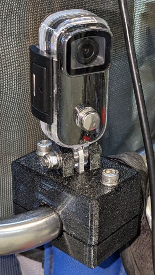
In any event, the 3D printed mount fits the crank and puts the magnet where it will do the most good:
CatEye Magnet holder – ProWheel crank – installed
What looks like an obvious curvature mismatch comes from having the tape edge not quite squashed against the crank.
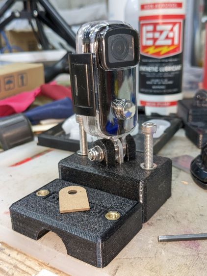
I should poke a channel through it for a cable tie around the crank, but that 3M foam tape is really good stuff and hasn’t failed me yet.
It’s basically ten identical identical spacers cut from 3 mm plywood, with a side benefit of dramatically reducing my scrap plywood stash, then skewered by a pair of absurdly long 4 mm self-tapping metal screws into holes drilled half an inch into the ¾ inch solid wood cabinet floor.
It clears some clutter atop the microwave and, at least to my deflicted ears, sounds much better. At some point I must screw the Raspberry Pi under the cabinet, too, but that awaits further rearrangement.
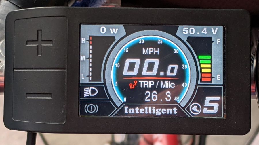
I got the Bafang DPC-18 display for my Tour Easy specifically to put the control buttons on the handgrip, rather than the buttons on the left of the 500C display on Mary’s bike:
Tour Easy Bafang – display 26 mi
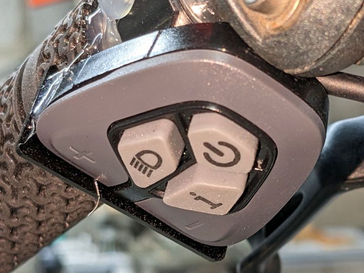
The first pass put them on the left handgrip, just behind the thumb throttle:
Bafang DPC-18 control buttons – initial mount
This turned out to be a catastrophically bad position, because the “buttons” extend all the way to the edge of the mount and trigger when pressed a fraction of a millimeter: the dark line visible under the light gray top is the entire range of motion.
My resting hand position on the grip put the edge of my gloved index finger along the buttons, where it would inexorably nudge the + button until I was riding in assist level 9 (Rocket Sled) mode.
One ride was enough to convince me those buttons needed a Mollyguard:
It is, of course, a laser-cut piece of 1.5 mil black acrylic, held in place with hot-melt glue. Because the button housing isn’t mounted symmetrically on the handlebar, I cut a few paper templates before getting the position and size right.
A view from the front shows the lip sticking up over the buttons:
Bafang DPC-18 button Mollyguard – front view
FWIW, the asymmetric mount put the buttons on the rider’s side of the flat handlebars found on contemporary upright city-rider style bikes. It makes perfect sense in that context, but didn’t help me in the least.
With the Mollyguard in place, I rotated the whole button assembly around the handgrip to allow pushing the buttons with my thumb in its natural position.
Now the assist level changes only when I want it to!