Ed Nisley's Blog: Shop notes, electronics, firmware, machinery, 3D printing, laser cuttery, and curiosities. Contents: 100% human thinking, 0% AI slop.
Tag: Improvements
Making the world a better place, one piece at a time
Some geometry review and a bit of fiddling with LightBurn produced regularized patterns suitable for laser cuttery:
Danger Zone Earrings – radioactive – handful
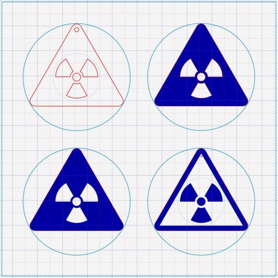
A key trick: circumscribe the figure with a circle on a tool layer, then group the whole mess together, so that the center of the circle coincides with the desired center of the figure. In particular, the geometric center of an equilateral triangle is not at the center of its vertical extent:
Danger Zone Earrings – radioactive – LB layout
The dark blue layer engraves the surface, the red layer cuts through 3 mm acrylic, and the light blue layer is the tooling.
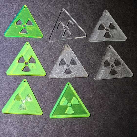
I like the edge-lit ones, although the simplicity of laser-cut clear acrylic is hard to beat:
Danger Zone Earrings – radioactive – white light
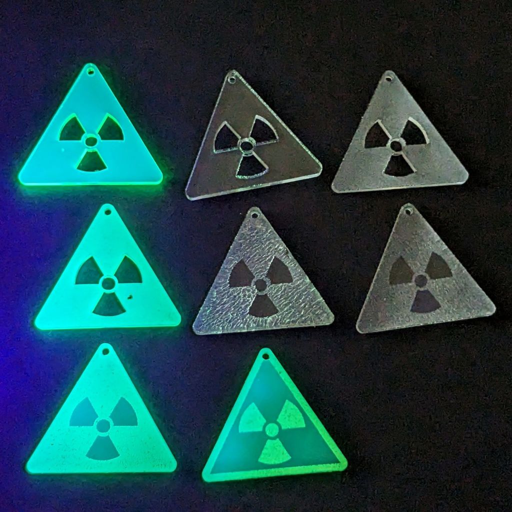
Wearing them in a place flooded with UV radiation would set you apart:
Danger Zone Earrings – radioactive – GITD UV
The careful observer will note stress cracking in the two clear earrings in the middle row. Those came from the vintage paper-covered acrylic sheet and I used alcohol to clean off the not-quite-vaporized glue just to see if isopropyl alcohol would behave differently than denatured alcohol. Nope, the cracks appear instantly.
Peeling the paper and engraving the bare surface produced the clear-frosted earring in the upper right, with the radiation symbol cut out of the sheet. Engraving without surface protection tends to deposit vaporized acrylic dust everywhere, so it would require hand cleaning without the cutouts.
The cutouts get 0.1 mm inward offsets to slightly increase the wall thickness around that central circle.
One combination I didn’t try: engrave the triangle perimeter for emphasis and cut out the symbol for contrast with edge-lit acrylic.
Dropping other symbols into place should be straightforward, with the center of the circumcircle as the snap target.
Using Bash arrays is an exercise in masochism, but I got to recycle most of the oddities from the previous script, so it wasn’t a dead loss.
The cameras use individually unique / screwy / different filesystem layouts, so the script must have individual code to both copy the file and decapitalize the file extensions. This prevents using a single tidy function, although laying out the code in case statements keyed by the camera name helps identify what’s going on.
My previous approach identified the MicroSD cards by their UUIDs, which worked perfectly right up until the camera reformats the card while recovering from a filesystem crash and installs a randomly generated UUID. Because there’s no practical way to modify an existing UUID on a VFAT drive, I’m switching to the volume label as needed:
In particular, note the two UUIDs for the M20 camera: there’s a crash and reformat in between those two lines. The two C100 cameras started out with labels because the M20 taught me the error of my ways.
The script simply iterates through a list array of the cameras and tries to mount the corresponding MicroSD card for each one: the mount points are cleverly chosen to match the camera names in the array. Should the mount succeeds, an asynchronous rsync then slurps the files onto the bulk video drive.
With all the rsync operations running, the script waits for all of them to complete before continuing. I don’t see much point in trying to identify which rsync just finished and fix up its files while the others continue to run, so the script simply stalls in a loop until everything is finished.
All in all, the script scratches my itch and, if naught else, can serve as a Bad Example™ of how to get the job done.
A picture to keep WordPress from reminding me that readers respond positively to illustrated posts:
This file contains hidden or bidirectional Unicode text that may be interpreted or compiled differently than what appears below. To review, open the file in an editor that reveals hidden Unicode characters.
Learn more about bidirectional Unicode characters
As expected, the internal battery does not last for our usual hour-long rides, so the cameras now operate in “car mode”: recording starts when we plug in the USB battery pack and stops shortly after unplugging.
I started with the waterproof case on my bike:
Tour Easy – SJCAM C100 mount – installed
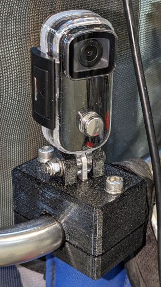
Which (obviously) does not allow for an external battery, so they’re now in the “frame” mount. The hatch covering the MicroSD card and USB Micro-B connector (and a Reset button!) is on the bottom of the camera, but (fortunately) the whole affair mounts up-side-down and the settings include an image flip mode.
The ergonomics / user interface of this whole setup is terrible:
The camera’s flexible hatch is recessed inside the frame far enough that it cannot be opened without using a small & sharp screwdriver
The USB jack is slightly off-center, so lining the plug up with the camera body doesn’t align it with the jack
The MicroSD card is in a push-to-release socket, but its raised ridge faces the hatch flap and cannot be reached by a fingernail. I added a small tab that helps, but it’s difficult to grasp.
Extracting the video files from the camera through the app is an exercise in frustration. Having already figured out how to do this for the other cameras in the fleet, it’s easier to fumble with the MicroSD card.
I devoutly hope we never really need any of the videos.
The trail camera uses two parallel banks of four series AA cells to get enough oomph for its IR floodlight. I’m not convinced using bucked lithium AA cells in that configuration is a Good Idea, but it’s worth investigating.
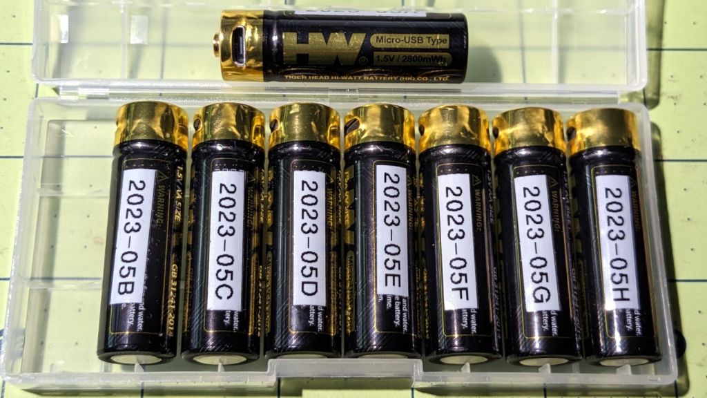
These are labeled HW, rather than Fuvaly, because it seems one cannot swim twice in the same river:
HW bucked Li AA cells
In any event, they come close to their claimed 2.8 W·hr capacity:
HW bucked Li AA – 2023-05
The lower pair of traces (red & black) are single cells at 2.7-ish W·hr, the blue trace is a pair at 5.4 W·hr, and the green trace is a quartet at 9.8 W·hr. Surprisingly close, given some previous results in this field.
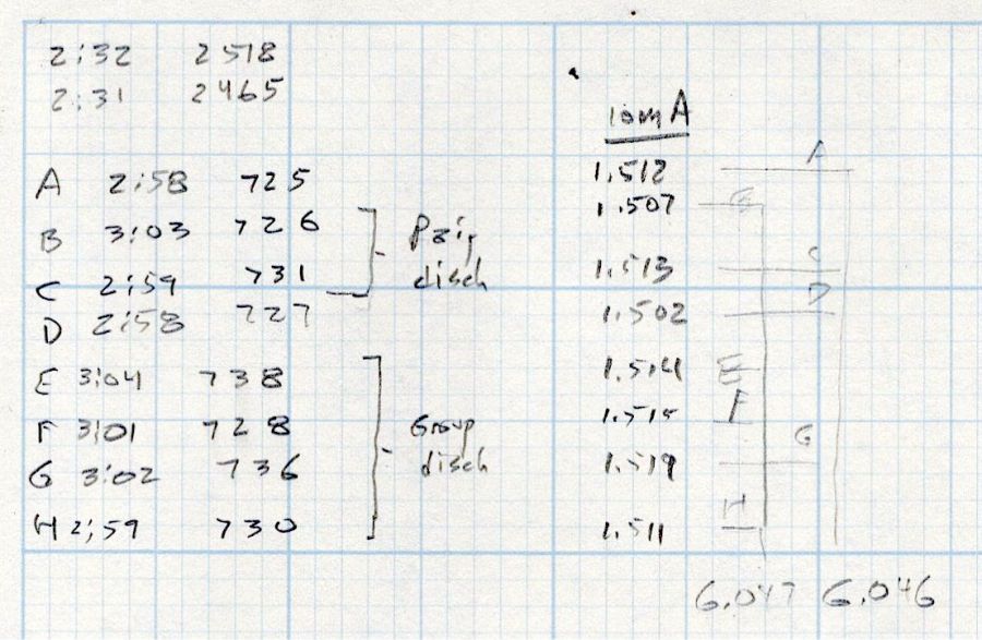
Recharging the cells after those tests shows they all take 3 hours ± a few minutes to soak up 730 mA·hr ± a few mA·hr, so they’re decently matched.
Measuring the terminal voltage with a 10 mA load after that charge lets me match a pair of quartets to 1 mV, which is obviously absurd:
HW bucked Li cells – initial charge 2023-05-05
The numbers in the upper left corner show the initial charge of four cells at a time required the same time within a minute and the same energy within 4%.
Sticking them in the trail camera must await using up the current set of alkaline AA cells.
Bonus: a lithium fire in a trail camera won’t burn down the house.
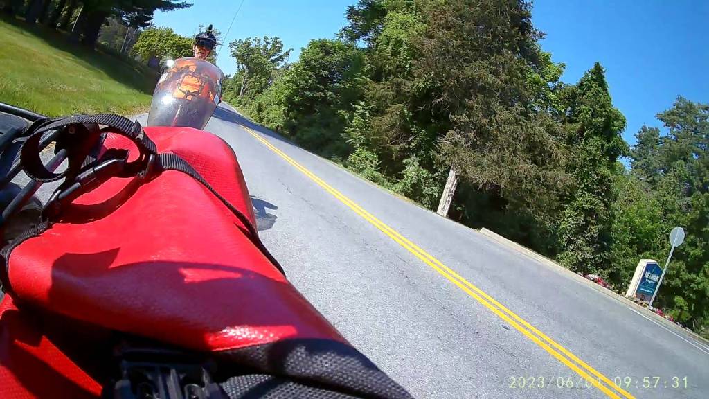
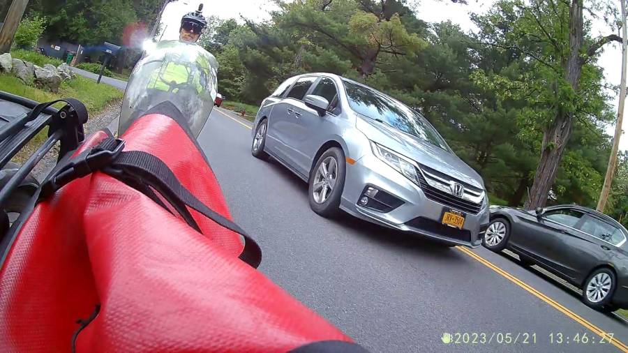
After all, pictures like this are definitely worth the hassle:
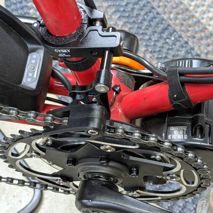
It’s more properly called a “chain guide” and is basically a shifter cage minus the mechanism:
Chain Catcher – side view
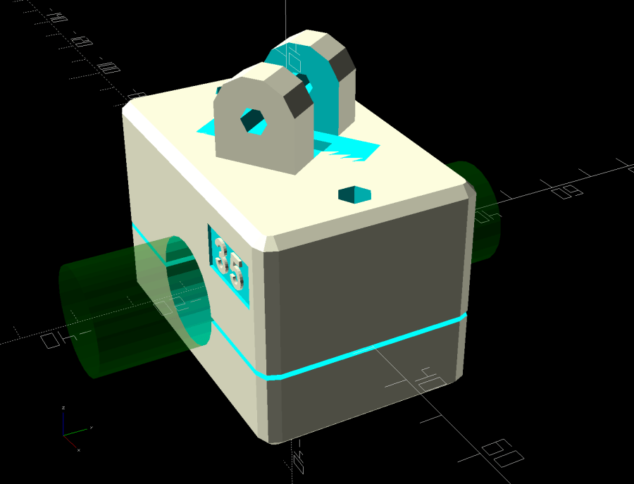
Because the Tour Easy frame has a 25 mm tube where the guide’s clamp expects a minimum 31.8 mm tube, a 3D printed adapter fills the gap:
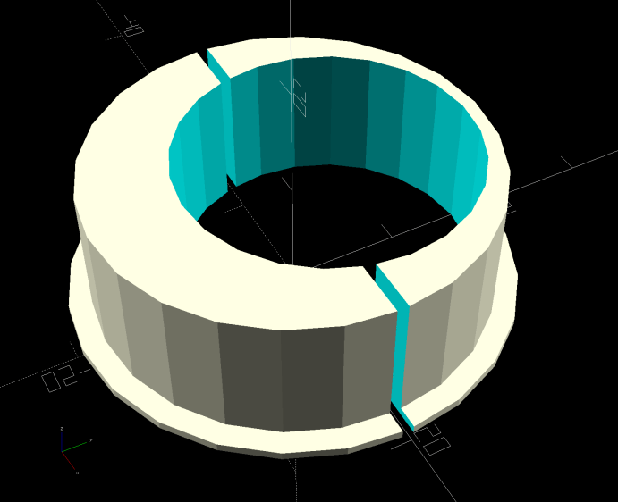
Chain Catcher adapter ring – solid model
The hole is off-center because it seemed like a good idea, although it’s not strictly necessary. The flange helps align the pieces while tightening the clamp screw.
The guide cage clears the chain on all sides while up on the work stand, but there’s nothing like getting out on the road to find out why something doesn’t work as you expect.
This file contains hidden or bidirectional Unicode text that may be interpreted or compiled differently than what appears below. To review, open the file in an editor that reveals hidden Unicode characters.
Learn more about bidirectional Unicode characters
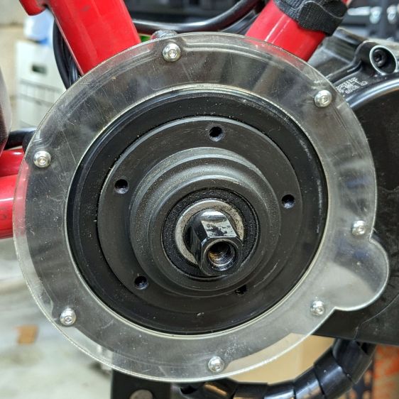
When the chain falls off the top of the chainring toward the motor, the part remaining engaged with the chainring will inevitably drag the rest into the gap between the motor and the chainring spider, whereupon it will jam firmly in place and be almost impossible to extract. Preventing this means filling the gap, which required several iterations:
Bafang motor gap filler – prototypes
The Bafang motor has a cover held in place by seven M3 flat-head screws, shown here below a test filler using pan head screws:
Bafang motor gap filler – installed
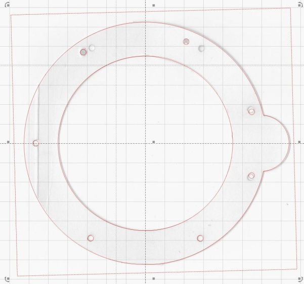
Contrary to what you might think, the five screws that obviously sit on five points of a hexagon do not in fact sit 60° apart. How you find this out is by making the obvious layout, including the two screws bracketing the pinion gear in the lower right, then applying windage:
Bafang motor housing gap filler – hole adjustments
That’s one of the paper templates seen above, with laser-cut holes 60° apart and ugly holes punched at the actual screw locations. Then you scan and overlay that image with the LightBurn layout and twiddle the hole locations to make the answer come out right:
Bafang motor housing gap filler – hole adjustments – LB overlay
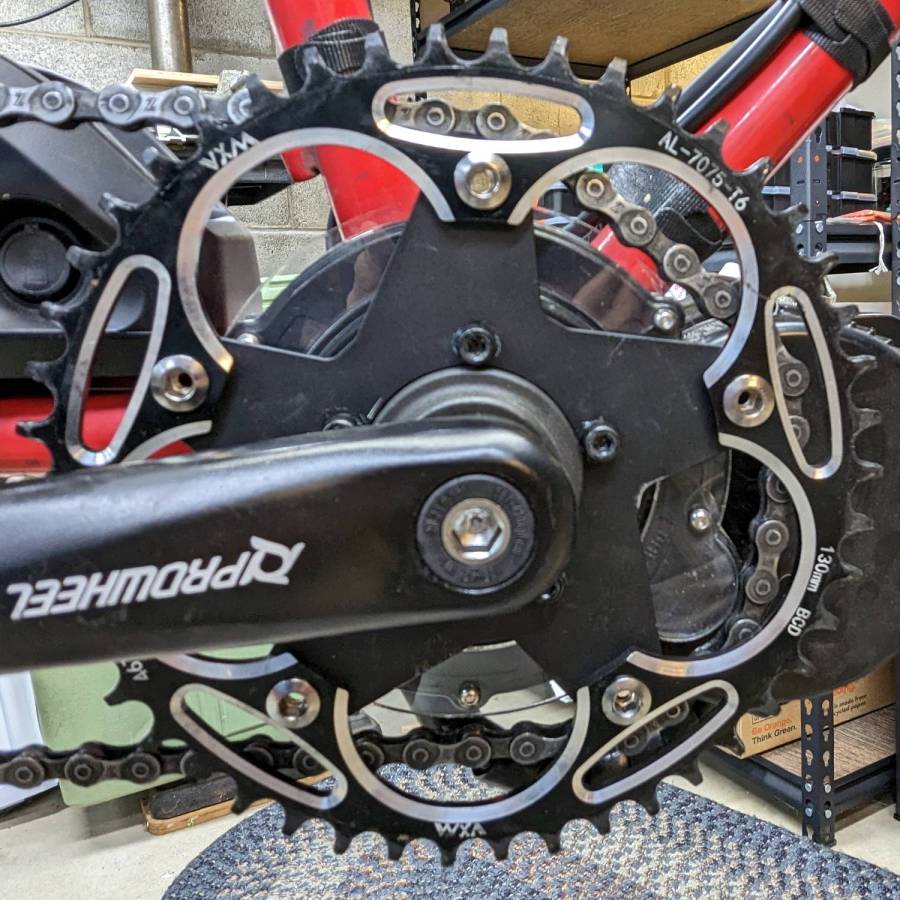
With that in hand, I cut a 1 mm acrylic shape to measure the clearance between the motor + filler and the chainring spider, with pan-head screws replacing the original flat-head screws:
Bafang motor gap filler – top view
That’s a single piece of 2.5 mm acrylic I used after discovering a pair of the 1 mm acrylic shapes fit with space to spare: hooray for rapid prototyping.
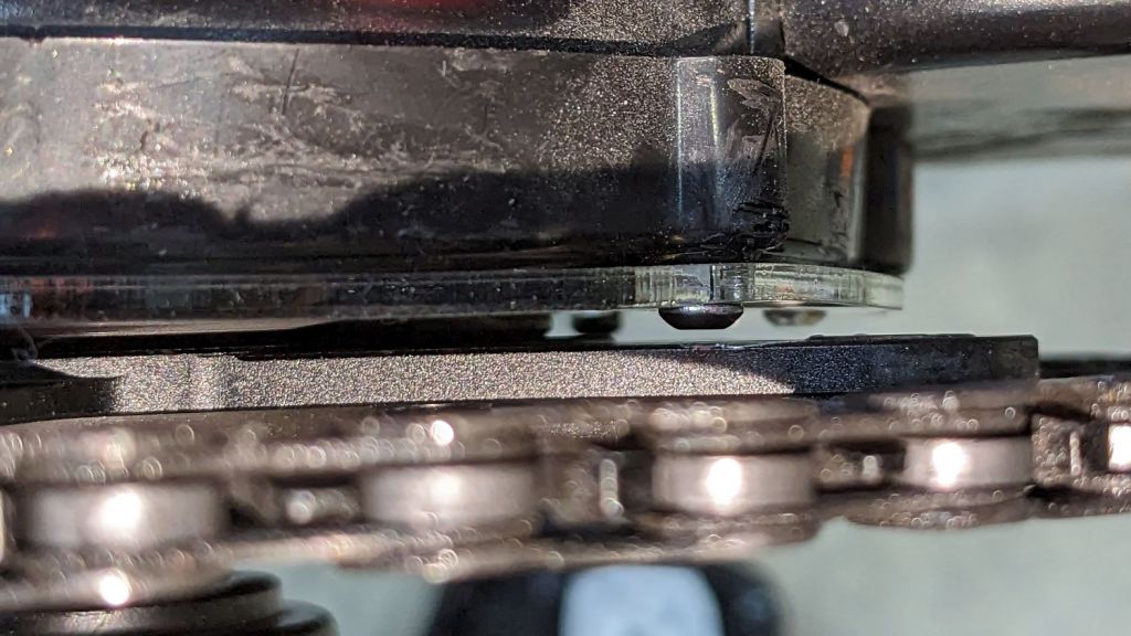
A test chain drop suggested it might suffice:
Bafang motor gap filler – test
If I were so inclined, 3 mm acrylic with countersunk holes and slightly longer flat-head screws would probably work, but I’ll use this until it fails to prevent a chain snag.
The careful observer will have noted the stress crack extending radially inward from the upper-right screw, which I am carefully avoiding doing anything about, pending the aforementioned failure.
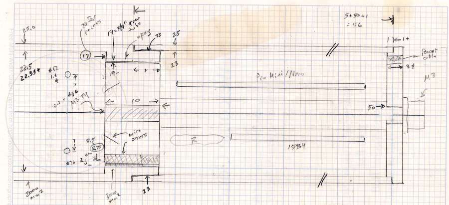
Having acquired some thick-wall (1 inch OD, ¾ inch ID) aluminum tube, making the LED heatsink and lens holder for a running light generates a lotless scrap. A new doodle gives the dimensions in a rather Picasso-ish layout:
Running Light – dimension doodles
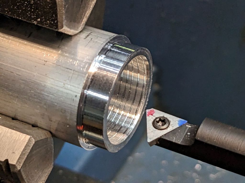
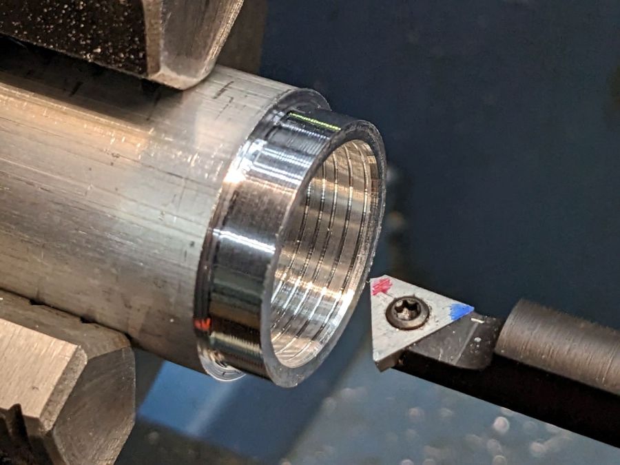
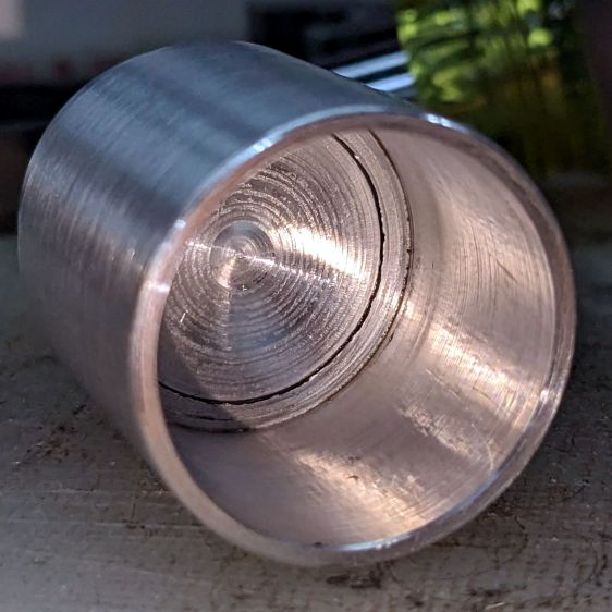
The back end of the tube gets turned down to 23 mm OD and cleaned up to 19 mm ID, then scored to give the epoxy something to grip:
Front Running Light – Heatsink shell scoring
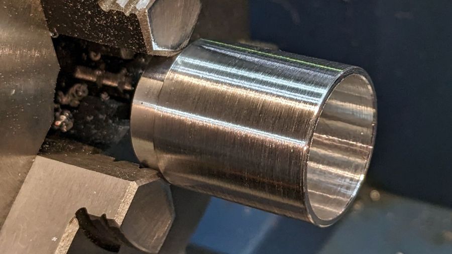
The front end gets bored to 22.5 mm for the lens holder and has its OD cleaned up to 25 mm:
Front Running Light – finished shell
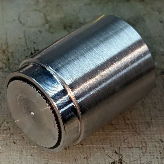
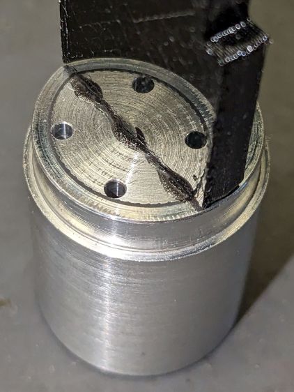
Clean up the end of a ¾ inch rod to 19 mm OD, knurl it a little to increase the OD ever so slightly and improve its griptivity, slice off a bit more than 10 mm, butter it up with JB Weld epoxy, and shove it into the shell with its front end aligned and its back end sticking out:
Front Running Light – epoxied plug in shell – rear
Face off the back end and the front end looks fine as assembled:
Front Running Light – epoxied plug in shell – front
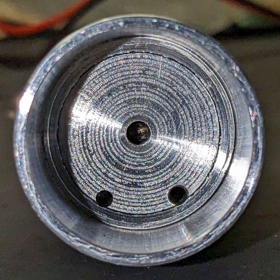
Grab it in the Sherline mill’s three jaw chuck to:
Drill & tap the M3 central hole for the stud holding the circuit plate to the back end
Drill 1.6 mm blind holes for the circuit plate pins
Drill 2 mm through holes for the LED wires, 60° apart
Which looks like this from the front:
Front Running Light – drilled heatsink – front
And like this with the circuit plate screwed & glued to the rear:
Front Running Light – circuit plate mounted
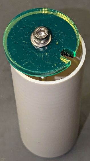
Clean up the OD of some ¾ inch PVC pipe to 25 mm, bore it out to 23 mm.
While the Sherline is set up, drill a pair of 2 mm holes in the lens holder for the wires, aligned so they’ll match the heatsink holes.
Because we live in the future, laser-cut the rear cap from some edge-lit acrylic with a black inner disk:
Front Running Light – PVC tube – end cap
Cutting that cap with the notch included is now trivially easy, compared to the previous machining.


