
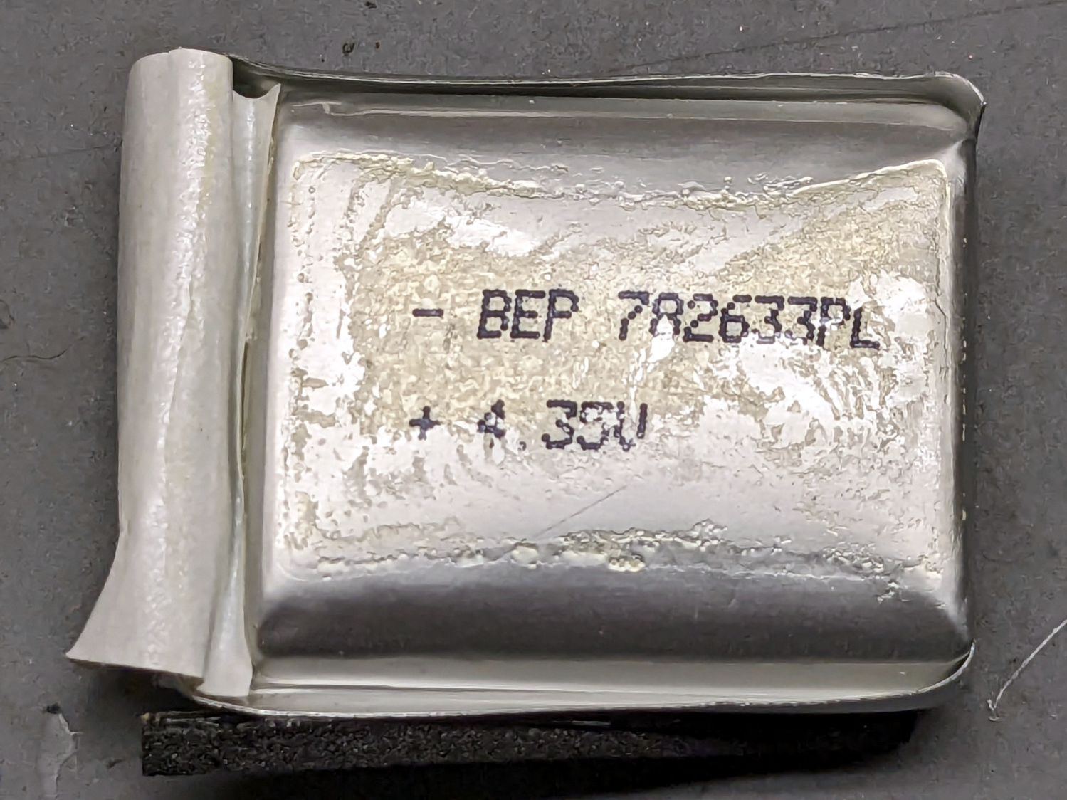
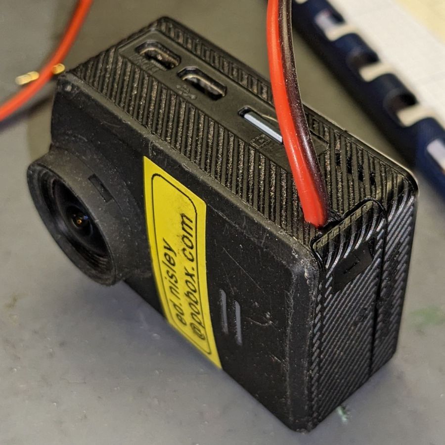
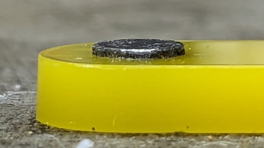
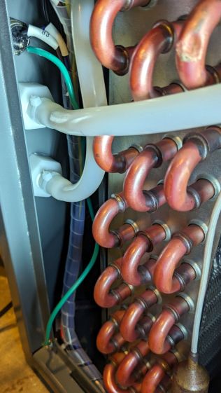
Remove the spicy pillow from an M20 battery case and carve a notch in one side to see if this might work:

The circuit board is the charge controller for the evicted high-voltage lithium pouch cell, but I started by connecting an ordinary lithium cell with a Schottky diode to the PCB’s battery terminals.
This worked about as poorly as you’d expect, because the lower battery voltage minus the forward drop of the diode minus whatever happens in the PCB put the final voltage below the camera’s instant low-battery shutdown.
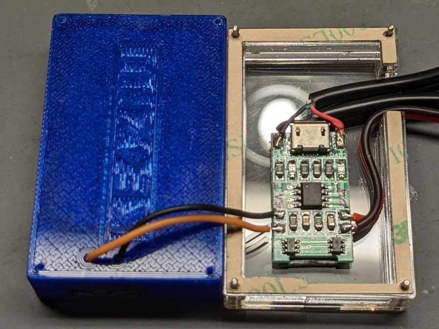
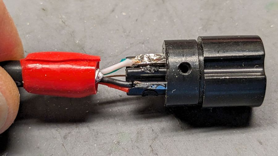
The terminals connecting to the camera in the rectangular bump are soldered to the back of the PCB, but the whole affair snaps out of the battery case. Unsoldering the PCB from the terminals, gingerly soldering directly to them, and adding a bulk storage capacitor produced a better result:
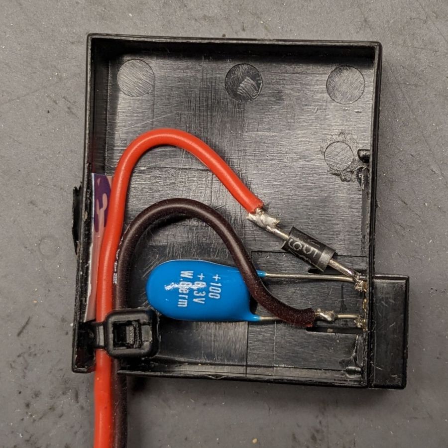
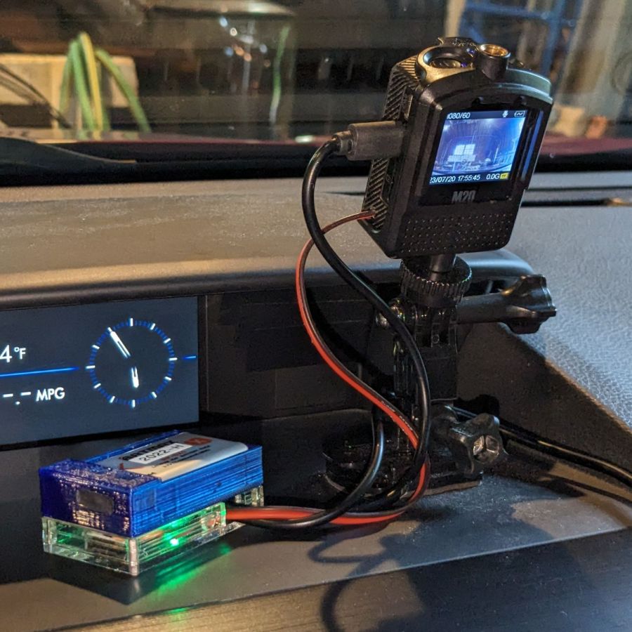
The cap stores just enough energy to keep the camera happy while writing to the Micro-SD card, although the LCD screen dims slightly during each pulse.
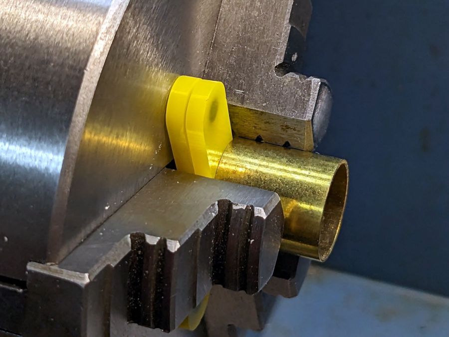
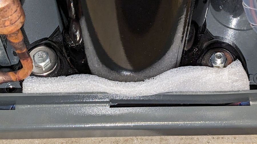
Cut a pad from a sheet of closed-cell foam that happened to be exactly the right thickness:
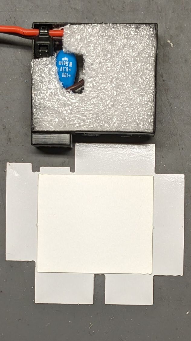
The elaborate thing below the case is a cardboard pad atop the sticky side of a PSA non-PVC vinyl sheet, laser-cut to fit:

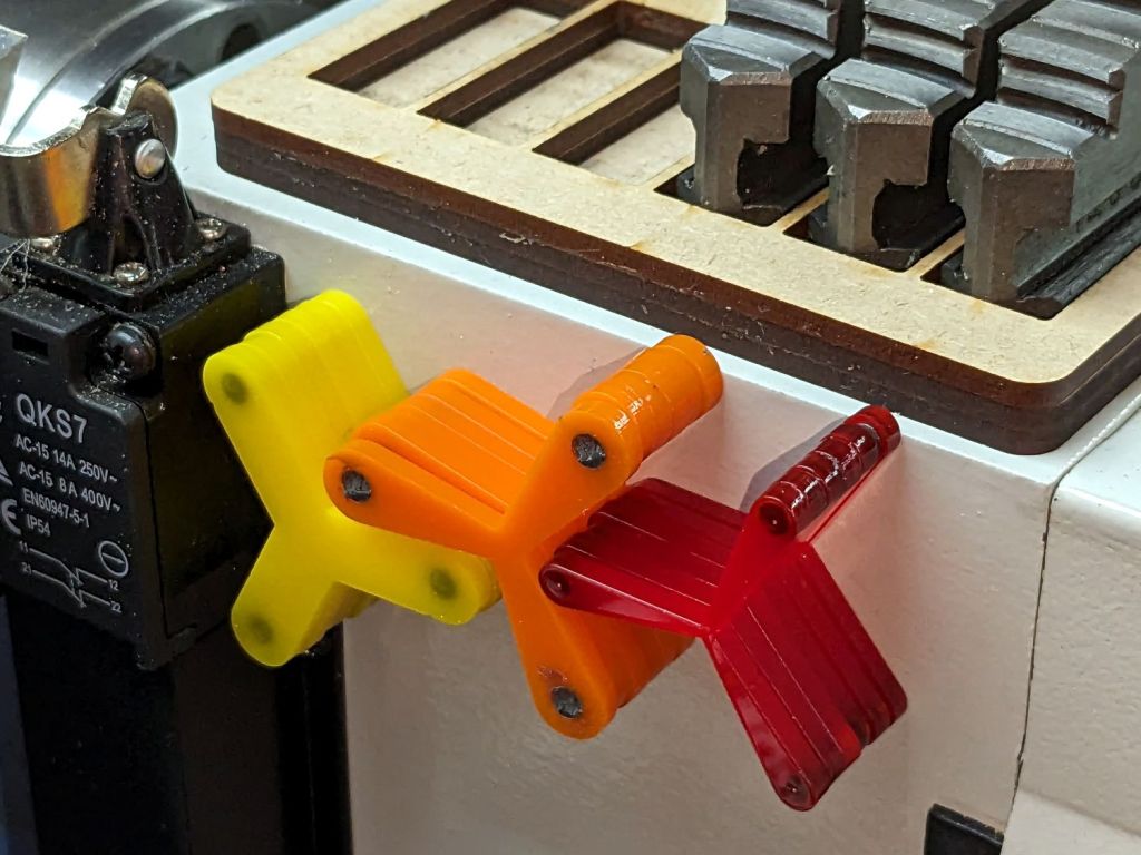
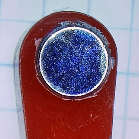
The bottom view, showing the latch retaining the contact block:

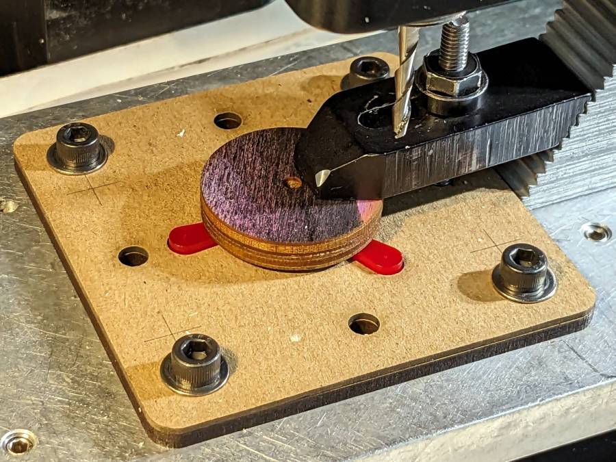
Admittedly, that’s the last iteration of the wrapper, starting with a hand-trimmed Kapton tape version and three paper versions to get the dimensions right before trying vinyl. Looks good to me!
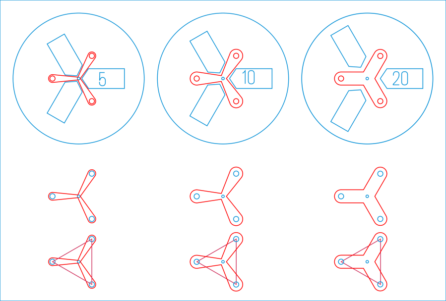
The final geometry has a 0.5 mm radius on all the corners:

The fillets reduced (but did not eliminate) mechanical oscillations while slinging the laser gantry around those corners. If I don’t point them out, maybe nobody will notice.
The PSA vinyl is marginally thicker than the original plastic wrapper, so the battery fits very snugly into the camera. On the other paw, getting the swollen battery out required a major effort; this one should not get tighter.


