A wood desk chair that I’ve known since I was a pup finally got some much-needed attention, although not a restoration. By and large, I’m finally sorting out that corner of the basement and needed to put the chair’s parts back together so I can work on something else.
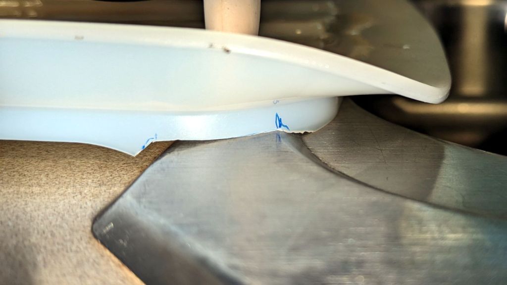
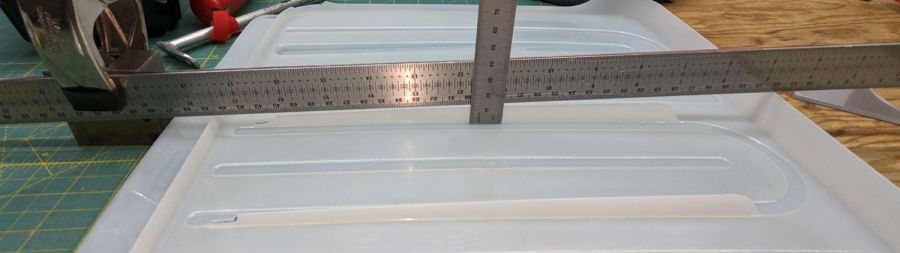
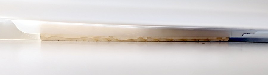
The wood seat consists of several slabs glued along keyed joints, one of which had fractured into a rough mess. Amazingly, the two sides fit perfectly together, albeit with the bottom no longer a planar surface, and glued up just like they should:
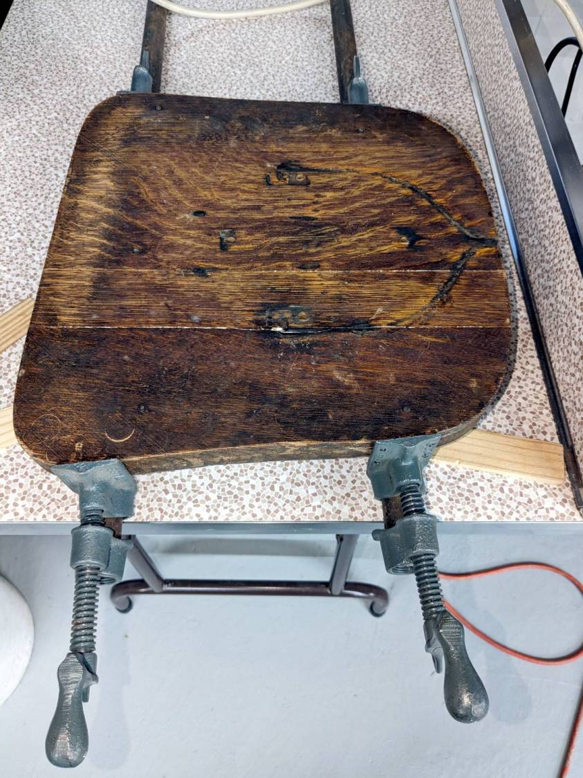
The chair isn’t up to contemporary office standards, but it has a seat elevation screw, a backrest with adjustable angle & elevation, and even a backrest tension setting:

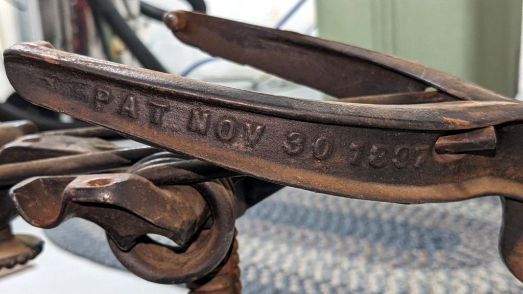
It was the cutting edge of desk chair technology:

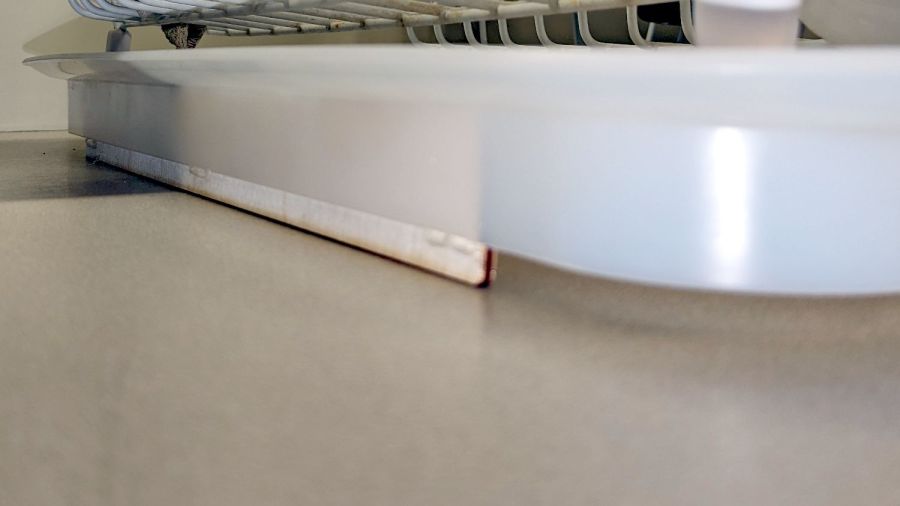
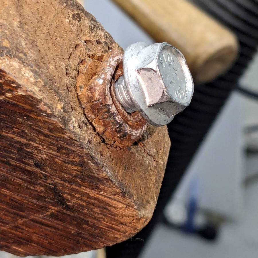
I vaguely recall it rolled on long-vanished steel-wheeled casters. Somewhat less long ago, one of the legs broke enough to lose its caster socket (about which, more later), so I set about yanking the three remaining sockets:
During that struggle, another leg revealed a neat woodwork joint:
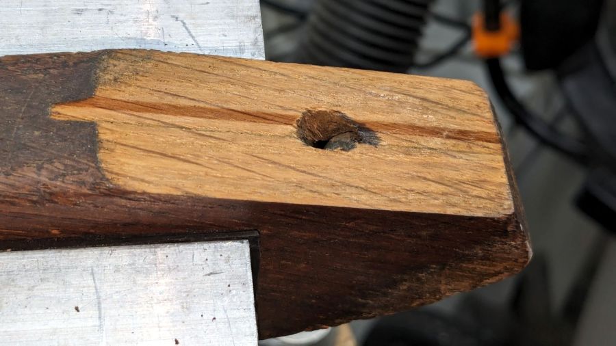
It’s easy to remove a caster socket when you can bash it from the top!
Gluing that piece back in place required Too Many Clamps™ aligning it with the leg:
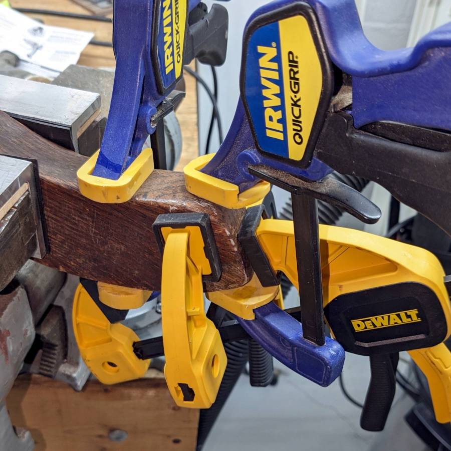
But the end result looks pretty good:
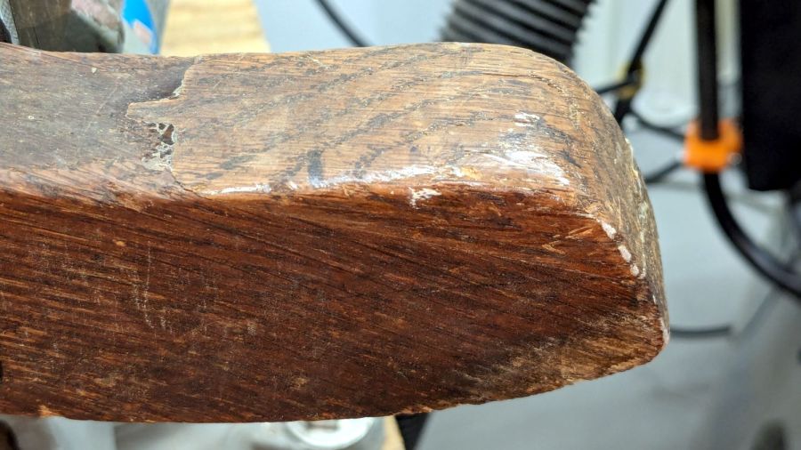
They did a nice job of matching the wood grain; I hadn’t noticed that joint while attacking the socket.
Pending restoring the broken leg’s socket, the soon-to-arrive new casters will clash horribly with the chair’s woodwork. At least it’ll roll again and its new plastic wheels won’t scar the floors.