Ed Nisley's Blog: Shop notes, electronics, firmware, machinery, 3D printing, laser cuttery, and curiosities. Contents: 100% human thinking, 0% AI slop.
Tag: Improvements
Making the world a better place, one piece at a time
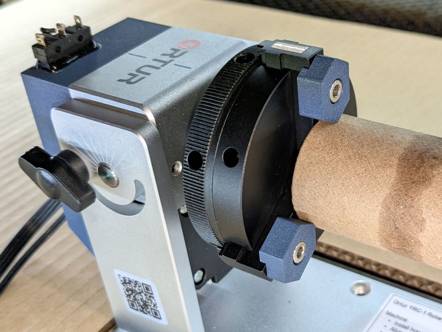
Whereupon the tube remains nicely tubular on both ends and aligned along the chuck axis:
Ortur YRC-1 – chucked cardboard tube
Which is why you save all that scrap material …
Yes, it’s the core from a toilet paper roll, which is way cheaper than burning through tumblers / mugs / shot glasses / whatever while figuring this stuff out.
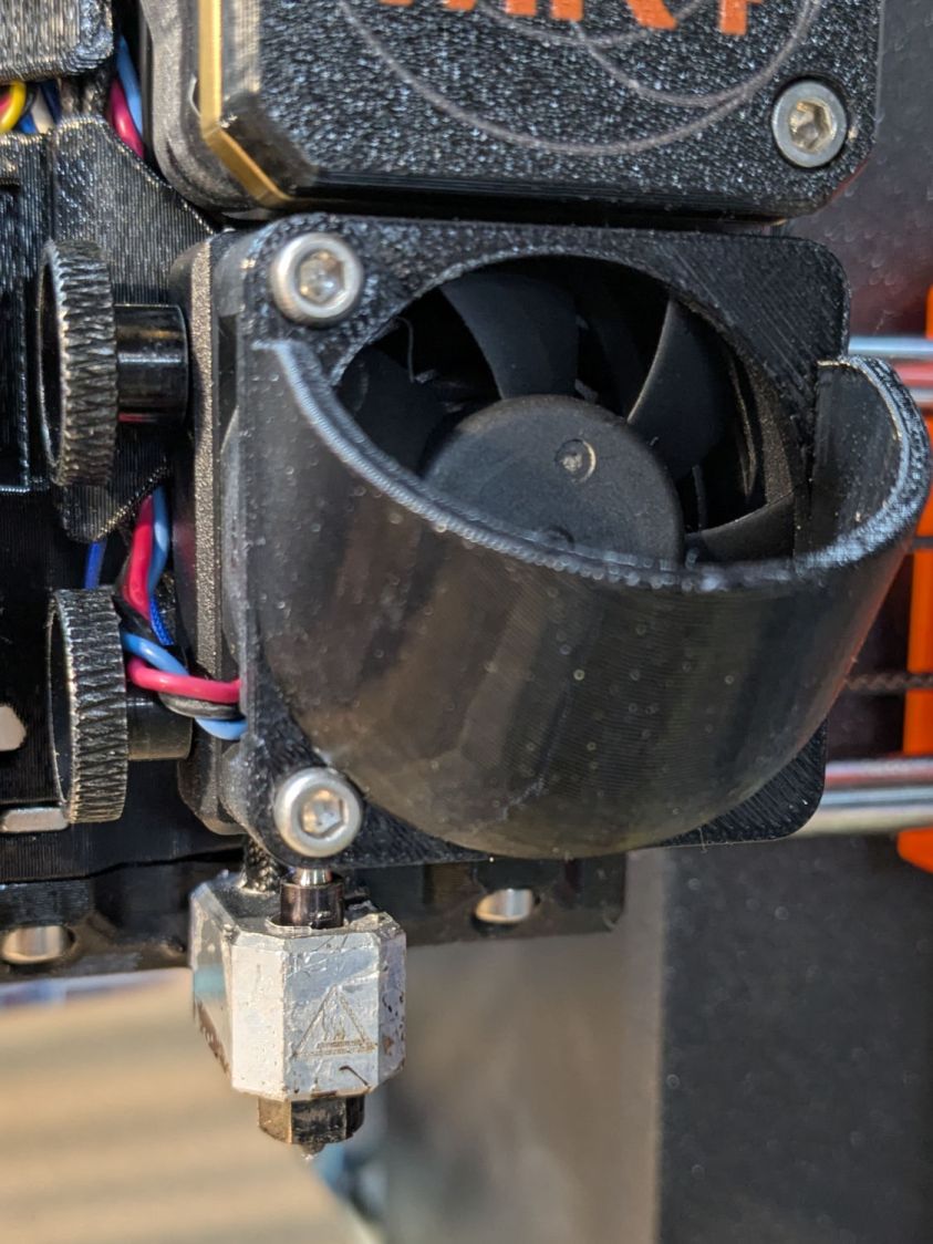
For obvious reasons, it doesn’t fit with the inlet scoop I installed as part of blinging the MK4:
Prusa MK4 Nextruder Tool – inlet scoop installed
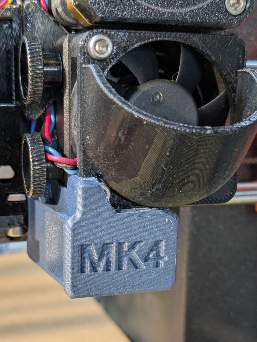
Removing the scoop is a matter of removing those two cap screws, which is no big deal, but a little flush-cutter action made that problem Go Away forever:
Prusa MK4 Nextruder Tool – inlet scoop mod
Yeah, I should have modified the solid model. Maybe next time.
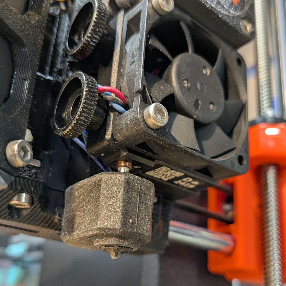
A version of the tool fits extruders covered with an Official Prusa Silicone Sock thermal insulator, but they were out of stock when I was in the mood. My heater wears a knockoff sock:
Prusa MK4 Nextruder Tool – silicone sock vs nozzle
Unlike the Official Sock, there’s no way to get a wrench on the nozzle with that one installed, but removing the sock is no big deal.
I apparently installed the nozzle / heater block slightly higher than specified, so the tool didn’t quite fit. Loosening those two thumbscrews and lowering the nozzle to fit the tool solved that problem. Fortunately, the automatic bed leveling routine corrects for nozzle height differences on the fly.
The scoop is back on the fan, the sock once again surrounds the heater, and I can easily swap in the 0.8 mm nozzle when the time comes.
We buy olive oil in large bottles, then fill smaller bottles for easier handling. The caps on those bottles were never meant to last as long as we keep them and the thin, deeply drawn aluminum tends to crack after a while.
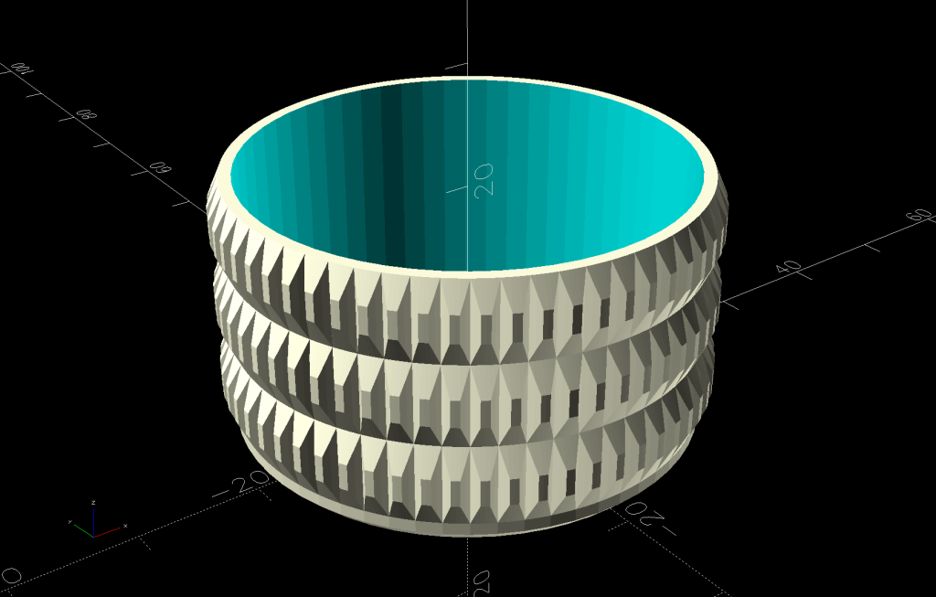
So I conjured a cap cover from the vasty digital deep:
Olive Oil Cap – solid model
Which looks exactly like you’d expect when printed in black PETG:
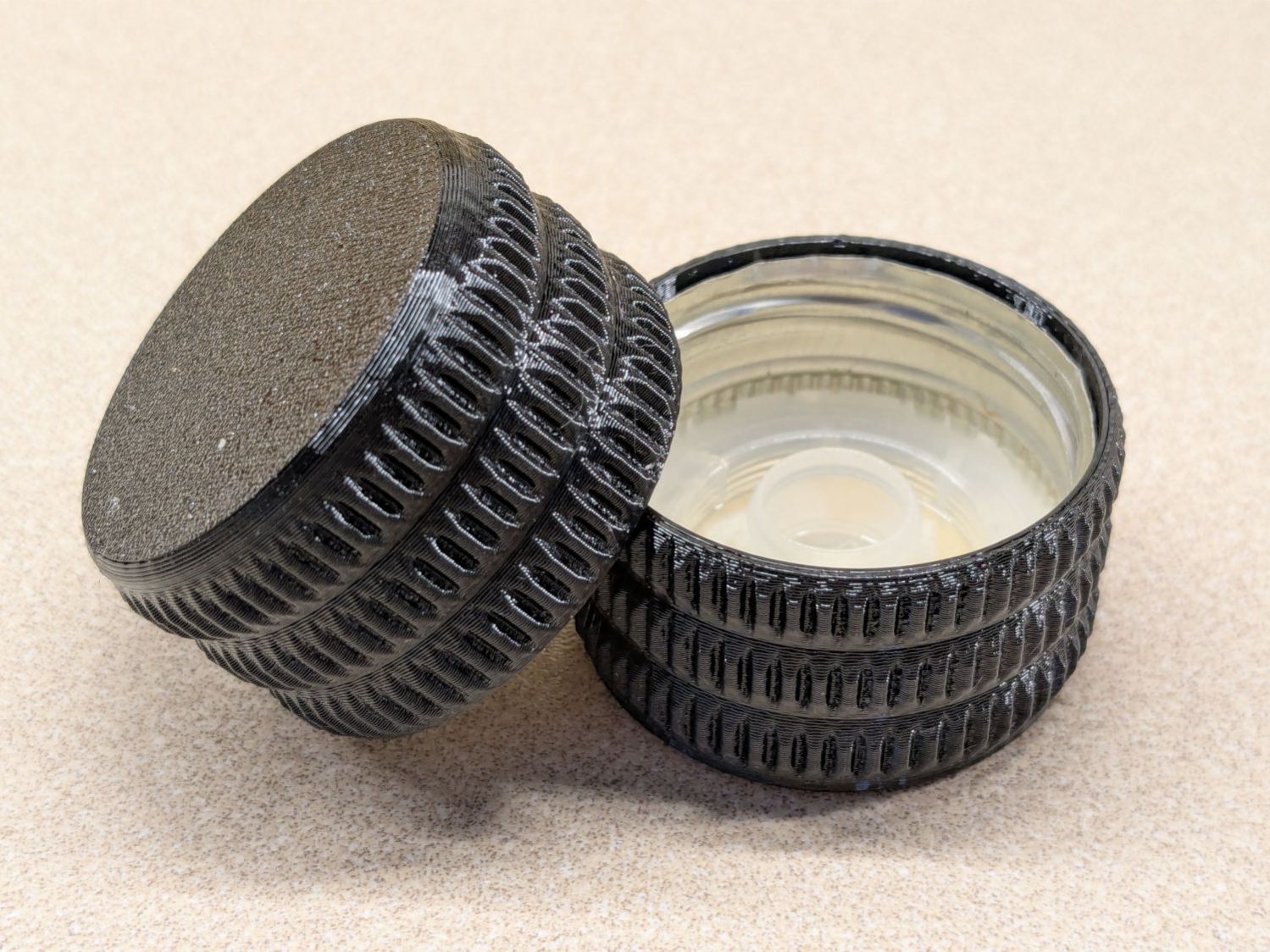
Olive oil bottle cap – details
You can see the raggedy edge of the original cap just inside the cover’s rim. A snippet of double-sided tape holds the cover in place, after de-oiling the cap with alcohol.
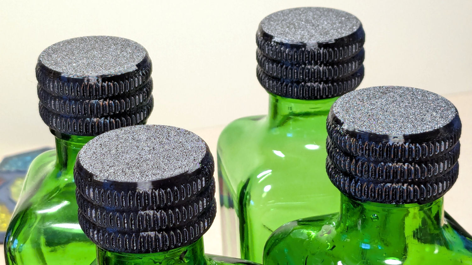
Having gotten one to fit, I made enough for All The Bottles:
Olive oil bottle cap – installed
Only two of those see regular service: one in use and another filled when the first is nearly empty. The remaining pair huddle in the back of the shelf against future need.
Always disable the rotary’s stepper driver before connecting or disconnecting its cable.
The Ortur YRC-1 rotary has a pulley ratio of 1:3, so the step/rev value is three times the DIP switch setting on the stepper driver. For this setup, 1600 → 4800 step/rev.
The honeycomb frame is a parallelogram, not a rectangle. I align the cardboard baffle / fixture to the bottom edge of the frame and the rotary to the bottom edge of the fixture opening, but your machine will be different. The angular alignment may not be off by enough to matter, but consistency is a virtue.
The Rotary.lbset and Linear.lbset files live on a file server with daily backups. Such backups will come in handy when you inadvertently overwrite one of those files with the other one. Trust me on this.
The Rotary.lbset file does not have Rotary Mode enabled, because the KT332N does not home the Y axis in that mode. If your rotary lacks a home switch, then it doesn’t matter and you’re on your own.
The KT332N controller has a [Reset] button that allegedly does a power-on reset and reloads all the changed Machine Settings. This sometimes does not work as expected: power-cycling the controller is the only way to be sure.
The autofocus operation must hit the focus pad, which can be ensured by positioning the pen near the pad, jogging the platform a few millimeters under the pen, tweaking X and the gantry while peering down parallel to the pen, then doing the autofocus.
The focus pad has a crosshair clearing the chonky Ortur 3-step jaws, but I set the controller’s [Origin] at the foot of the pad’s base for more elbow room.
The Z axis distance field in LightBurn’s Move window does not accept formulas, so you must divide the workpiece diameter by two. Using a focus stick to verify the ensuing nozzle-to-workpiece distance is a Good Idea™.
The LightBurn Job Origin dot must be on the top row, because the KT332N does not go into regions with negative coordinates. With the chuck on the left and the [Origin] just to its right, the upper left dot locks the LightBurn selection to the physical limits.
Selecting [Use Selection Origin] puts the Job Origin at the upper left (per the dot) of whatever you’ve selected, not everything on the LightBurn workspace. [User Origin] then locks the selection to the [Origin] set on the controller.
A SquidWrench meeting discussion about printing transparent objects prompted me to conjure a soap dish from the vasty digital deep:
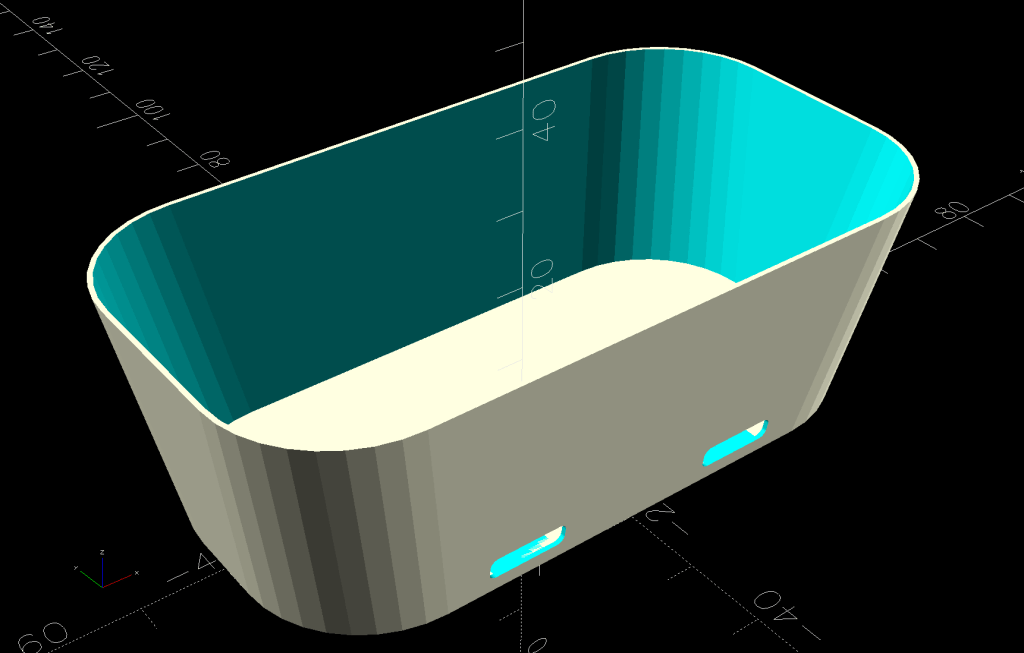
Shower Soap Dish – solid model
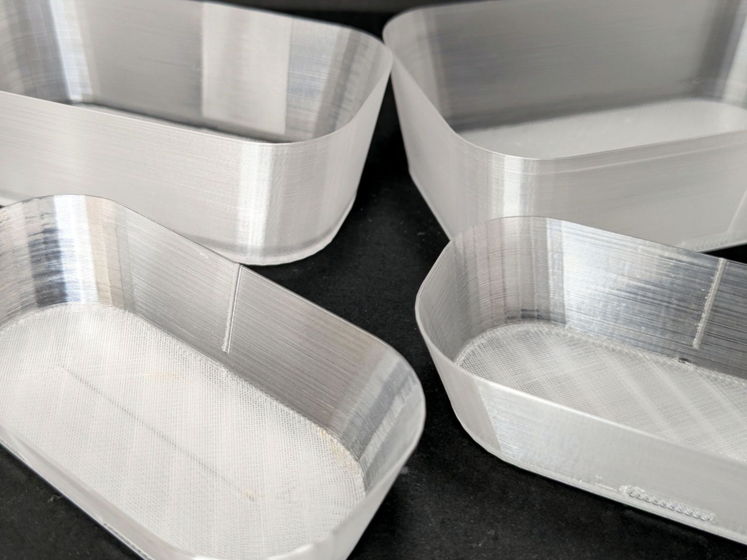
They’re all done in “natural” PETG with sufficient variations in speed, temperature, extrusion multiplier, and fill pattern to stock the shower & tub:
Translucent soap dishes
The single-thread sidewalls came out reasonably translucent in all the variations, but the baseplate remained stubbornly white-ish, even at 20 mm/s and 250 °C with 100% infill. The seams where the extruder retracts and lifts to the next layer remain conspicuous, with a scarf joint forming the white slab in the left-rear dish.
Quite a while ago, I’d considered making soap dishes with shattered-glass bottoms, but came to my senses. These have some key advantages:
Exactly the right size for narrow shower shelves
Light enough to not damage anything when it inevitably falls off
Reasonably unbreakable when that happens
Easily replaced
They’re also test pieces for the whole transparency thing, so it’s all good.
This file contains hidden or bidirectional Unicode text that may be interpreted or compiled differently than what appears below. To review, open the file in an editor that reveals hidden Unicode characters.
Learn more about bidirectional Unicode characters
The standard jaws for the Ortur Rotary loom over small-diameter workpieces:
Ortur Rotary Focus Pad – home offset adjustment
Some measuring and modeling produced petite 3D printed jaws:
Ortur Rotary – printed jaws
Admittedly, those jaws aren’t doing much of anything, but they’re not nearly as much in the way. You (well, I) can screw them in closer to the center to overlap the chuck jaws or another hole outward for slightly larger cylinders.
The solid model looks about the same:
Ortur Rotary Jaws – 2-3 show view
They build face-down with a little support under the screw recesses for a clean fit on the chuck:
Ortur Rotary Jaws – Prusaslicer
Teeny jaws might be handy:
Ortur Rotary Jaws – 2-2 show view
Screwing them in one hole outward lets them grip medium cylinders without sticking out from the chuck jaws:
Ortur Rotary – small printed jaws
The OpenSCAD code lets you pick which screw holes you want, but it does not error-check the perverse choices.
This file contains hidden or bidirectional Unicode text that may be interpreted or compiled differently than what appears below. To review, open the file in an editor that reveals hidden Unicode characters.
Learn more about bidirectional Unicode characters
Ruida laser controllers do not allow the platform to rise above the U=0 origin set by the autofocus pen = switch. While this isn’t a problem for flat surfaces, focusing on the exact top of a horizontal cylinder, particularly a small rod, may be overly difficult.
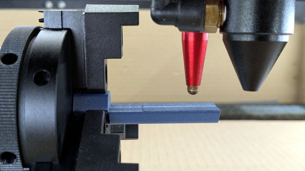
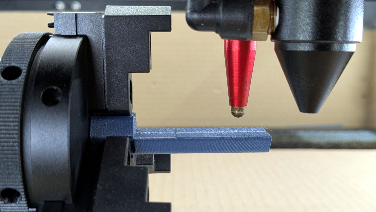
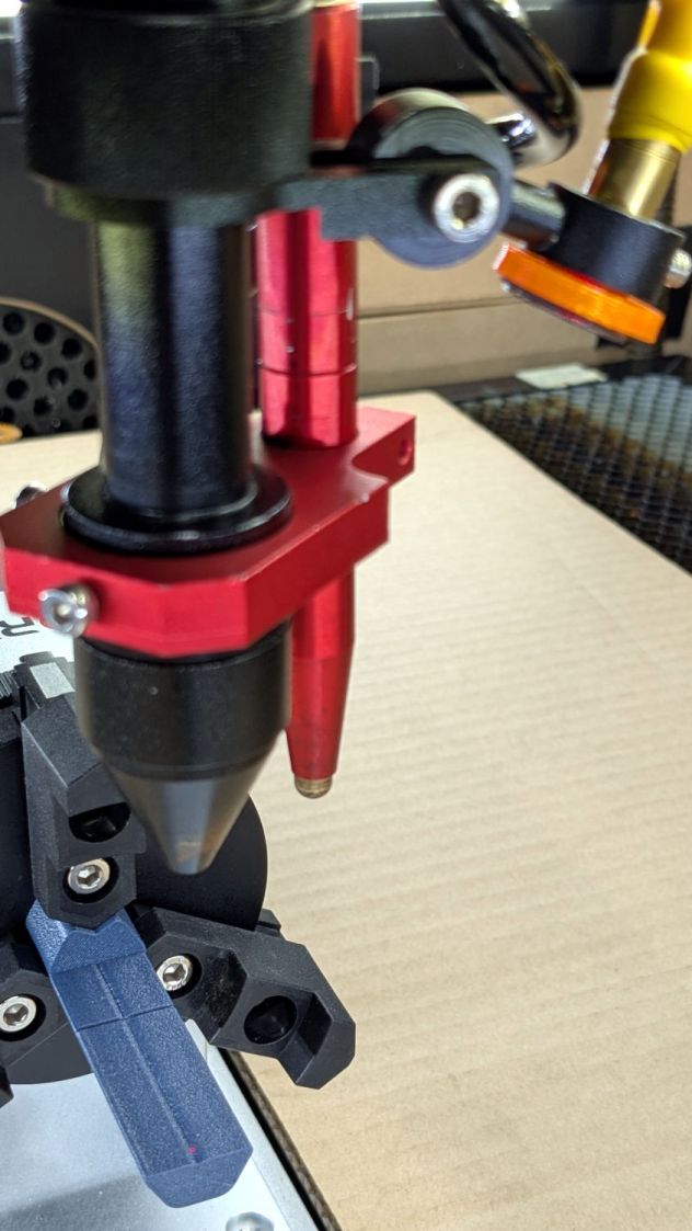
So a focusing pad seems like a Good Idea™:
Ortur Rotary Focus Pad – focus pen positioning
The general idea:
Align a flat horizontal surface with the rotary chuck’s axis
Do the autofocus operation with a well-defined landing zone under the pen
Jogging the head upward (= platform downward) by the workpiece radius puts the focused spot exactly at the right height
Remove the focus pad
Install the workpiece
Fire The Laser
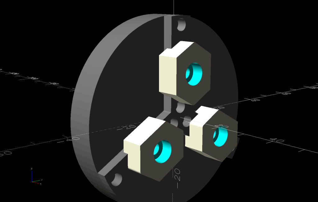
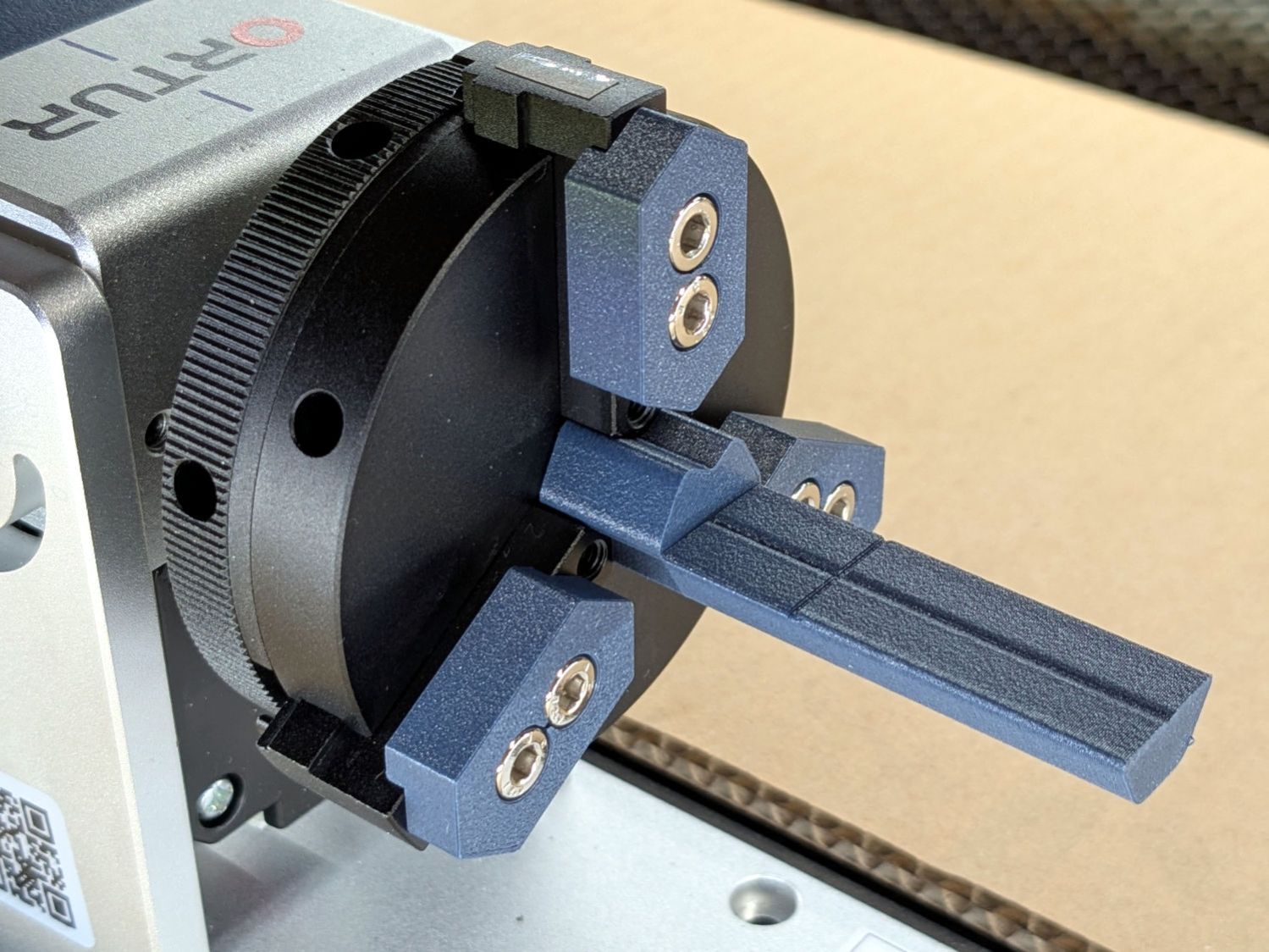
The solid model:
Ortur Rotary Focus Pad – solid model
Features of note:
The chuck jaws fit into the recesses on the left end for a firm grip with good alignment
The lengthwise notch lies on the rotary axis parallel to the laser’s X axis
The crosswise notch is juuust rightward of the chuck jaws, marking the leftmost end of whatever you’re engraving
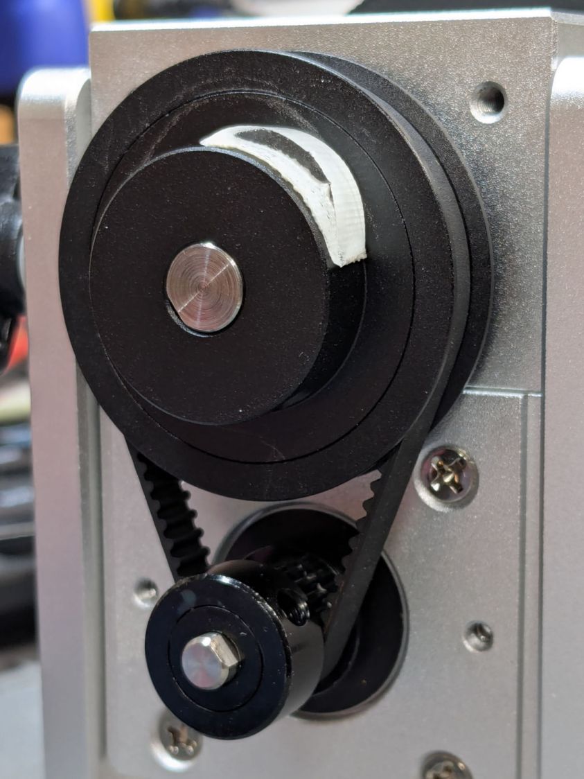
Because I added a home switch to the Ortur YRC-1 case, Jaw 1 automagically ends up on top after homing, thus automagically making the focus pad horizontal. Getting that right required fine-tuning the rotary’s home switch trip point, which turned out to be easier to do using the Home Offset configuration value after I replaced the cam I thought would work:
Ortur Chuck Rotary home switch – pulley cam
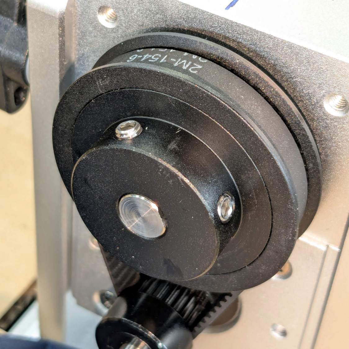
Instead, a simple M4 setscrew (standing proud of the pulley surface in one of the tapped holes for the real setscrew securing the pulley to the shaft) trips the switch much more repeatably :
Ortur Rotary Focus Pad – home trip setscrew
The setscrew on the right sits flush with the surface to prevent the switch roller from falling into the hole. The real setscrew underneath it locks the pulley to the shaft’s flat.
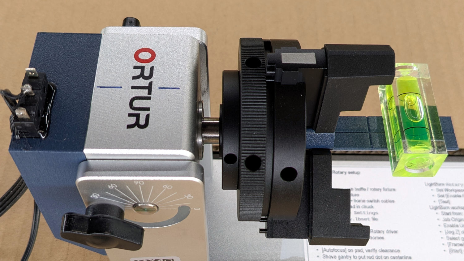
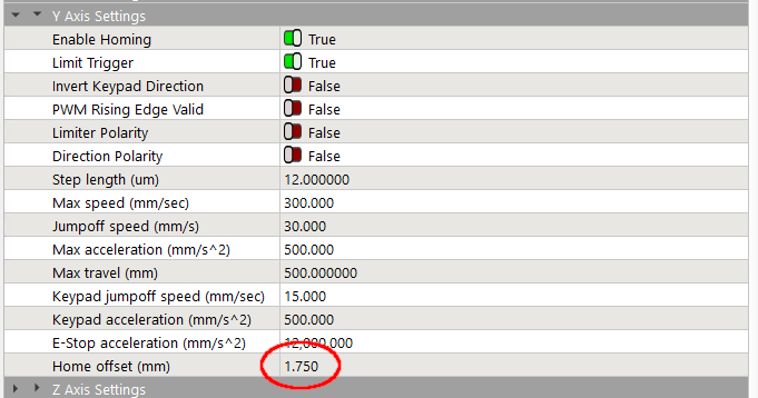
With that in place, a quick binary search settled on a Y axis Home Offset = 1.75 mm to put the pad level with the top of the rotary’s case, which is Level Enough™ due to my tweaking the machine’s foot elevations after jacking the whole machine up on risers:
Ortur Rotary Focus Pad – home offset adjustment
The Home Offset value:
The speed and acceleration values are much lower than used with the linear Y axis, because apparently Ruida computes the corresponding step values using the workpiece diameter in the Rotary section. Small diameters produce impossibly fast motions, which suggests they expect you to set the optimum values based on back-calculations from the object diameter; ain’t nobody got time for that.
Anyhow.
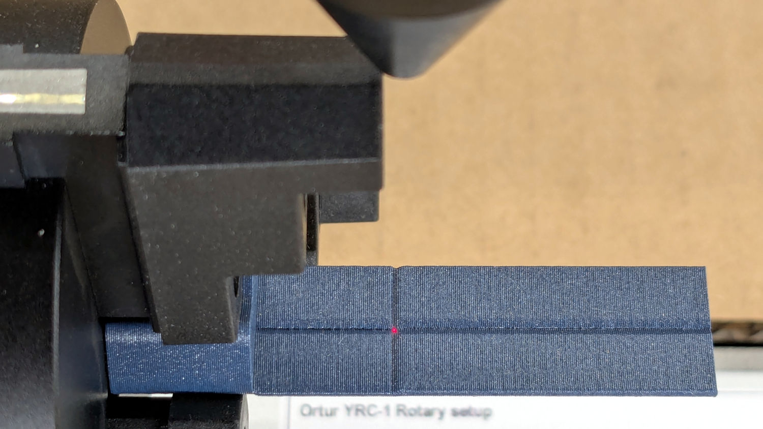
After autofocusing, the red-dot pointer now indicates the laser spot position, so jog the X axis and drag the gantry to put the spot on the axis mark:
Then jog the X axis to put the dot at the transverse mark just beyond the chuck jaws:
Ortur Rotary Focus Pad – red dot at origin
Hit the Ruida Origin button to set that as the user origin, so you can reference the LightBurn design to the hardware position.
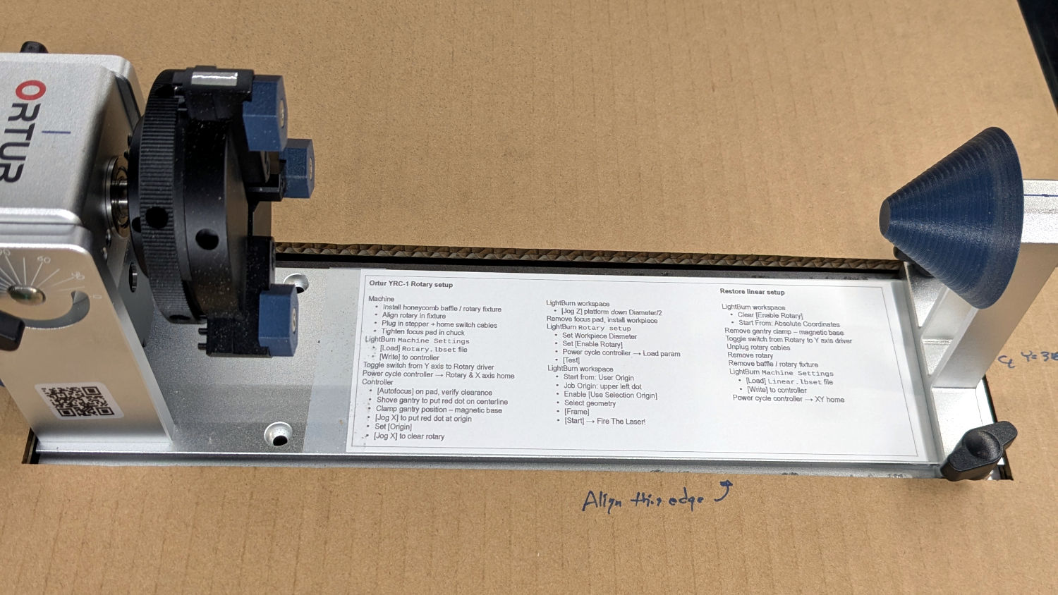
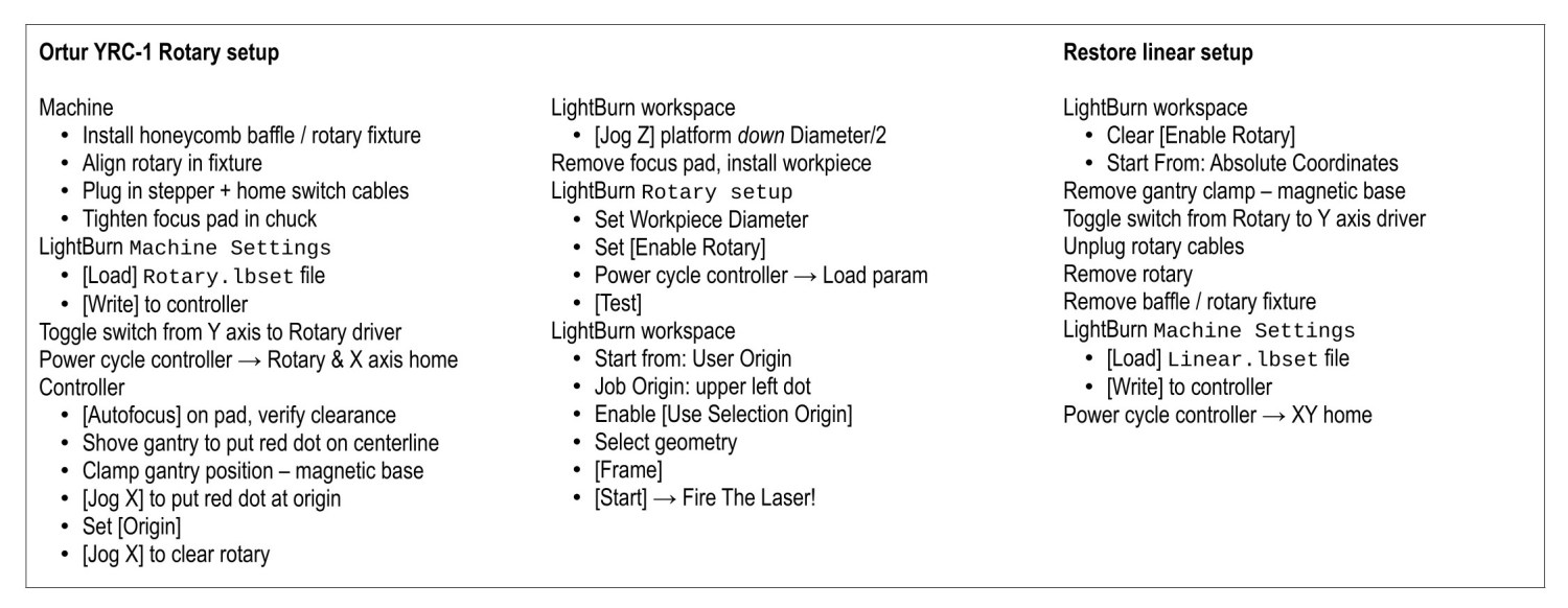
Move the platform down by the workpiece radius, jog the nozzle along the X axis to get it out of the way, remove the focus pad, install the workpiece, and you’re good to go. The checklist visible beyond the bubble level shows it’s not quite that simple, but we’re getting there.
This file contains hidden or bidirectional Unicode text that may be interpreted or compiled differently than what appears below. To review, open the file in an editor that reveals hidden Unicode characters.
Learn more about bidirectional Unicode characters