Ed Nisley's Blog: Shop notes, electronics, firmware, machinery, 3D printing, laser cuttery, and curiosities. Contents: 100% human thinking, 0% AI slop.
Tag: Improvements
Making the world a better place, one piece at a time
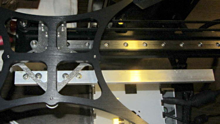
This overview shows the aluminum strut sticking out to the rear (Y+) end of the platform support spider:
HBP connector support strut – overview
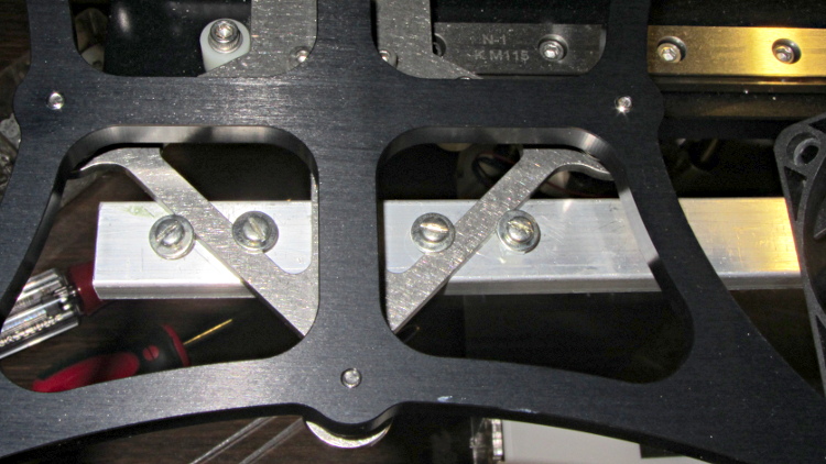
A closeup shows a quartet of 4-40 holes drilled and tapped along the strut’s midline:
HBP connector support strut – mounting detail
Admittedly, that’s a bit of a kludge, but I didn’t want to drill holes in that nice steel bracket… particularly since I’d have to dismantle the whole stage to get to it. The four screws wedge the strut firmly in position and have jam nuts on the bottom so they don’t loosen.
I extracted more wire from the braided sheath and moved the cable a bit further out at the cable tie holding it to the Y axis stage, then cable-tied the HBP connector to the strut.
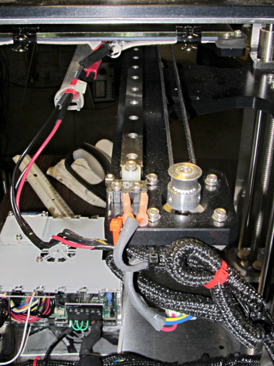
With the stage all the way to the rear:
HBP connector support strut – at Y min
And to the front:
HBP connector support strut – at Y max
The wires may break, but now the HBP connector and heating pad joints should survive!
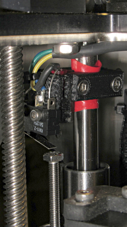
The printed bracket for the M2’s Z axis home switch doesn’t get a good grip on the oiled steel rod, so it can slide around just a little bit when nudged. That doesn’t happen often, but when it does, all your careful alignment Goes Away.
A single wrap of silicone tape solves that problem:
Z min switch on silicone tape
While I was in there, I replaced the socket-head cap screw I’d been using with a longer hex bolt and swapped the nylock nut for a plain nut that’s easier to adjust. I should file the raised markings off the top of the bolt head so it presents a smooth surface to the switch.
Dan sent me a Kysan 17HD-B8X300-A, a leadscrew-equipped stepper motor with much higher torque than the Makergear Z axis motor. According to the Kysan description, which is all we have to go on: 4.2 V @ 1.5 A means 2.8 Ω, at which current it produces 5.5 kg·cm = 540 mN·m of torque. I measure 3.2 Ω and 3.5 mH, not that that makes much difference.
I worked out some of the numbers in that post and, if they’re close, then the new motor has twice the torque of the OEM one. What’s more important is that the new motor will work correctly with a microstepping drive and won’t bake while doing so.
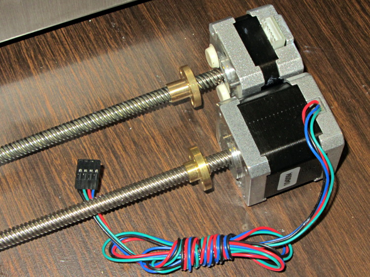
The new motor has more metal to it than the old one:
M2 Z Axis motors – OEM vs replacement
The leadscrew follower nut has unthreaded holes, but, mercifully, has the same OD, fits nicely into the Z stage, and those four holes line up perfectly.
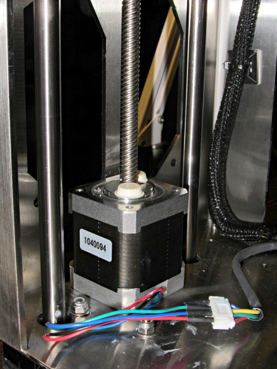
I chopped off most of the wires and spliced a JST plug onto the end; of course, the motor ran backwards. Having foreseen that eventuality, I had not shrunk the tubing over the wires: swap a pair, shrink the tubing, and it’s done:
M2 Z Axis motor replacement
Some notes from the operation:
Disconnect all the cables
Remove HBP + glass plate
Lay printer on +X side of the chassis
Remove screws holding Z motor to chassis
Remove nylock nuts and screws from leadscrew follower nut
Remove Z axis home switch
Run Z stage to top of rods
The leadscrew bearing will probably have fallen out by now
Loosen Z rod clamp nuts & bolts (top & bottom of rods)
Push Z rods out using a nut driver, pull with a rag for traction
Be ready to catch the Z stage when you remove the rods!
Angle motor & leadscrew out of the chassis
Angle new motor & leadscrew into the chassis
Reinstall everything in reverse order
Recalibrate everything…
The Z rod sliders have little balls inside, but they didn’t fall out during this adventure. I don’t know if that’s reliable information or not.
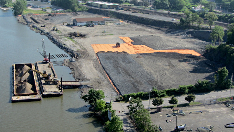
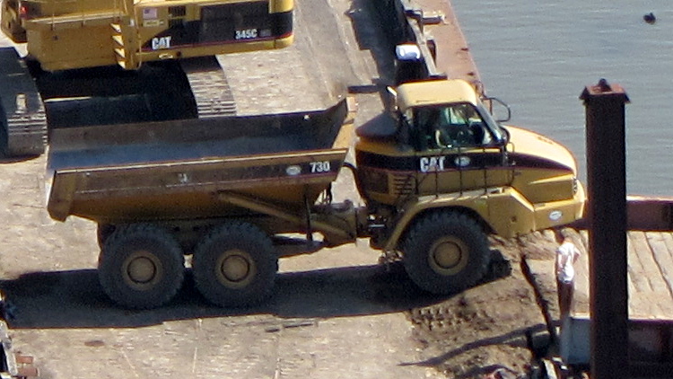
Back in the day, long before the environmental movement got any traction, the Poughkeepsie waterfront along the Hudson River used to be an industrial hotbed. That tapered off and, after a while, only the Dutton Lumber treatment facility remained; they manufactured classic CCA pressure-treated lumber. Quite some years after (IIRC) they went bankrupt and abandoned the facility, various buildings burned and the site seems to be slated for redvelopment into condos and suchlike.
The wisdom of siting condominiums along a tidal estuary, just a few meters above the current waterline and well below the future projected flood stage, seems dubious to me, but, then, I’m not a developer.
Anyhow, a recent ride across the Walkway showed that they’re sealing off the contaminated soil under what was once the lumberyard:
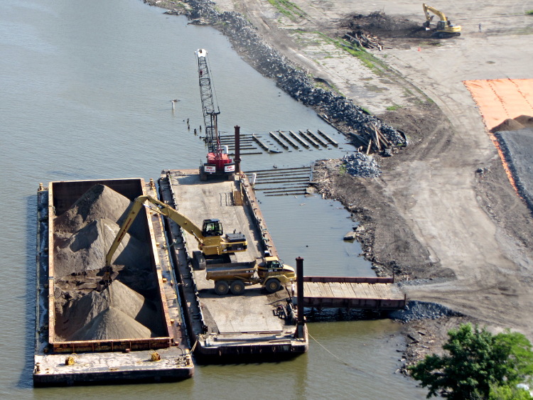
An excavator moves gravel from the barge, which probably came a few miles upriver (or downriver, depending on the aforementioned tidal flow) from the Tilcon quarry at Clinton (no relation) Point, into the dump trucks:
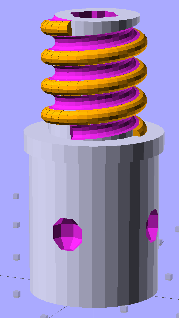
Although I don’t need another threaded plug, the most recent OpenSCAD version can handle a model including the thread dedendum:
Broom Handle Screw – full thread – solid model
This hyper-close view (as always, clicky for more dots) shows the problem: the region where the addendum and dedendum meet at the pitch cylinder consists of a bazillion tiny faces:
Broom Handle Screw – full thread – detail
The previous version simply couldn’t handle that many elements, but the new version has a parameter that I tweaked (to 100,000), allowing it to complete the rendering. Compiling to a solid model requires about 45 minutes, most of which probably involves those unprintably small facets.
The thread elements now taper slightly in the downhill direction, so that each quasi-cylinder nests cleanly inside the next to avoid the tiny slivers that stuck out of the joints in the previous model.
And the new Slic3r version (from GitHub) has better internal support for those indentations around the base, which means that AC vent plug might be build-able, too.
The OpenSCAD source code, with a few tweaks to nest the thread cylinders and properly locate the dedendum:
// Broom Handle Screw End Plug
// Ed Nisley KE4ZNU June 2013

//- Extrusion parameters must match reality!
//  Print with 2 shells and 3 solid layers

HoleWindage = 0.2;

Protrusion = 0.1;			// make holes end cleanly

//----------------------
// Dimensions

PostOD = 22.3;				// post inside metal handle
PostLength = 25.0;

FlangeOD = 24.0;			// stop flange
FlangeLength = 3.0;

PitchDia = 15.5;			// thread center diameter
ScrewLength = 20.0;

ThreadFormOD = 2.5;			// diameter of thread form
ThreadPitch = 5.0;

BoltOD = 7.0;				// clears 1/4-20 bolt
BoltSquare = 6.5;			// across flats
BoltHeadThick = 3.0;

RecessDia = 6.0;			// recesss to secure post in handle

OALength = PostLength + FlangeLength + ScrewLength;

$fn=8*4;					// default cylinder sides

echo("Pitch dia: ",PitchDia);
echo("Root dia: ",PitchDia - ThreadFormOD);
echo("Crest dia: ",PitchDia + ThreadFormOD);

Pi = 3.14159265358979;

//----------------------
// Useful routines

// Wrap cylindrical thread segments around larger plug cylinder

module CylinderThread(Pitch,Length,PitchDia,ThreadOD,PerTurn=32) {

CylFudge = 1.02;				// force overlap

    RotIncr = 1/PerTurn;
    PitchRad = PitchDia/2;

    Turns = Length/Pitch;
    NumCyls = Turns*PerTurn;

    ZStep = Pitch / PerTurn;

    HelixAngle = atan(Pitch/(Pi*PitchDia));
    CylLength = CylFudge * (Pi*(PitchDia + ThreadOD) / PerTurn) / cos(HelixAngle);

	for (i = [0:NumCyls-1]) {
		assign(Angle = 360*i/PerTurn)
			translate([PitchRad*cos(Angle),PitchRad*sin(Angle),i*ZStep])
				rotate([90+HelixAngle,0,Angle])
					cylinder(r1=ThreadOD/2,
							r2=ThreadOD/(2*CylFudge),
							h=CylLength,
							center=true,$fn=12);
	}
}

module PolyCyl(Dia,Height,ForceSides=0) {			// based on nophead's polyholes

  Sides = (ForceSides != 0) ? ForceSides : (ceil(Dia) + 2);

  FixDia = Dia / cos(180/Sides);

  cylinder(r=(FixDia + HoleWindage)/2,
           h=Height,
	   $fn=Sides);
}

module ShowPegGrid(Space = 10.0,Size = 1.0) {

  Range = floor(50 / Space);

	for (x=[-Range:Range])
	  for (y=[-Range:Range])
		translate([x*Space,y*Space,Size/2])
		  %cube(Size,center=true);

}

//-------------------
// Build it...

ShowPegGrid();

difference() {
    union() {
        cylinder(r=PostOD/2,h=PostLength);
        cylinder(r=PitchDia/2,h=OALength);
        translate([0,0,PostLength])
            cylinder(r=FlangeOD/2,h=FlangeLength);
        color("Orange")
        translate([0,0,(PostLength + FlangeLength)])
            CylinderThread(ThreadPitch,(ScrewLength - ThreadFormOD/2),PitchDia,ThreadFormOD);
    }

    translate([0,0,-Protrusion])
        PolyCyl(BoltOD,(OALength + 2*Protrusion),6);
    translate([0,0,(OALength - BoltHeadThick)])
        PolyCyl(BoltSquare,(BoltHeadThick + Protrusion),4);

    translate([0,0,(PostLength + FlangeLength + ThreadFormOD/2)])
		rotate(-90)
        CylinderThread(ThreadPitch,ScrewLength,PitchDia,ThreadFormOD);

	for (i = [0:90:270]) {
		rotate(i)
			translate([PostOD/2,0,PostLength/2])
				sphere(r=RecessDia/2,$fn=8);
	}
}
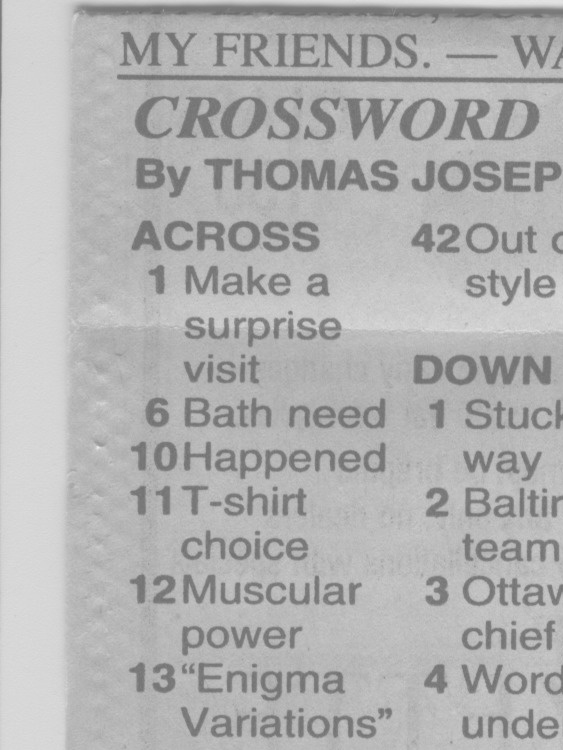
Mary’s folks enjoy the daily crossword, but they wanted a slightly larger edition… and, after a bit of procrastination, I conjured up an automated way to make it happen, so her father need not do this manually with The GIMP and Xsane.
The scanner, an old HP Scanjet 3970, dropped off the Windows driver list after Vista, so it now runs only with Linux.
Doing the scan is straightforward, as it’s the default scanner:
The X and Y coordinates set the scan dimensions in millimeters, which should be as small as possible consistent with scanning the whole crossword.
The driver produces output image files in PNM format, which isn’t particularly common these days, or TIFF. ImageMagick knows what to do with both of them; I picked PNM.
Unfortunately, for some unknown reason, the SANE driver produces a severely low-contrast image:
HP3900 Grayscale Scan
ImageMagick can produce a histogram:
convert scan.pnm histogram:hist.png
Which shows the problem:
HP3900 Grayscale Histogram
That’s using the grayscale emulation mode: the driver does a Color scan and converts to Gray mode for the output image. It seems having the driver do the conversion produces better results than scanning directly in Color and then applying ImageMagick, but it’s not my scanner and I don’t have a lot of experience with it.
This being Linux, the best way to print something is with either Postscript or PDF. I used PDF, because then we can look at the results with Reader, a more familiar program than, say, Evince:
Which centers the crossword on the page over a white background with enough margin to keep the printer happy:
Crossword – full page
That PDF goes to the default printer queue, where it’s turned into Postscript and comes out exactly like it should:
lp page.pdf
I gimmicked the default printer instance to use only black ink by creating a separate CUPS printer with the appropriate defaults. Other programs pay no attention to that setting and the printer uses colored inks. There is no explanation I can find for any of this; Linux / CUPS printing is basically a black box operation.
In theory, you could print the composited image file as a PNG or some such, but I cannot make it come out the right size in the right place.
You could do all of that in one line, with one huge ImageMagick invocation kicking off the scan and firing the result to the printer, but leaving some intermediate results lying along the trail isn’t necessarily a Bad Thing. I should probably use random temporary file names, though, in the interest of not polluting the namespace.
All this happened remotely, with me signed on through SSH: hooray for the command line. Had to use SCP a few times to fetch those intermediate files to puzzle over the results, too.
A while back I bought a lifetime supply of silica gel beads from Sorbent Systems, with the intent of gradually replacing all of the miscellaneous desiccant packs floating around here. The catch is figuring out how to package 2 mm spherical beads, because the whole point of a desiccant pack is getting moist air in contact with the beads. I’m sure there’s a commercial solution for this out there, but …
Anyhow, here’s what 500 g of beads looks like, captured inside a 12×12 inch square of landscaping cloth folded in half:
Silica gel in landscape cloth bag
It really should be sewn along the three joined edges, but this is a quick-and-dirty prototype to see how it works; I simply folded the edges over twice and stapled through all six layers.
For the record, 500 g of beads occupies 700 ml in the measuring cup I used to weigh and pour them into the end of the bag. The bag + beads + staples weighs 508 g. The can holding the bulk beads has a humidity indicator card that shows the humidity is below 10%, so I’ll assume they’re pretty well dehydrated.
It’s now in the basement safe, presumably soaking up moist air at a frantic pace. I’ll check it in a week or two and see what’s actually happening.
For the record, those old desiccant granules (and their tray) weighed 853 g when they went into the safe and emerged at 916 g, having soaked up 63 g = 2 oz of water over the last five months.