Ed Nisley's Blog: Shop notes, electronics, firmware, machinery, 3D printing, laser cuttery, and curiosities. Contents: 100% human thinking, 0% AI slop.
Tag: Improvements
Making the world a better place, one piece at a time
After replacing the front wheel bearings, I replaced both pairs of brake pads. The rear brakes use holders with slide-in pads, but I’ve never been happy with the dinky little pins that retain the pads, so this time I’m using ordinary cotter pins:
V-brake pads – cotter pin retainer
The rear brake pads on a diamond-frame bike sit nearly horizontally on the seat stays, with the pin head pointed upward. On Tour Easy recumbents, the pads stand almost vertically on the chain stays, with the pins sideways:
Tour Easy rear brakes
That photo dates to 2010, when those brakes were new. Nary a pin has worked loose yet and I don’t expect they ever will, but …
If the pins rust before the pads wear out, I’ll go back to those little bitty OEM stainless pins.
The Sony HDR-AS30V camera lens has a view angle of 120° or 170°, achieved by internal image processing rather than mechanical lens adjustments. For most action-camera purposes you don’t care about fisheye distortion, but sometimes a more rectilinear picture will look better, in which case the GIMP’s Lens Distortion filter comes in handy.
A still image at 120°, which doesn’t look all that bad, really:
Sony HDR-AS30V 120 angle – as captured
Applying Main=-25 gives this:
Sony HDR-AS30V 120 angle – corrected
A frame captured from video at 170°, with the overhead wires hanging upward:
Sony HDR-AS30V 170 angle – as captured
Applying Main=-25, Edge=-12.5, Zoom=+8 flattens them enough to be acceptable:
Sony HDR-AS30V 170 angle – corrected
The main effect of the Zoom parameter seems to be discarding the severely distorted remnants around the edges of the corrected 170° view. Sometimes, those pixels around the edges can be very, very important, so I’d rather make that decision after the fact.
As I recall, a few weeks after I bought this packing tape dispenser, I dropped it with the nut downward, whereupon all six of the little tabs that were supposed to hold the tape roll in place broke off, allowing the roll to walk off the holder. Having put up with that for far too long (I don’t do a lot of shipping these days), I finally drilled and tapped three 4-40 holes and ran a trio of setscrews against the inside of the roll core:
Packing tape dispenser – improved spool holder
The holes are angled so that the setscrews bite into the core just enough to prevent it from walking away, but I can still pull the roll off when it’s empty.
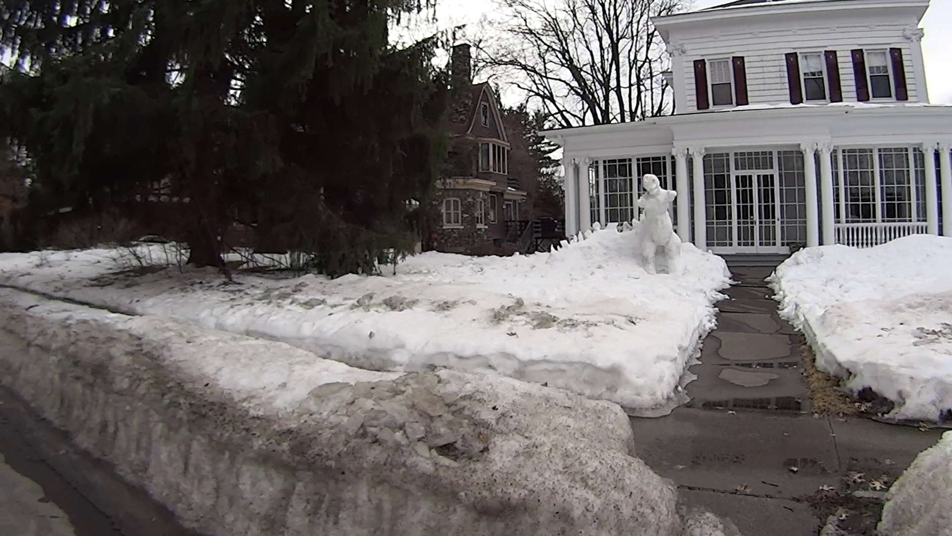
Natural PLA provides a nice, crystalline appearance:
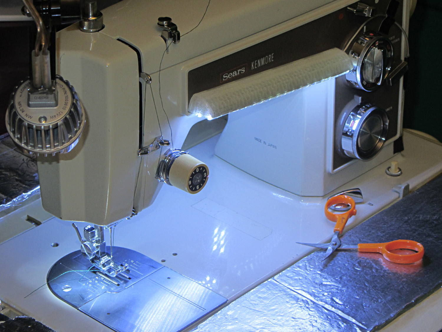
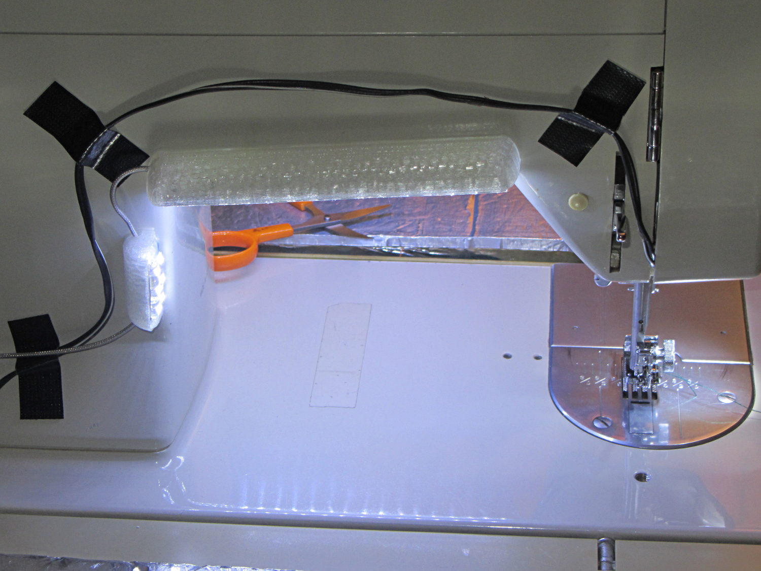
Kenmore 158 Sewing Machine – Cool white LEDs – rear no flash
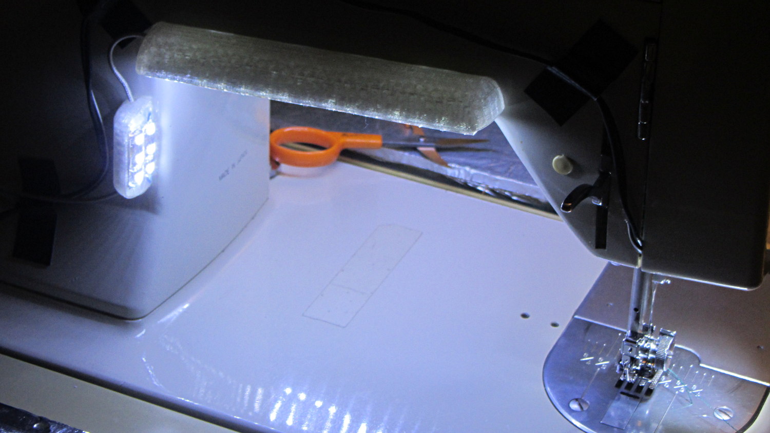
Cool white LEDs have somewhat higher lumen/watt efficiency, but the real gain came from doubling the number of LEDs:
Kenmore 158 Sewing Machine – Cool white LEDs – front flash
I overvolted the warm white LEDs to 14 V to get closer to 20 mA/segment, but the cool white ones run pretty close to 20 mA at 12 V, so I didn’t bother.
Commercial versions of this hack secure the wiring with little white clips and foam tape, so I should conjure up something like that. Mary specifically did not want the lights affixed under the arm, though, so those things weren’t even in the running.
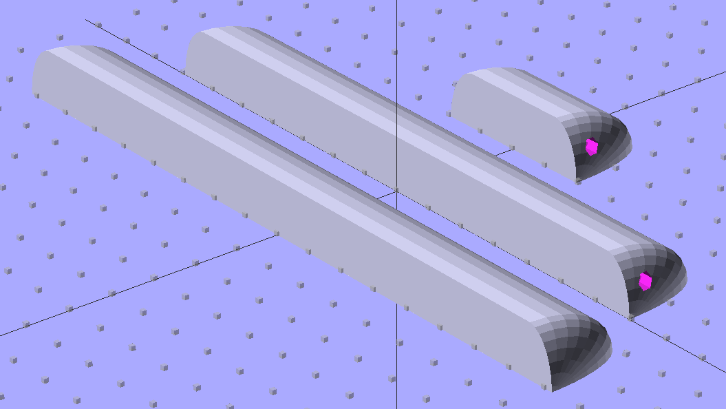
The OpenSCAD source code widens the mount and moves the wiring conduit a little bit, to simplify the connections to both strips, but is otherwise identical to the earlier version:
// LED Strip Lighting Brackets for Kenmore Model 158 Sewing Machine
// Ed Nisley - KE4ZNU - March 2014

Layout = "Build";			// Build Show Channels Strip

//- Extrusion parameters must match reality!
//  Print with 2 shells and 3 solid layers

ThreadThick = 0.20;
ThreadWidth = 0.40;

HoleWindage = 0.2;			// extra clearance

Protrusion = 0.1;			// make holes end cleanly

AlignPinOD = 1.70;			// assembly alignment pins: filament dia

inch = 25.4;

function IntegerMultiple(Size,Unit) = Unit * ceil(Size / Unit);

//----------------------
// Dimensions

Segment = [25.0,10.0,3.0];		//  size of each LED segment
SEGLENGTH = 0;
SEGWIDTH = 1;
SEGHEIGHT = 2;

WireChannel = 3.0;				// wire routing channel

StripHeight = 12.0;				// sticky tape width
StripSides = 8*4;

DefaultLayout = [1,2,"Wire","NoWire"];
NUMSEGS = 0;
NUMSTRIPS = 1;
WIRELEFT = 2;
WIRERIGHT = 3;

EndCapSides = StripSides;

CapSpace = 2.0;						// build spacing for endcaps
BuildSpace = 3.0;					// spacing between objects on platform

//----------------------
// Useful routines

module PolyCyl(Dia,Height,ForceSides=0) {			// based on nophead's polyholes

  Sides = (ForceSides != 0) ? ForceSides : (ceil(Dia) + 2);

  FixDia = Dia / cos(180/Sides);

  cylinder(r=(FixDia + HoleWindage)/2,
           h=Height,
           $fn=Sides);
}

module ShowPegGrid(Space = 10.0,Size = 1.0) {

  RangeX = floor(100 / Space);
  RangeY = floor(125 / Space);

	for (x=[-RangeX:RangeX])
	  for (y=[-RangeY:RangeY])
		translate([x*Space,y*Space,Size/2])
		  %cube(Size,center=true);

}

//-- The negative space used to thread wires into the endcap

module MakeWireChannel(Layout = DefaultLayout,Which = "Left") {

	EndCap = [(2*WireChannel + 1.0),Layout[NUMSTRIPS]*Segment[SEGWIDTH],StripHeight];	// radii of end cap spheroid

	HalfSpace = EndCap[0] * ((Which == "Left") ? 1 : -1);

	render(convexity=2)
	translate([0,Segment[SEGWIDTH]/2,0])
		intersection() {
			union() {
				cube([2*WireChannel,WireChannel,EndCap[2]],center=true);
				translate([-2*EndCap[0],0,EndCap[2]/2])
					rotate([0,90,0]) rotate(180/6)
						PolyCyl(WireChannel,4*EndCap[0],6);
			}
			translate([HalfSpace,0,(EndCap[2] - Protrusion)]) {
				cube(2*EndCap,center=true);
			}
		}
}

//-- The whole strip, minus wiring channels

module MakeStrip(Layout = DefaultLayout) {

	EndCap = [(2*WireChannel + 1.0),Layout[NUMSTRIPS]*Segment[SEGWIDTH],StripHeight];	// radii of end cap spheroid

	BarLength = Layout[NUMSEGS] * Segment[SEGLENGTH];				// central bar length

	hull()
		difference() {
			for (x = [-1,1])						// endcaps as spheroids
				translate([x*BarLength/2,0,0])
					resize(2*EndCap) rotate([0,90,0]) sphere(1.0,$fn=EndCapSides);
			translate([0,0,-EndCap[2]])
				cube([2*BarLength,3*EndCap[1],2*EndCap[2]],center=true);
			translate([0,-EndCap[1],0])
				cube([2*BarLength,2*EndCap[1],3*EndCap[2]],center=true);
		}

}

//-- Cut wiring channels out of strip

module MakeMount(Layout = DefaultLayout) {

	BarLength = Layout[NUMSEGS] * Segment[SEGLENGTH];

	difference() {
		MakeStrip(Layout);
		if (Layout[WIRELEFT] == "Wire")
			translate([BarLength/2,0,0])
				MakeWireChannel(Layout,"Left");
		if (Layout[WIRERIGHT] == "Wire")
			translate([-BarLength/2,0,0])
				MakeWireChannel(Layout,"Right");
	}
}

//- Build it

ShowPegGrid();

if (Layout == "Channels") {
	translate([ (2*WireChannel + 1.0),0,0]) MakeWireChannel(DefaultLayout,"Left");
	translate([-(2*WireChannel + 1.0),0,0]) MakeWireChannel(DefaultLayout,"Right");
}

if (Layout == "Strip") {
	MakeStrip(DefaultLayout);
}

if (Layout == "Show") {
	MakeMount(DefaultLayout);
}

if (Layout == "Build") {

	translate([0,(3*Segment[SEGWIDTH]),0]) MakeMount([1,2,"Wire","Wire"]);		// rear left side, vertical
	translate([0,0,0]) MakeMount([5,2,"Wire","NoWire"]);				// rear top, across arm
	translate([0,-(3*Segment[SEGWIDTH]),0]) MakeMount([6,2,"NoWire","Wire"]);	// front top, across arm
}
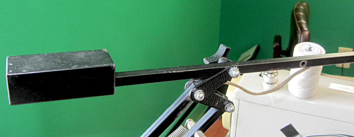
Moving the pivot point of the rebuilt desk lamp arm back about 75 mm put it at the proper spot:
Rebalanced desk lamp boom
That required snaking new wiring from the transformer in the base through the upright and out through the boom to the LED floodlamp. I used a random length of speaker cable from the Big Box o’ Heavy Wires, although it doesn’t take much to carry 300 mA at 12 V.
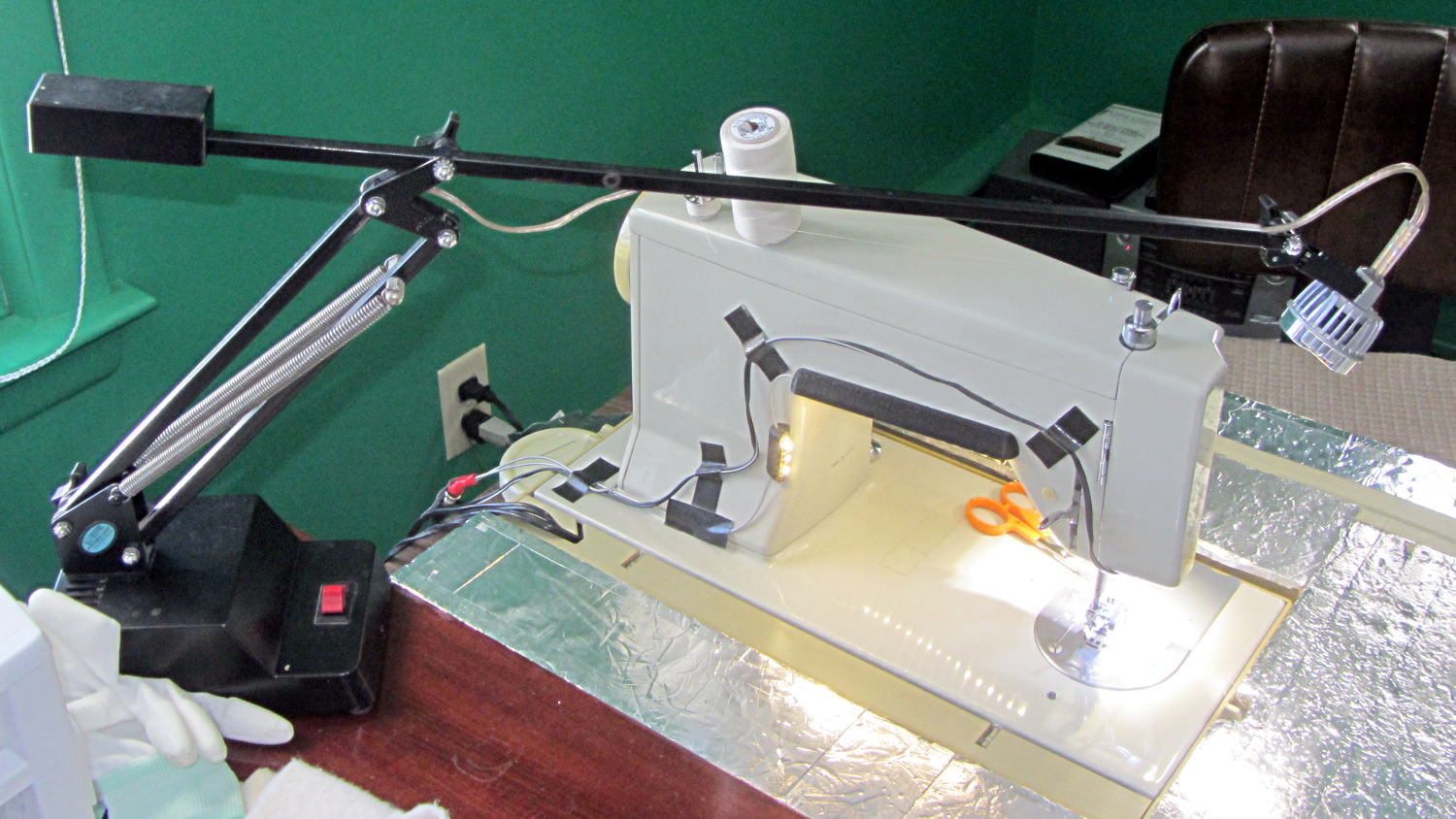
The lamp head now reaches the work area and the base stays out of the way:
Rebuild desk lamp over sewing machine
It is, we both agree, hideously ugly, but it puts plenty of light at the right spot.
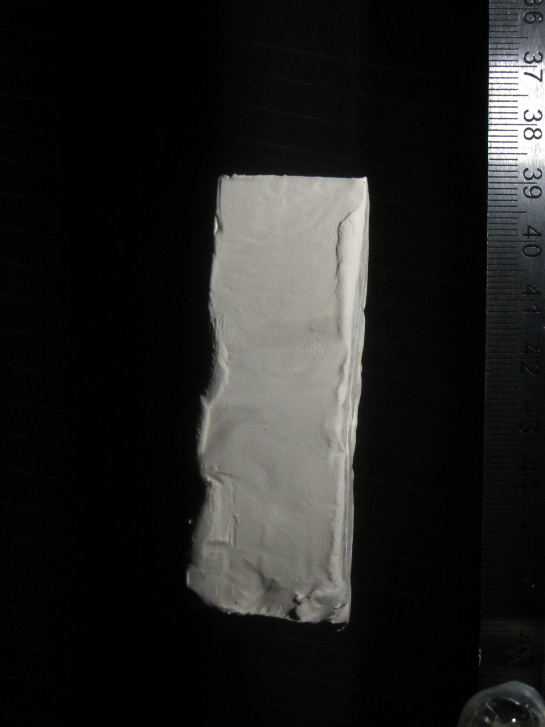
A black background does wonders to improve the presentation:
Clay slab – 180 ms
That’s ISO 800, 1/10 s, f/8, 30 cm manual focus, with the flash about 20 cm away in the right foreground. The Xenon flash has a 1 µF capacitor giving a pulse width of about 100 µs. The LED visible on the lower right flashed 1 ms after the lump broke the laser beam.
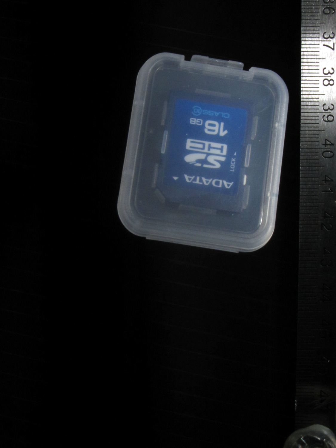
Rather than do science, I shoveled small objects through the aperture…
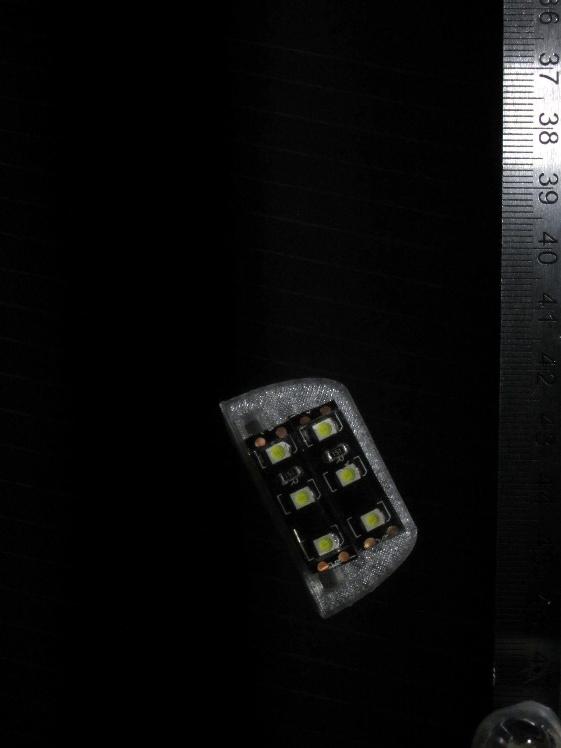
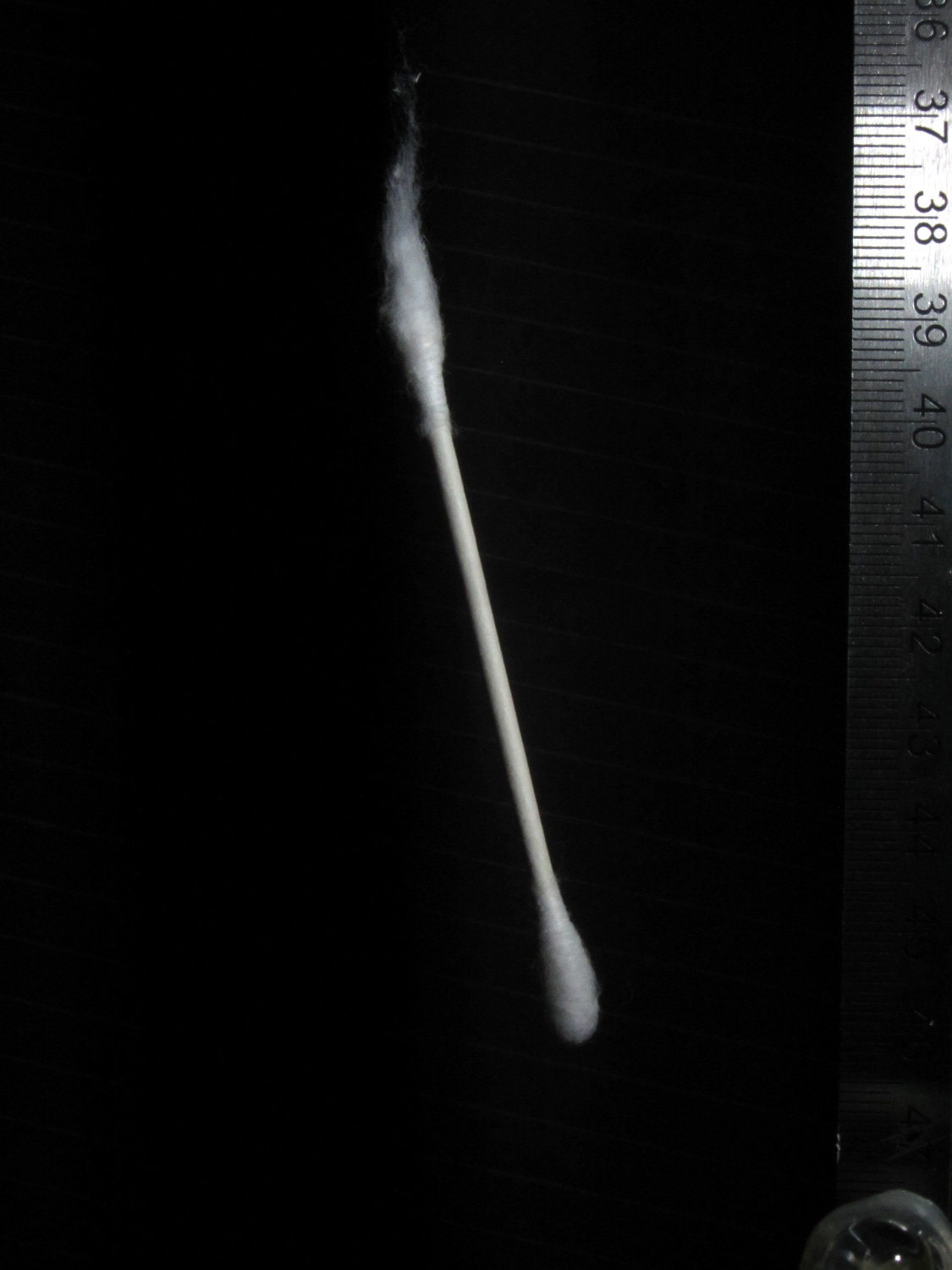
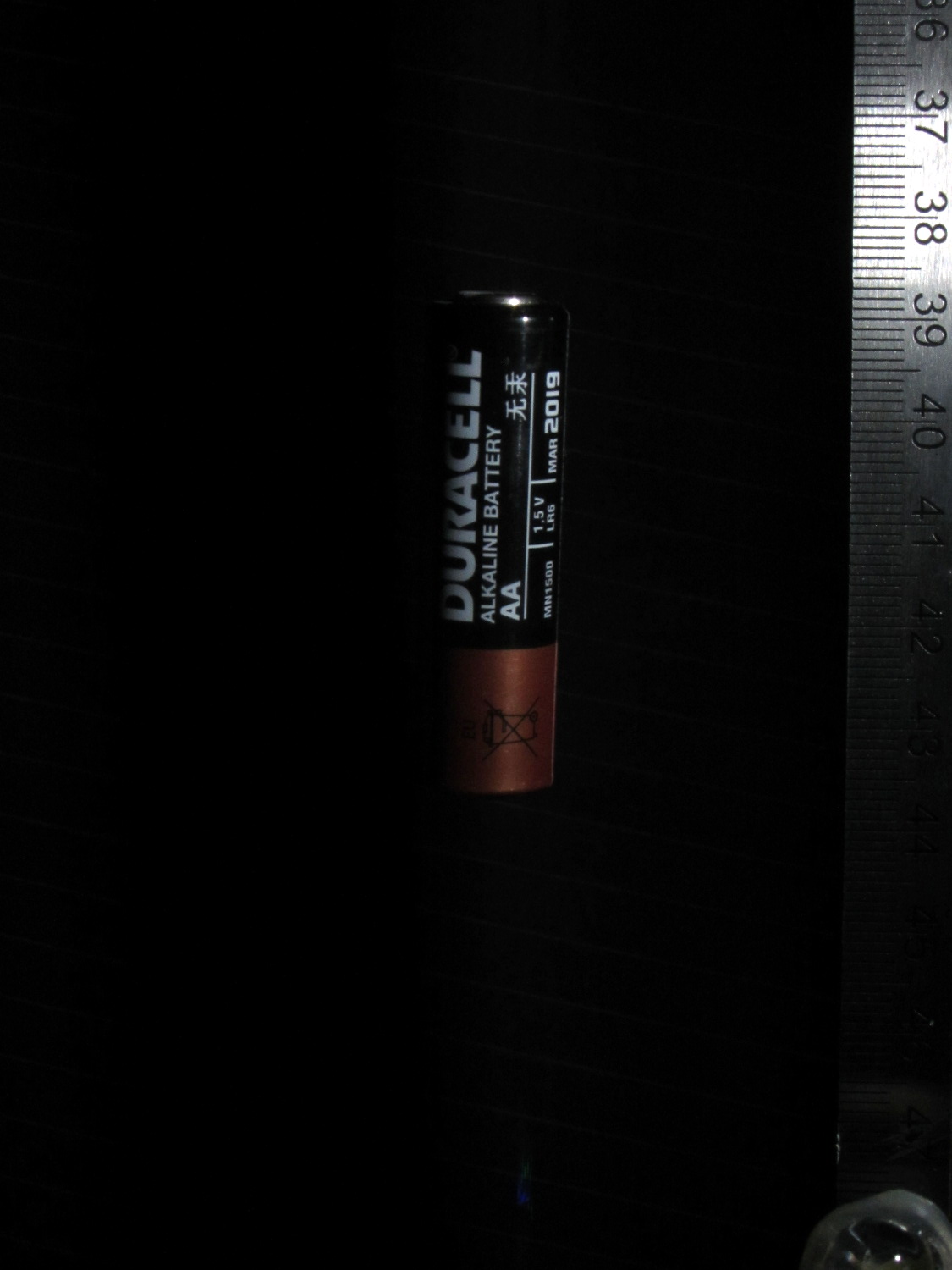
Falling LED striplightFalling Sierpinski gasketFalling clay blockFalling cotton swabFalling AA cellFalling SDHC CardFalling lock washer
Tweaking the Arduino program to fire the LED 10 ms after the beam breaks, then fire the Xenon strobe 180 ms later produces this result:
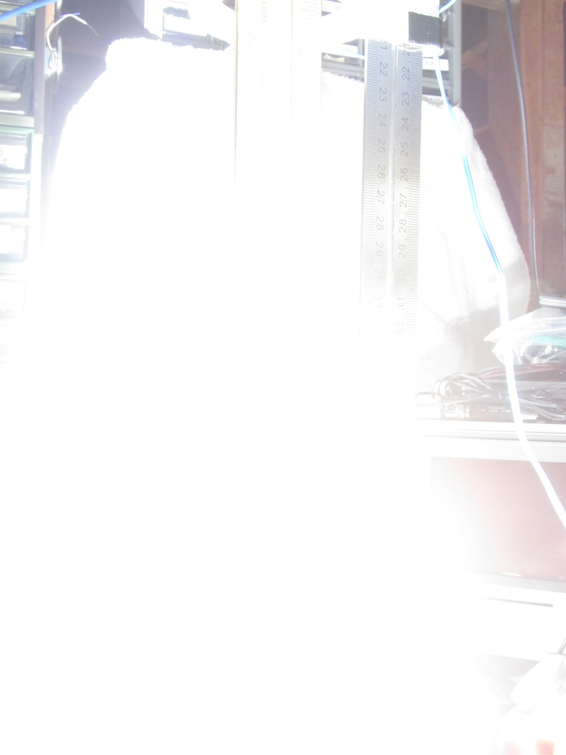
Drop test – ISO 800 – 100 ms f8 – overexposure
Obviously, that’s far too much light: ISO 800, 1/10 sec, f/8, with the flash a few inches from the action. There aren’t many free variables:
Shutter must be open long enough to span the timing jitter
Aperture is already as small as it gets for good depth of focus
ISO speed may be too high
Flash intensity is fixed for a given capacitor
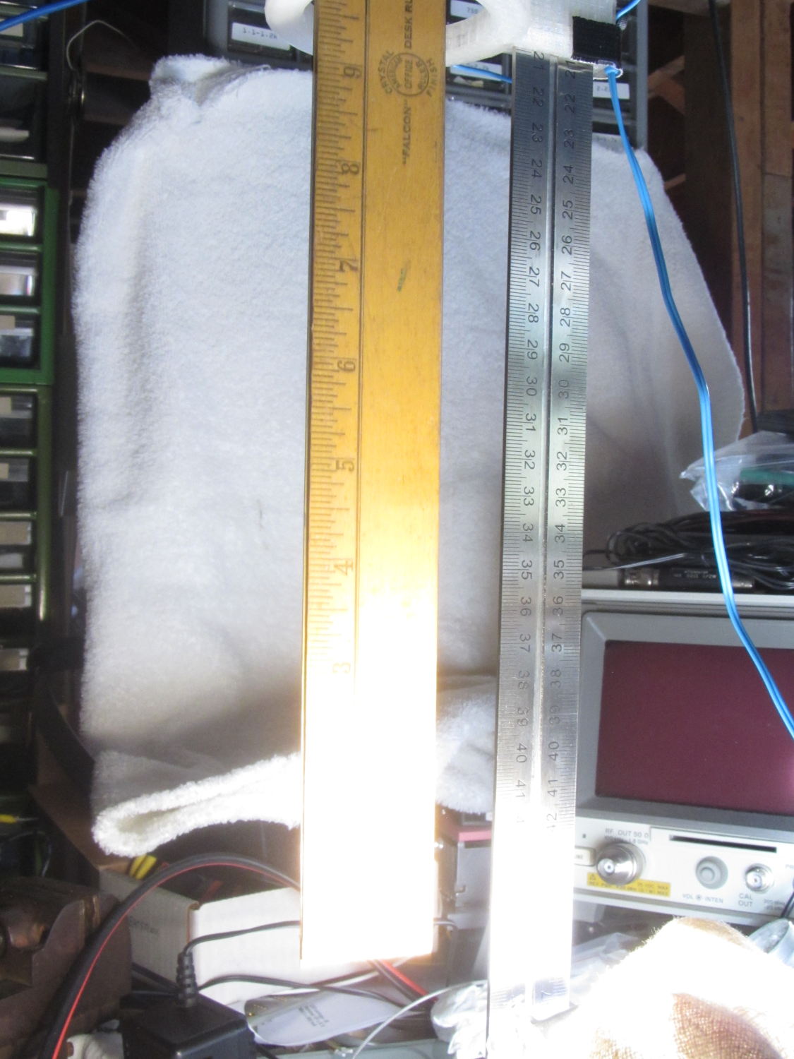
Throwing a shop rag over the flash helps a bit, capturing the ruler suspended in mid-air:
Drop test – ISO 800 – 100 ms f8 – cloth
However, replacing the 250 µF electrolytic flash capacitor with a 1 µF film cap reduces the stored energy by roughly an order of magnitude and reduces the flash pulse duration to about 100 µs.
The bottom two inches of the ruler now have lighting from the flash, while the rest of the image looks pretty good in natural light:
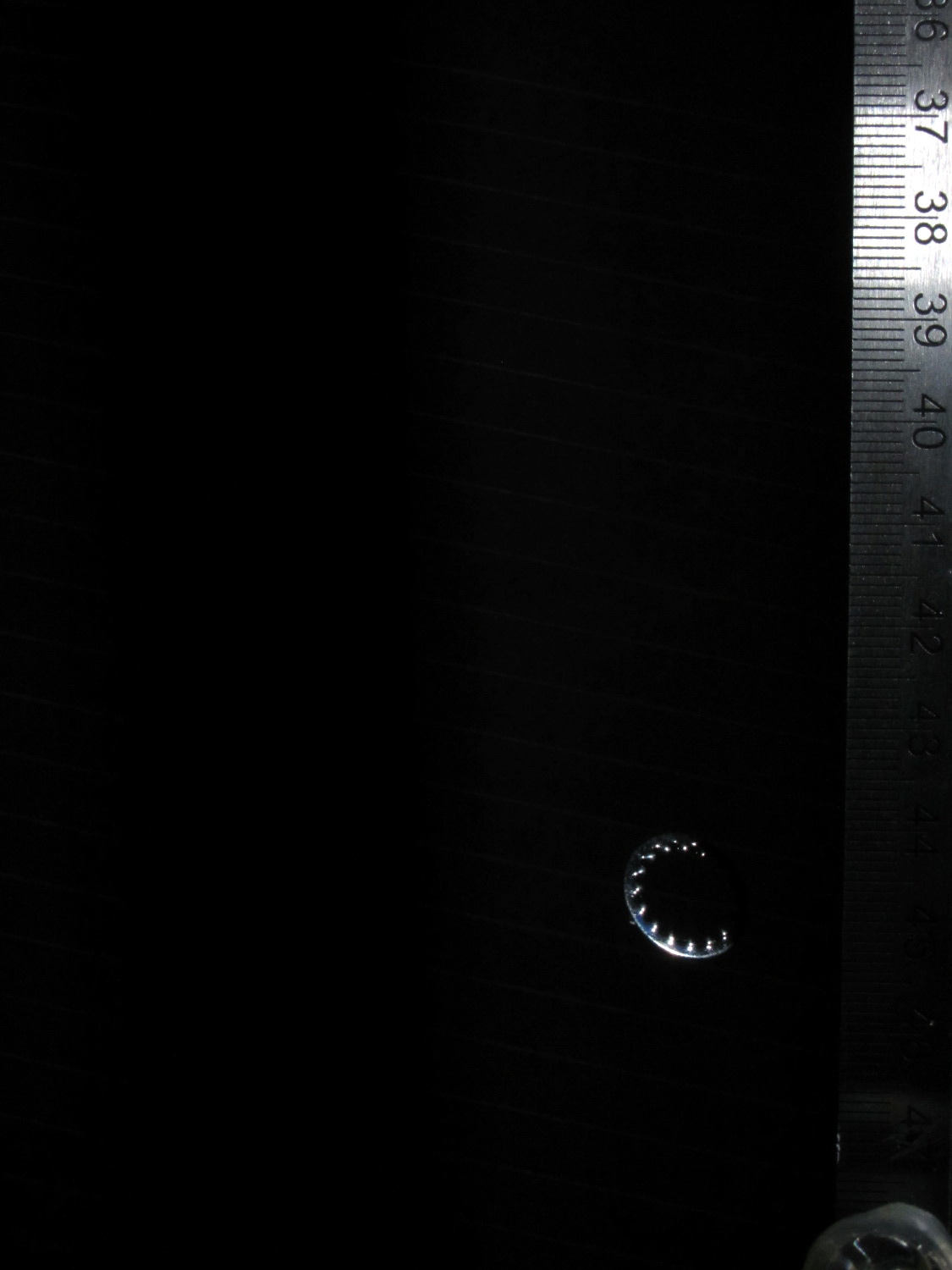
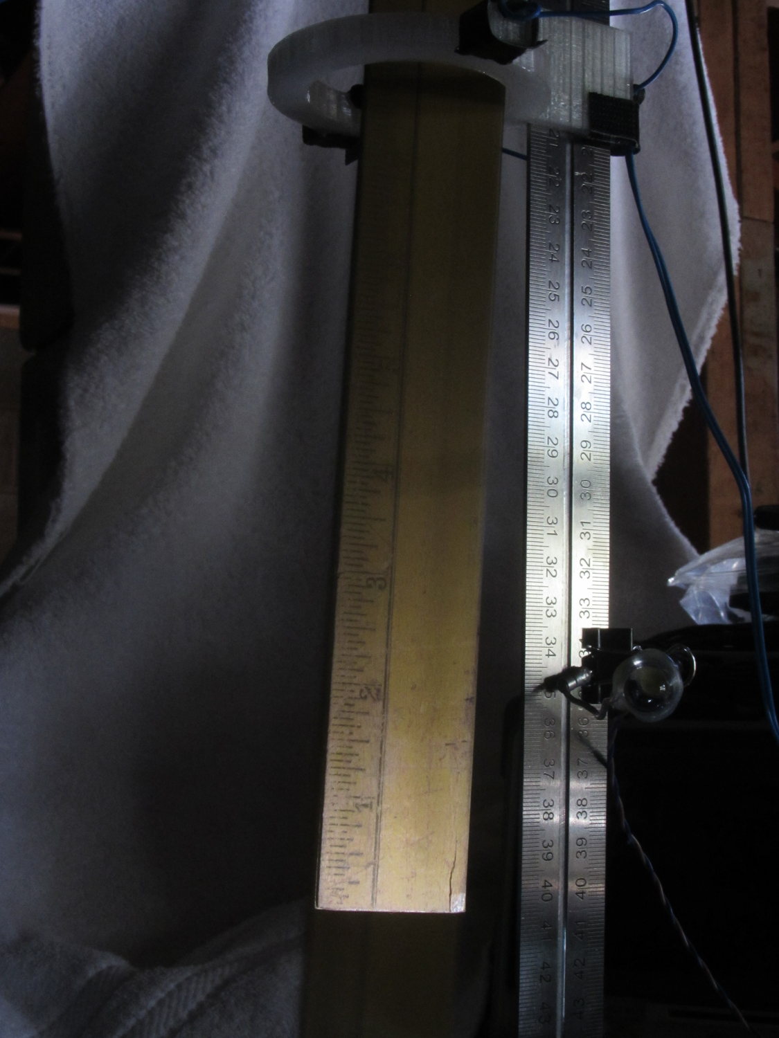
Drop test – ISO 800 – 100 ms f8 – 1 uF
It turns out that having the laser and photodiode beam-break sensor within the view (the white ring at the top) doesn’t work, as the CHDK motion detector will notice the red spot on the ruler and trigger the shutter before the LED (clipped to the right of the vertical steel scale) flashes.
Several more trials showed that the flash fires consistently, but (as expected) the shutter triggering has some jitter. In this case, the shutter remained open after the flash and captured a blurred image as the ruler continued to fall:
Drop test – ISO 800 – 100 ms f8 – tail
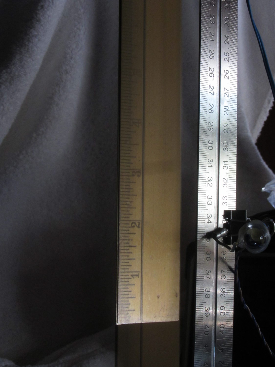
Here, the shutter closed immediately after the flash, eliminating the blurred tail:
Drop test – ISO 800 – 100 ms f8 – no tail
Having the shutter close before the object reaches the bottom of the image is a Bad Thing, as it means the shutter triggered too early.
In both cases, the sharp image of the ruler overlays the blurred image captured in natural light. That’s more visible toward the top of the picture where the flash doesn’t reach very well.
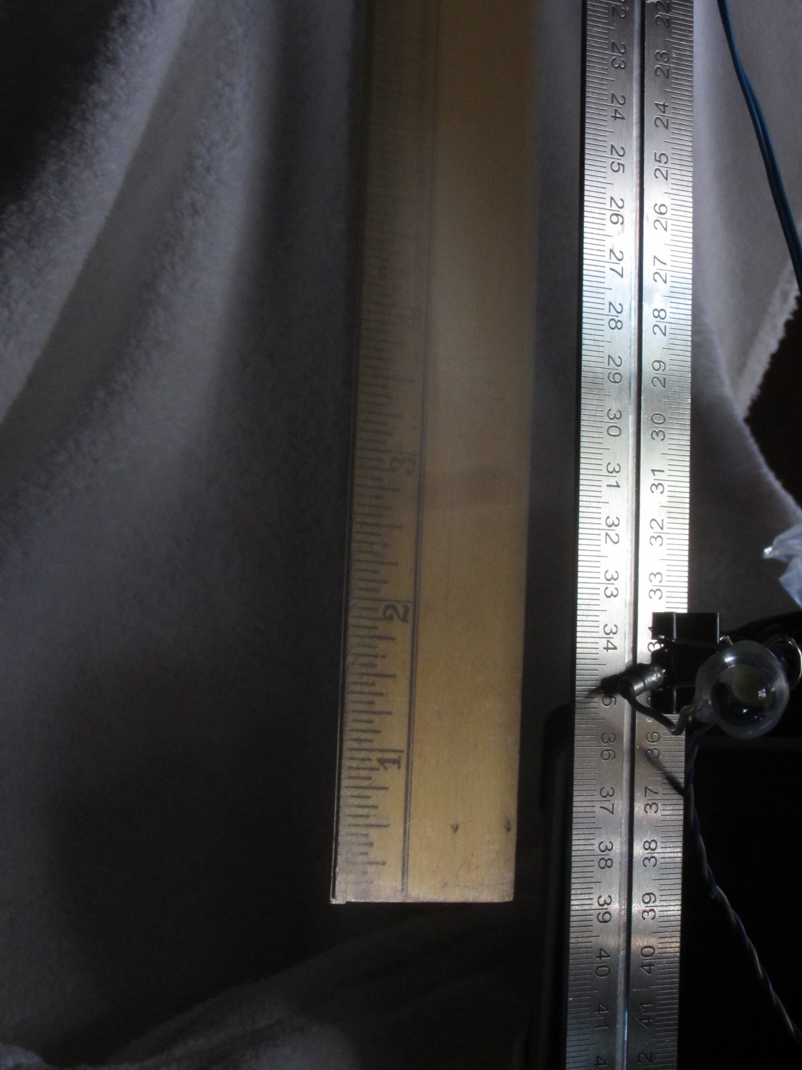
I aligned the laser beam-break detector at 200 mm on the scale and the flash fired when the tip of the ruler was at 390 mm = 190 mm below the beam. The LED blinked 10 ms after the beam break and the Xenon flash fired at 180 ms; given all the vagaries involved, 190 mm is just about spot on the (revised) estimates.