Ed Nisley's Blog: Shop notes, electronics, firmware, machinery, 3D printing, laser cuttery, and curiosities. Contents: 100% human thinking, 0% AI slop.
Tag: Improvements
Making the world a better place, one piece at a time
At some point I got two strap wrenches with rubber straps. No reinforcements, just pure rubber or neoprene or whatever. I’d cinch up on something, apply some torque, and the straps would stretch beyond belief. I’d always wanted to replace the straps and, finally, when I had the shop replace the van’s belts, I asked for a timing(*) belt from their scrap can.
The smaller wrench required slitting the belt lengthwise and discarding two ribs. A pop rivet attaches two small chunks of the belt to form a block; the original belt had a molded-in triangular end:
Strap Wrench timing belt refit – small
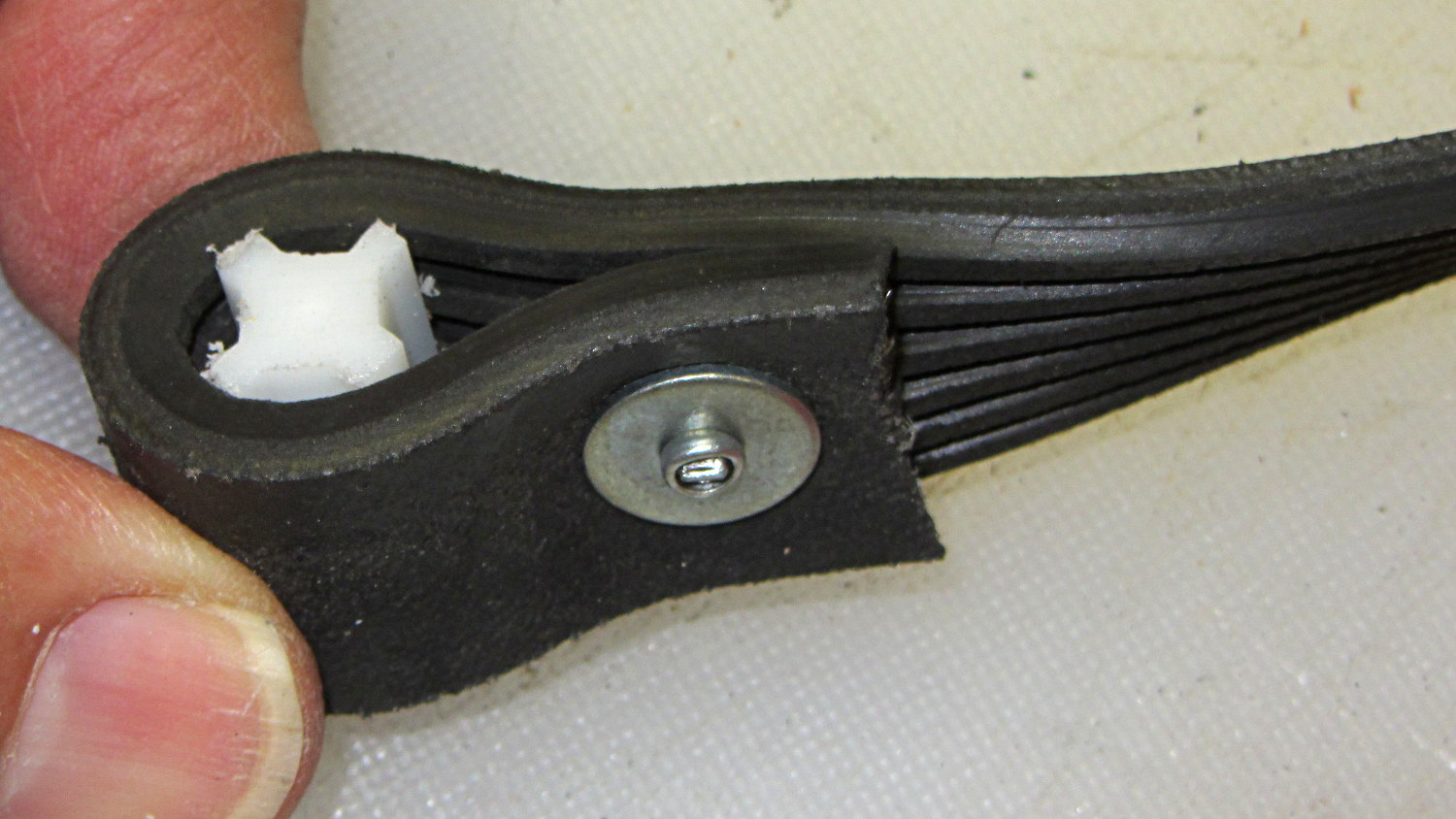
The larger belt required a plastic filler, cut from something that might once have been a flag holder, riveted into a loop that firmly jams inside the wrench handle:
Strap Wrench timing belt refit – large
Nothing fancy, but strap wrenches work much better when the straps don’t stretch!
Found these pix while I was looking for something else…
(*) As Dan points out in the comments, this is a serpentine belt. I got it while the shop replaced the Sienna’s timing belt; that’s my story and I’m sticking with it…
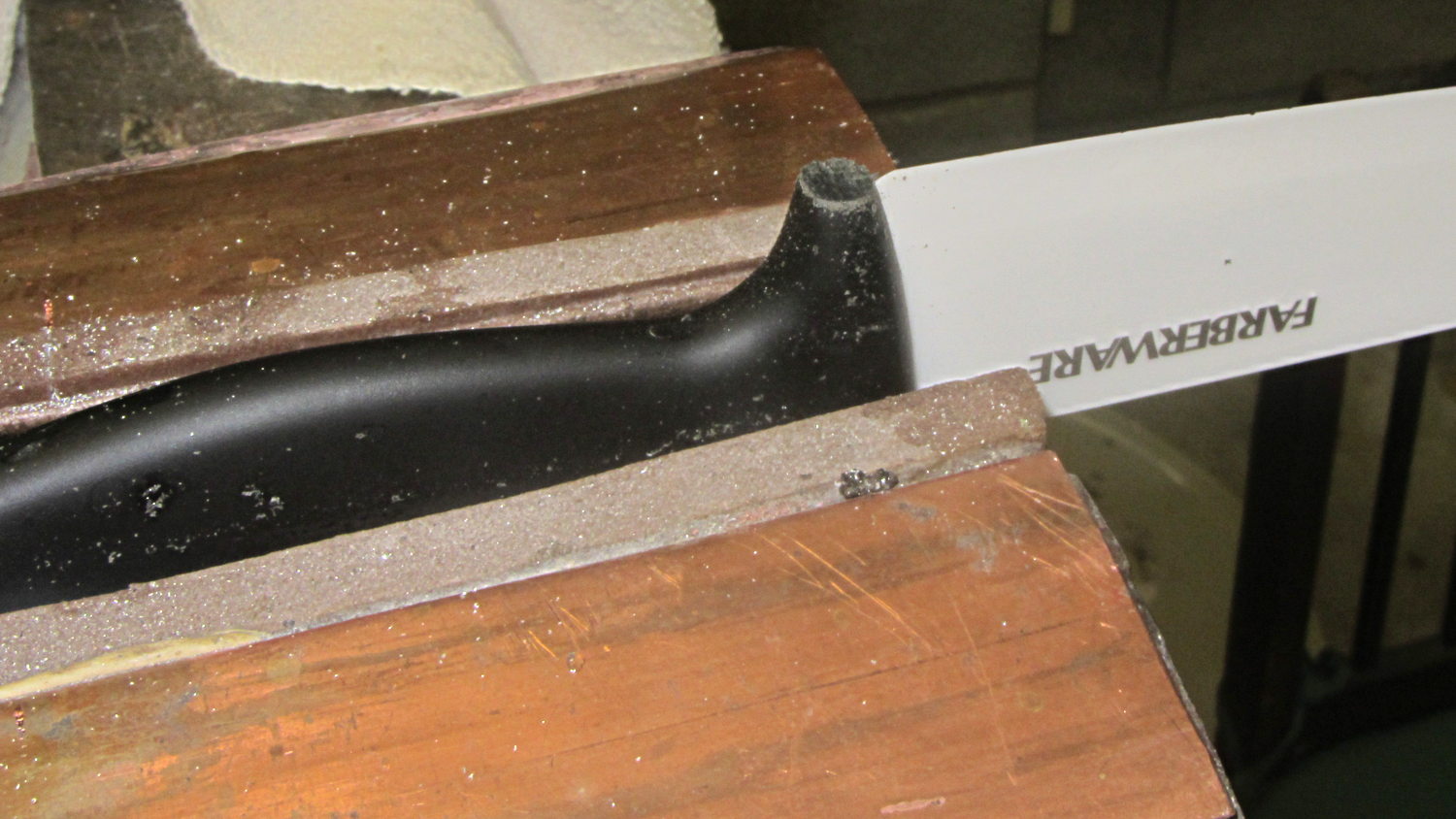
For whatever reason, the handle of the ceramic knife extended a few millimeters below the blade heel:
Farberware ceramic knife
Now it doesn’t:
Farberware ceramic knife – trimmed handle
Which makes it much more usable for the kind of chopping I do around here: the blade hits the cutting board squarely, producing chunks of veggies along its entire length.
A coarse file removed most of the stub, followed with a fine file and a little sandpaper action to round the edges.
Amazingly enough, none of that fussing around touched the blade, nor did I gash myself!
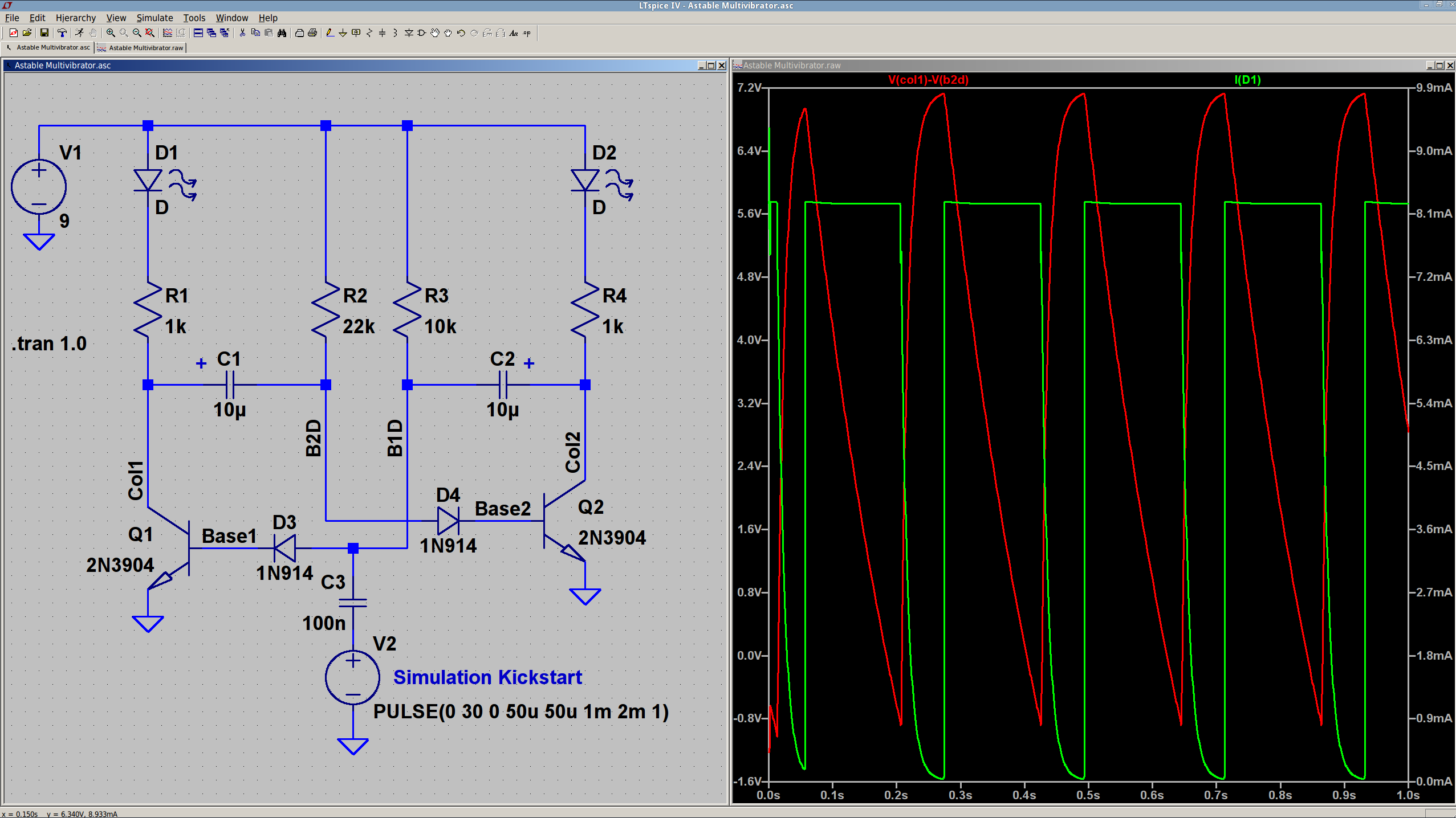
The 10 µF caps scale the output to visible blinkiness. Their polarity may seem backwards, but the red trace in the simulation shows that the net voltage is positive in that direction for nearly the entire cycle. They see only two forward biased junctions in the other direction, so they shouldn’t blow up.
I built it with resistors from the SqWr junk box parts cabinet that were close to the nominal values.
Connecting the transistor base / cap charging resistors to the power supply, rather than the LEDs, gets rid of the tiny current when the LEDs should be off.
The cap-and-pulse-generator dingus on the bottom kickstarts the simulation; it doesn’t have any physical significance.
Memo to Self: Build one with a pair of ET227 transistors and some 100 W tungsten bulbs…
Commercial LED strip lights for sewing machines mount their cables with little stick-on anchors and cable ties. I wasn’t happy with the cable tie thing and finally figured this out:
Kenmore 158 – LED strip light cable clips
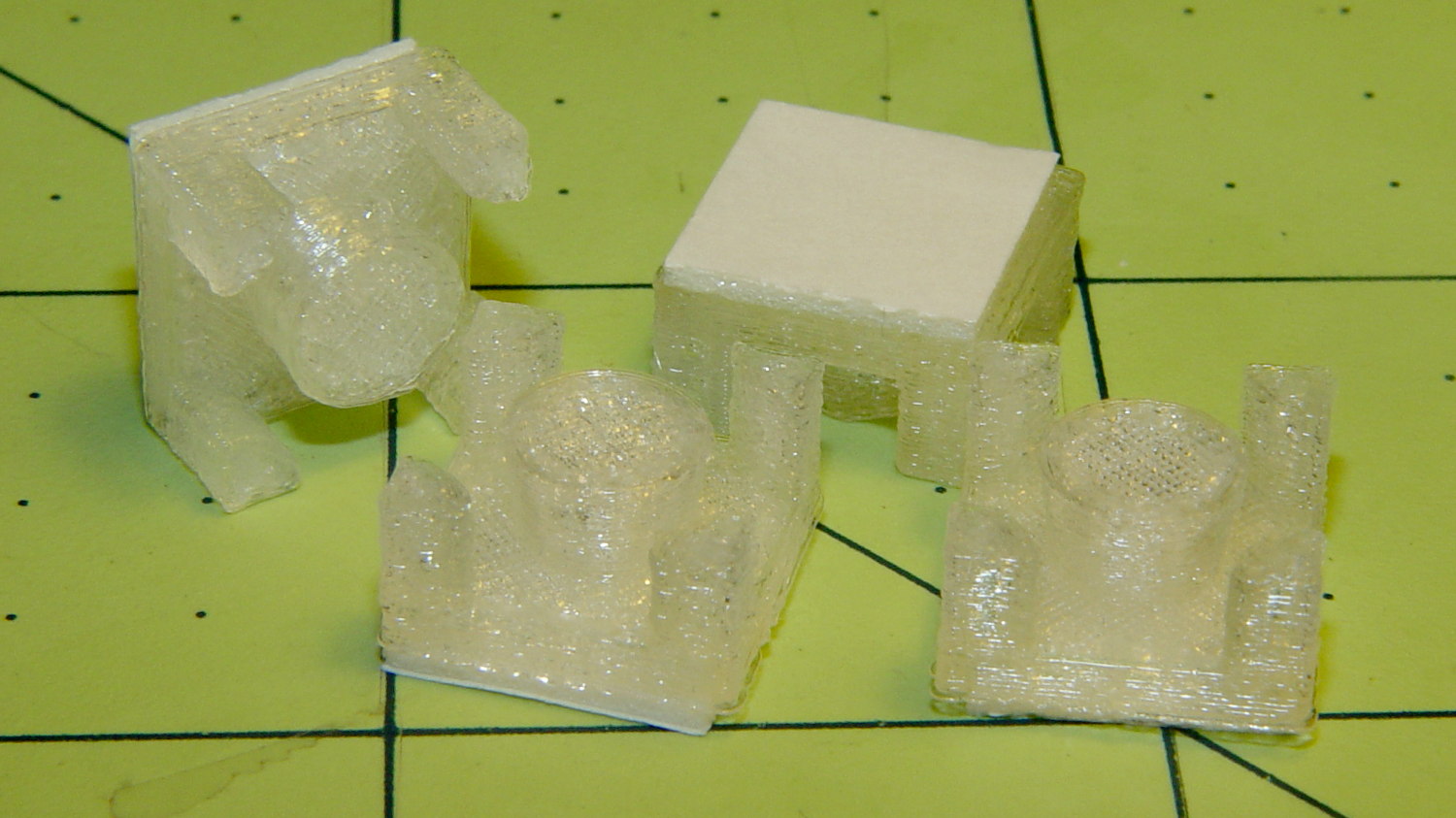
The clips have that size & shape because they fit exactly atop some pre-cut foam squares from the Tape Lookaside Buffer:
LED strip light cable clips
You can see the shape better in the solid model:
LED Cable Clips
The central bollard has a slight taper to retain the cable, the quarter-posts are straight, and they’re both twice the cable diameter tall. The clearance between the center and corner posts at the top matches the cable diameter, so there’s a bit of bending room at the bottom, and, with the cable bent around the center, it won’t fall out on its own.
The cute coaxial cable I’m misusing for the LED strips measures just shy of 2 mm, making these into little bitty things. The corner posts seem surprisingly strong, despite 3D printing’s reputation for crappy quality; I haven’t been able to break one off with more effort than seemed warranted.
The OpenSCAD source code:
// LED Cable Clips
// Ed Nisley - KE4ZNU - October 2014

//- Extrusion parameters must match reality!

ThreadThick = 0.20;
ThreadWidth = 0.40;

HoleWindage = 0.2;			// extra clearance

Protrusion = 0.1;			// make holes end cleanly

AlignPinOD = 1.70;			// assembly alignment pins: filament dia

function IntegerMultiple(Size,Unit) = Unit * ceil(Size / Unit);

//----------------------
// Dimensions

Base = [12.0,12.0,IntegerMultiple(2.0,ThreadThick)];	// base over sticky square

CableOD = 2.0;

BendRadius = 3.0;

Bollard = [BendRadius,(sqrt(2)*Base[0]/2 - CableOD - BendRadius),2*CableOD];
B_BOT = 0;
B_TOP = 1;
B_LEN = 2;

NumSides = 5*4;

//----------------------
// Useful routines

module PolyCyl(Dia,Height,ForceSides=0) {			// based on nophead's polyholes

  Sides = (ForceSides != 0) ? ForceSides : (ceil(Dia) + 2);

  FixDia = Dia / cos(180/Sides);

  cylinder(r=(FixDia + HoleWindage)/2,
           h=Height,
           $fn=Sides);
}

module ShowPegGrid(Space = 10.0,Size = 1.0) {

  RangeX = floor(100 / Space);
  RangeY = floor(125 / Space);

	for (x=[-RangeX:RangeX])
	  for (y=[-RangeY:RangeY])
		translate([x*Space,y*Space,Size/2])
		  %cube(Size,center=true);

}

//----------------------
// Build it

ShowPegGrid();

intersection() {
	translate([0,0,(Base[2] + Bollard[2])/2])			// overall XYZ outline
		cube(Base + [0,0,Bollard[2]],center=true);

	union() {
		translate([0,0,Base[2]/2])						// oversize mount base
			scale([2,2,1])
				cube(Base,center=true);

		for (i=[-1,1] , j=[-1,1]) {						// corner bollards
			translate([i*Base[0]/2,j*Base[1]/2,(Base[2] - Protrusion)])
				rotate(180/NumSides)
				cylinder(r=Bollard[B_BOT],h=(Bollard[B_LEN] + Protrusion),center=false,$fn=NumSides);

		translate([0,0,(Base[2] - Protrusion)])			// center tapered bollard
			cylinder(r1=Bollard[B_BOT],r2=Bollard[B_TOP],h=(Bollard[B_LEN] + Protrusion),center=false,$fn=NumSides);
		}
	}
}
Now that I think of it, maybe a round clip would look nicer. The central bollard would stay, but the circular outside rim could have three cutouts. When these fall off, I’ll give that a try.
They may be square and clunky, but they look much better than Gorilla Tape…
The sewing machine motor runs from 120 V AC or DC, drawing a few amps with the rotor locked, so a hulking 300 V 10 A bridge rectifier (Motorola MDA962-4, if you’re keeping score) seems grossly overrated. On the other paw, I have one, so why not?
The mounting holes pass 6-32 machine screws, but the recesses in the top seem meant for fillister head screws that I don’t have. Fortunately, I do have a lathe:
MDA962-4 rectifier – screw head adjustment
And then they just drop into place:
MDA962-4 Bridge Rectifier – installed
You can see why recessing the screw head below the top of the rectifier is a Good Thing.
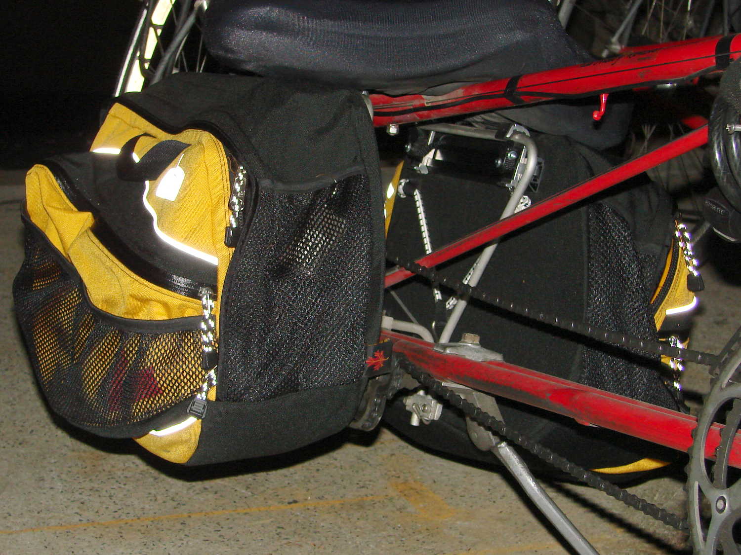
The retina-burn white reflective tag under the black hand strap is actually a foreshortened view of the Arkel logo.
They’re longer and taller than the old packs, which isn’t entirely a Good Thing: the inside bag gently kisses the pavement during steeply banked high speed turns. The main compartment is slightly narrower, so I bent the license plates (which used to fit neatly on the bottom) to form a hard floor with a low lip on the inside edge. That, in combination with tightening the pack’s internal strap, prevents the foam-core bottom panel from drooping; maybe the edge won’t hit the pavement quite so often.
They also ride much higher on the racks. To install the packs, I had to unbolt the seat to raise it upward, slide the packs underneath, twiddle the clamps onto the rack rods, then reinstall the seat. Those puppies are not getting loose without tools and a struggle!
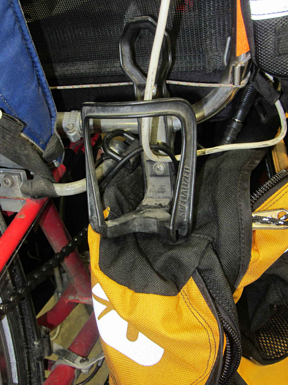
I’m not entirely happy with that arrangement, as the holder sits snug against the rear packs. So far, I rarely need those in addition to the RT-40s, as each underseat bag can swallow an upright gallon milk jug or two Butternut squashes in addition to all the other stuff I normally carry.
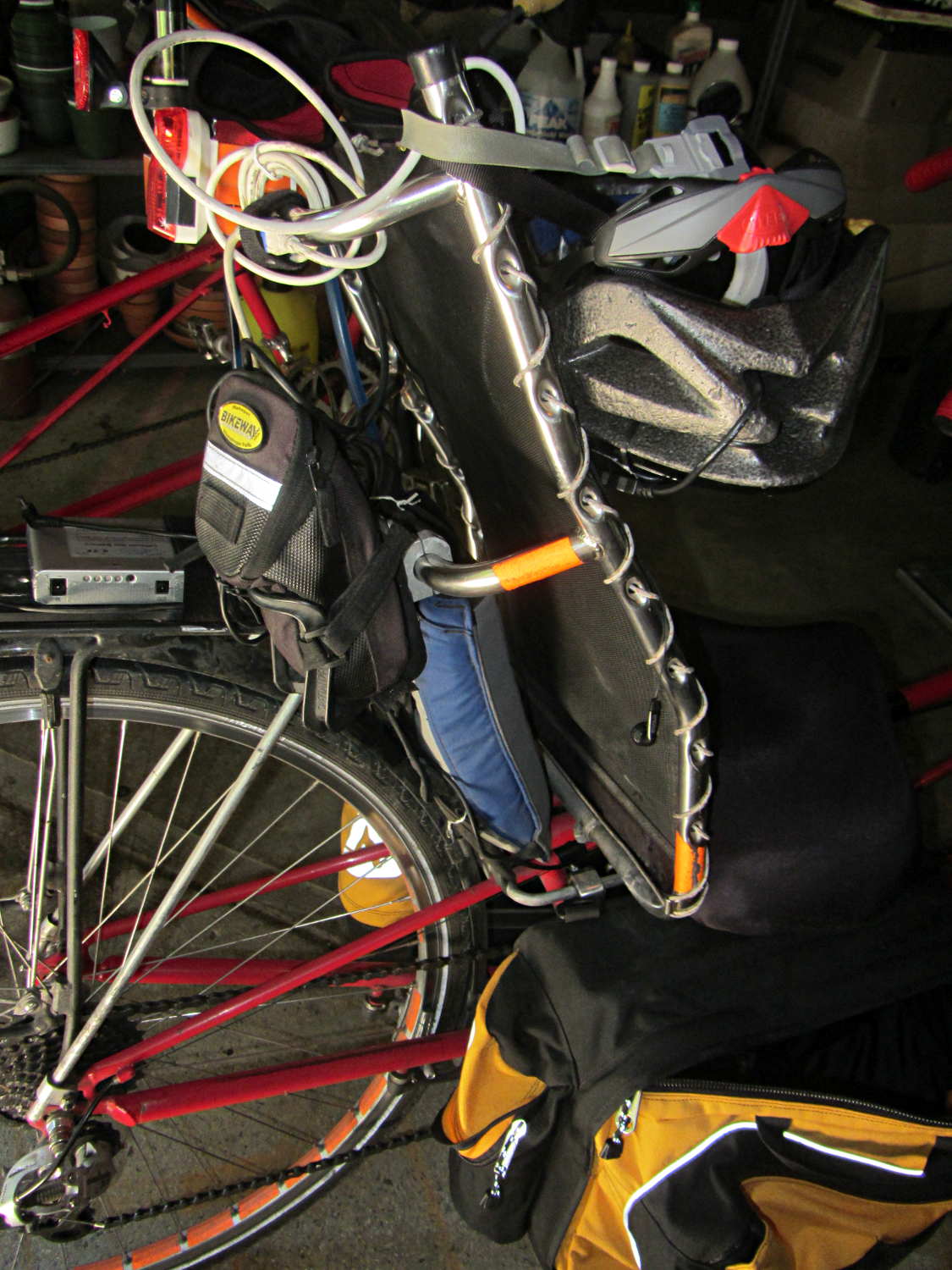
The array of reflective patches and piping and pull tabs probably makes me look (more) like a low-flying UFO at night, but that’s fine with me: the more it resembles a UFO, the less hassle I get.
Steelcase lists the arm rests on their Leap chairs as “factory installed” and not removable, perhaps because the brackets supporting the arms also support the backrest. In the event you must ever remove the arms, perhaps because your wife decides she’d like to try the chair without them, it’s straightforward.
Loosen the Torx screw visible through the slot in the bottom of the plastic shroud about a dozen turns (it will not click or feel loose), use a flat screwdriver to unlock the shroud from the flat plastic plate on the seat side of the bracket, then forcibly pull the sides of the shroud outward until you can pull the arm extension mechanism up-and-out of these slots in the bracket:
Steelcase Leap – arm bracket
This view from the side of the chair shows the screw hole in the bottom, with a pair of holes for alignment pins beside it:
Steelcase Leap – arm bracket
You can remove the flat plate by pushing the latch at the top center (just below the backrest screw boss), then sliding the plate upward.
As nearly as I can tell, there’s no way to remove the shroud from around the arm extension mechanism, so you must pull off the whole thing in one lump:
Steelcase Leap – arm mechanism
The two pairs of slots in the edges of the shroud engage tabs on the plastic plate; that’s why you need the flat screwdriver.
The two pins on the bottom lock the arm into the bracket: you must raise it vertically until those come out, after which you can ease the bottom outward until the pins on the sides (which you can’t see inside the shroud) disengage from the bracket slots.
It takes a whole lot more force than seems necessary, but it can be done.
Wrap Gorilla tape around the raw edges until you decide whether it’s worthwhile to design and print a pair of plastic caps to cover the whole bracket.