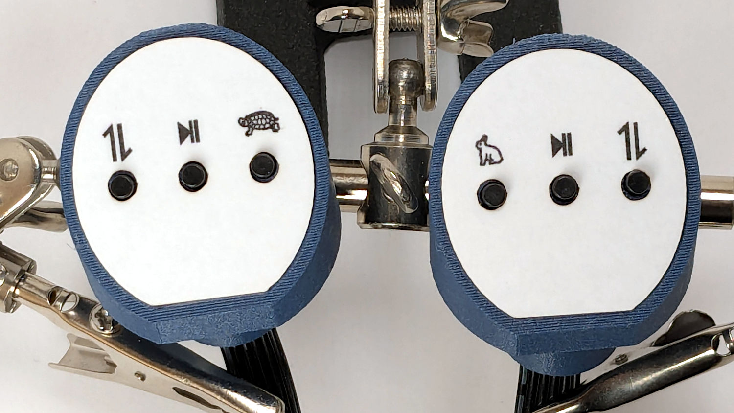
Each of the HQ Sixteen’s handlebars has a cap with control buttons:
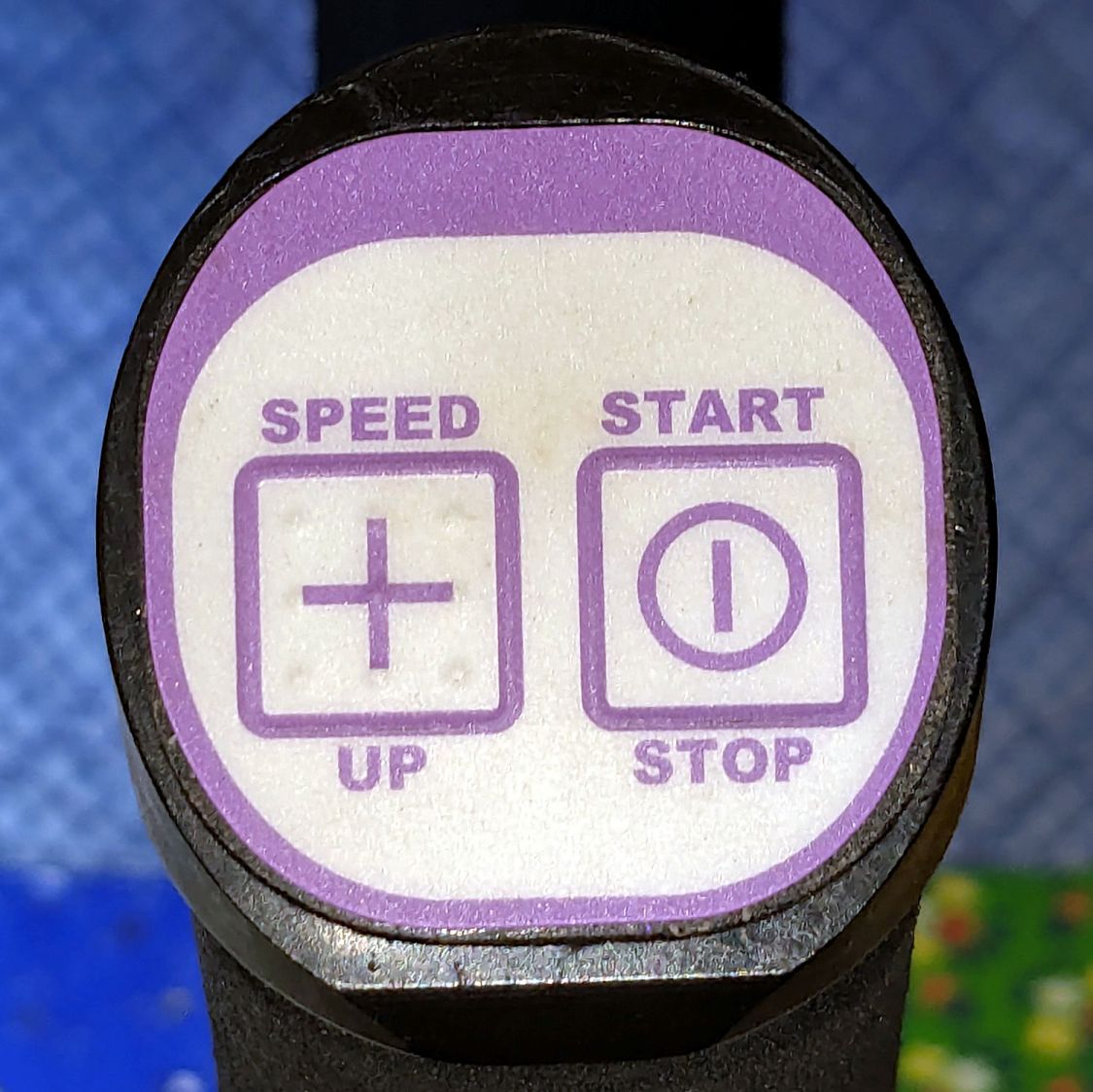
The left cap:
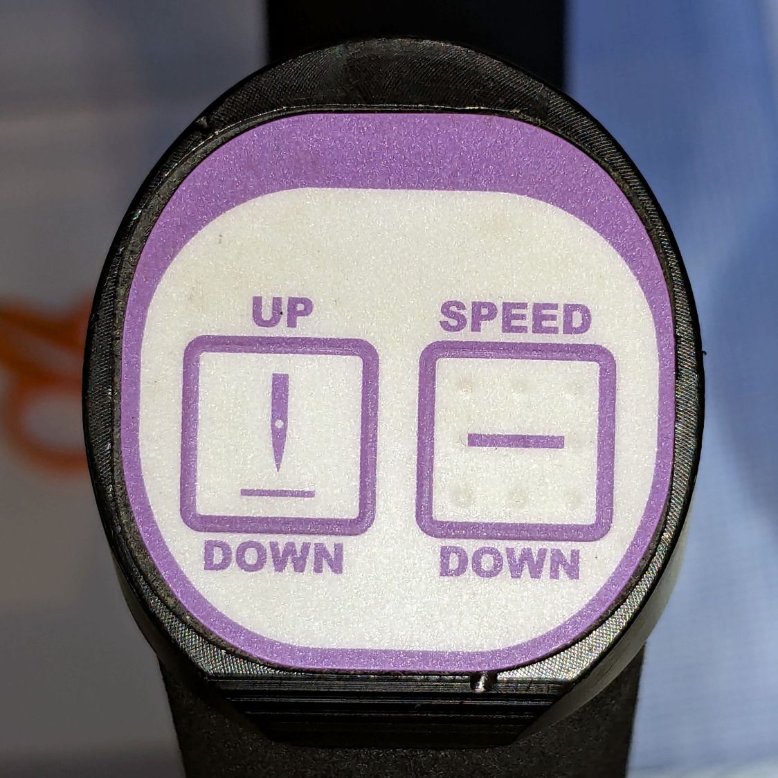
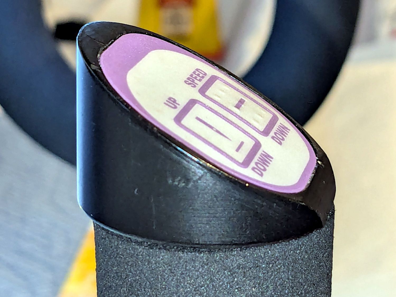
The right cap:
The membrane switch overlay has textured bumps, although both of us have trouble finding them.
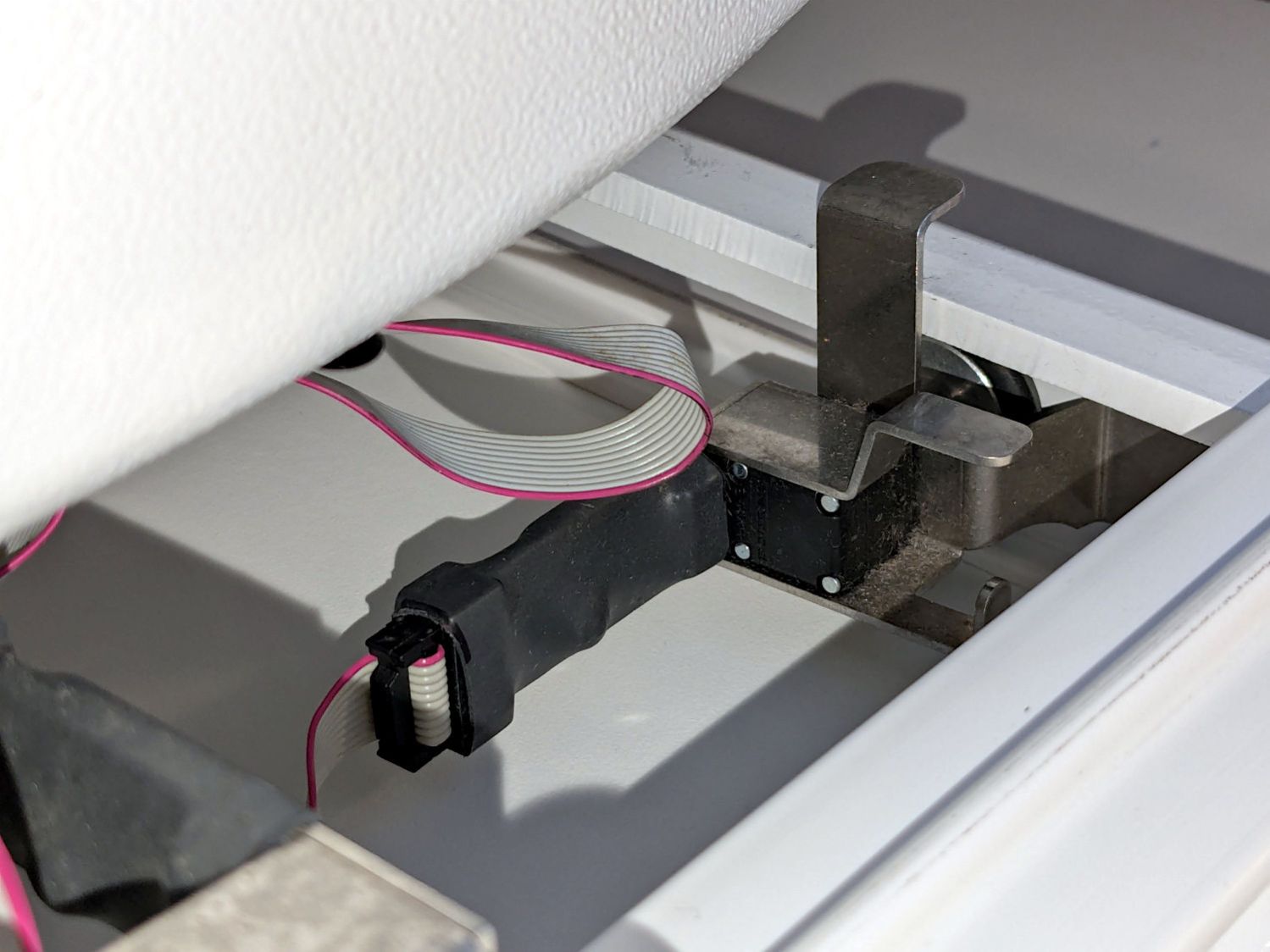
The Start / Stop switch gets the most use and, as you’d expect, has become intermittent after two decades of use.
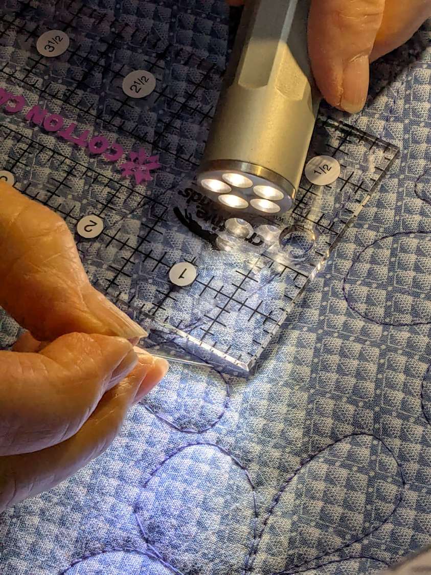
Mary thinks a Start / Stop switch on both caps would be an improvement, letting her position quilting rulers with her right hand and run the machine with her left hand & thumb. I don’t know how the switches are wired, but the wiring suggests either simple single-bit inputs or a small matrix.
She also finds membrane switches difficult to press, so I’m in the process of replacing the control caps with something more to her liking.
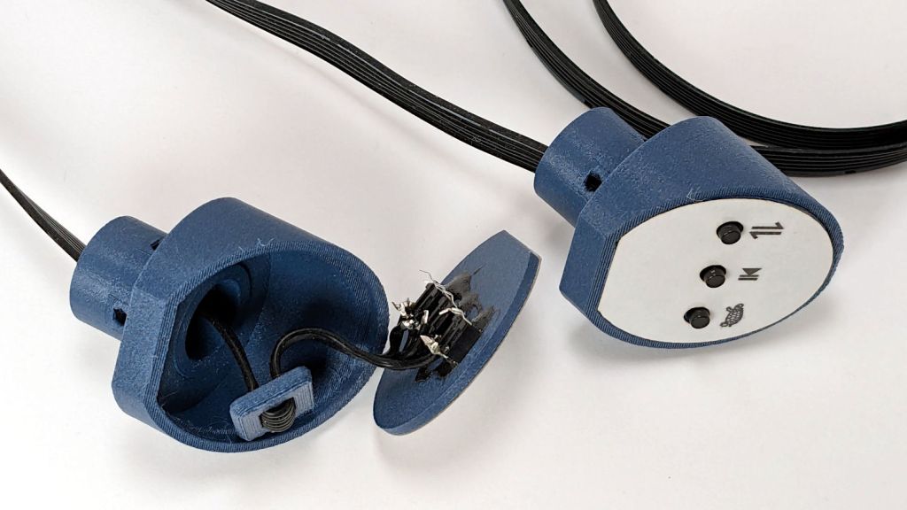
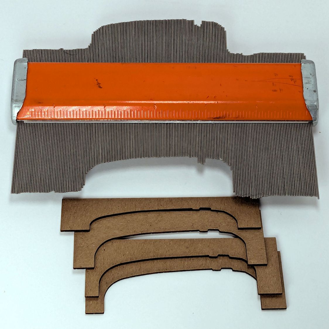
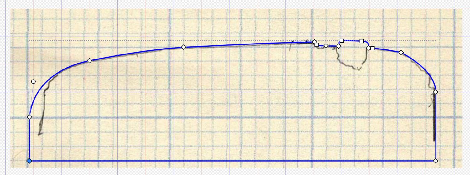
The current concept goes a little something like this:
Stipulated: my art hand is weak.
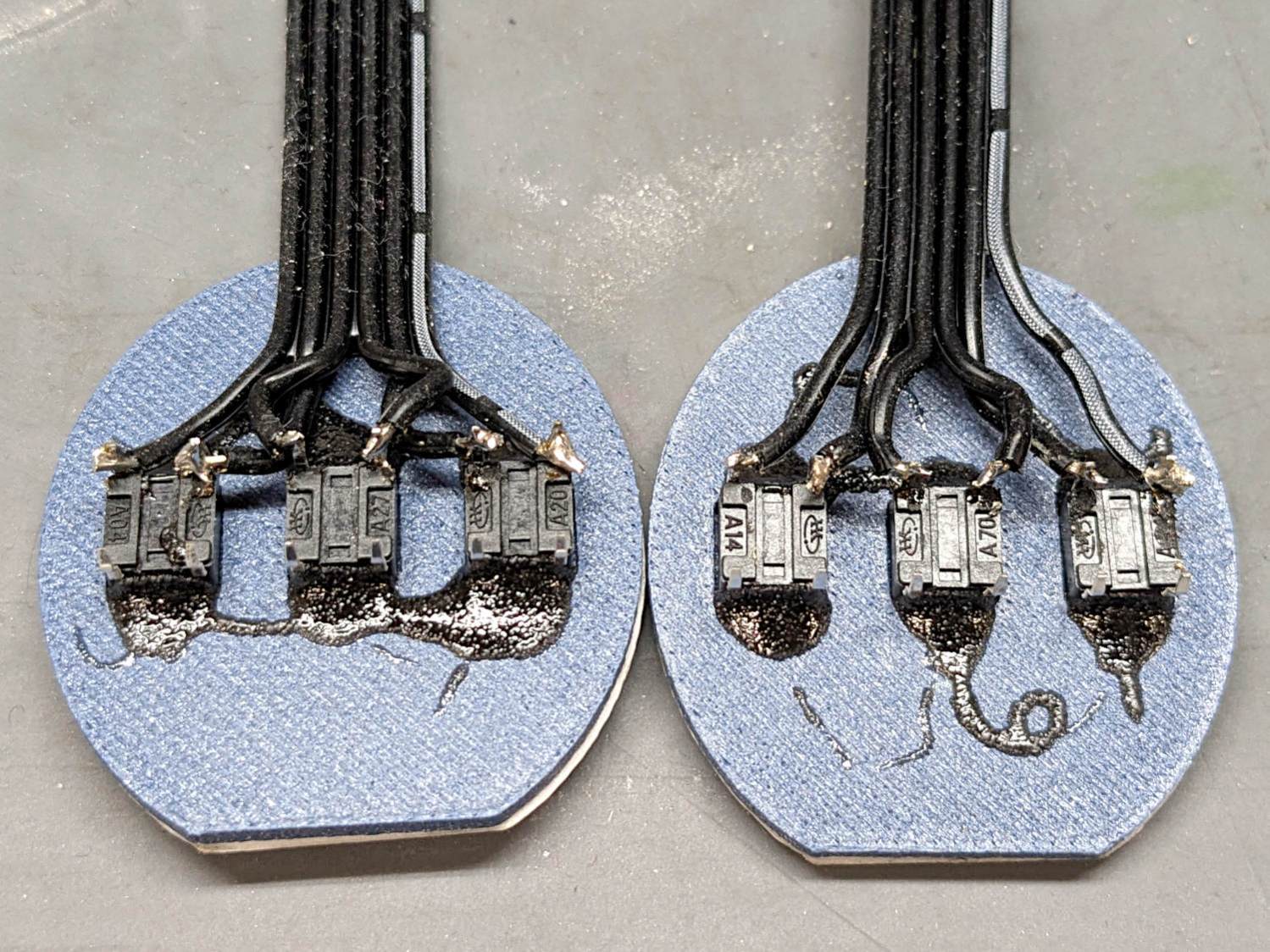
Those are little bitty SMD switches:

They’re easy to locate by touch, with a stem length chosen to “feel right” when pushed.
They have been grievously misapplied:
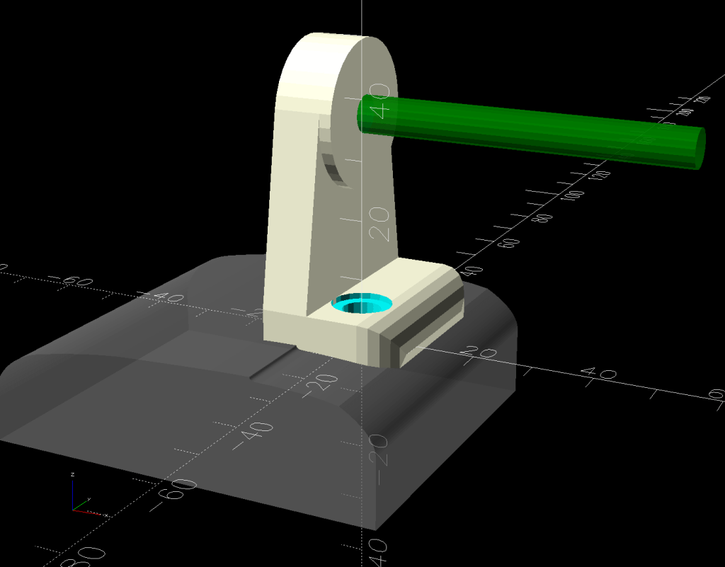
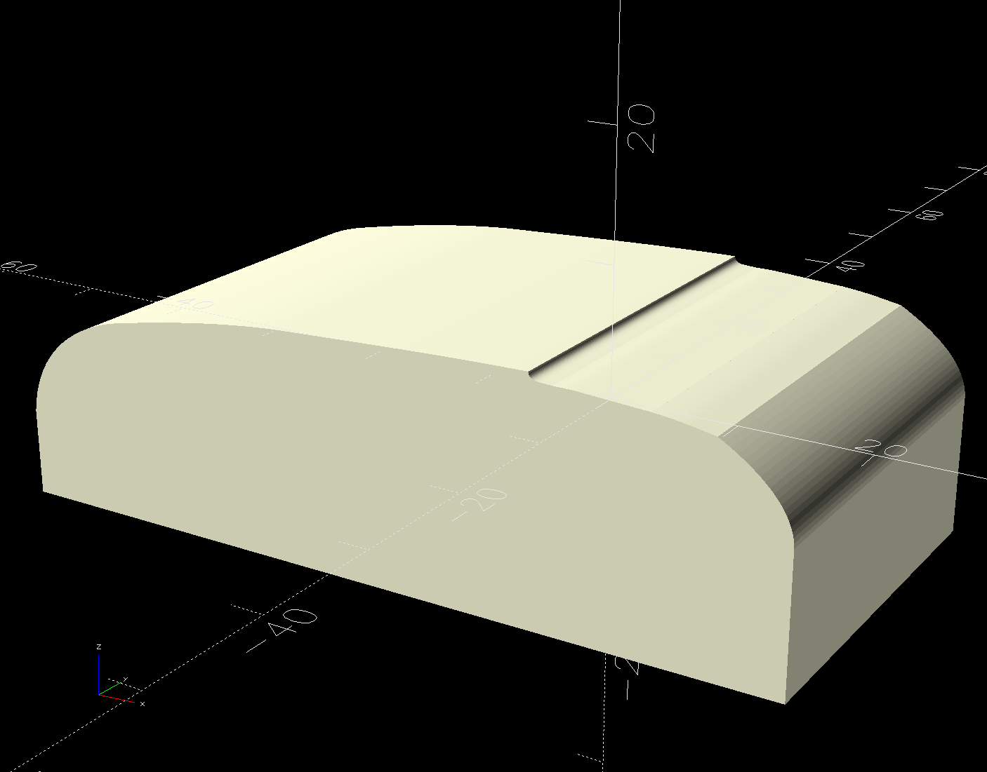
The solid model has three main pieces and a lock for the ribbon cable:
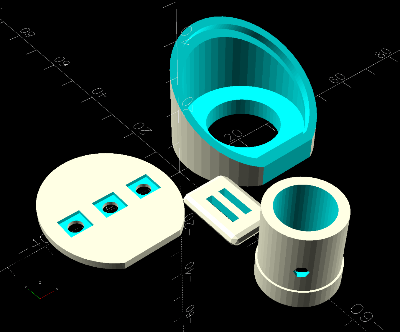
Those pockets keep the switches oriented while the glue cures.
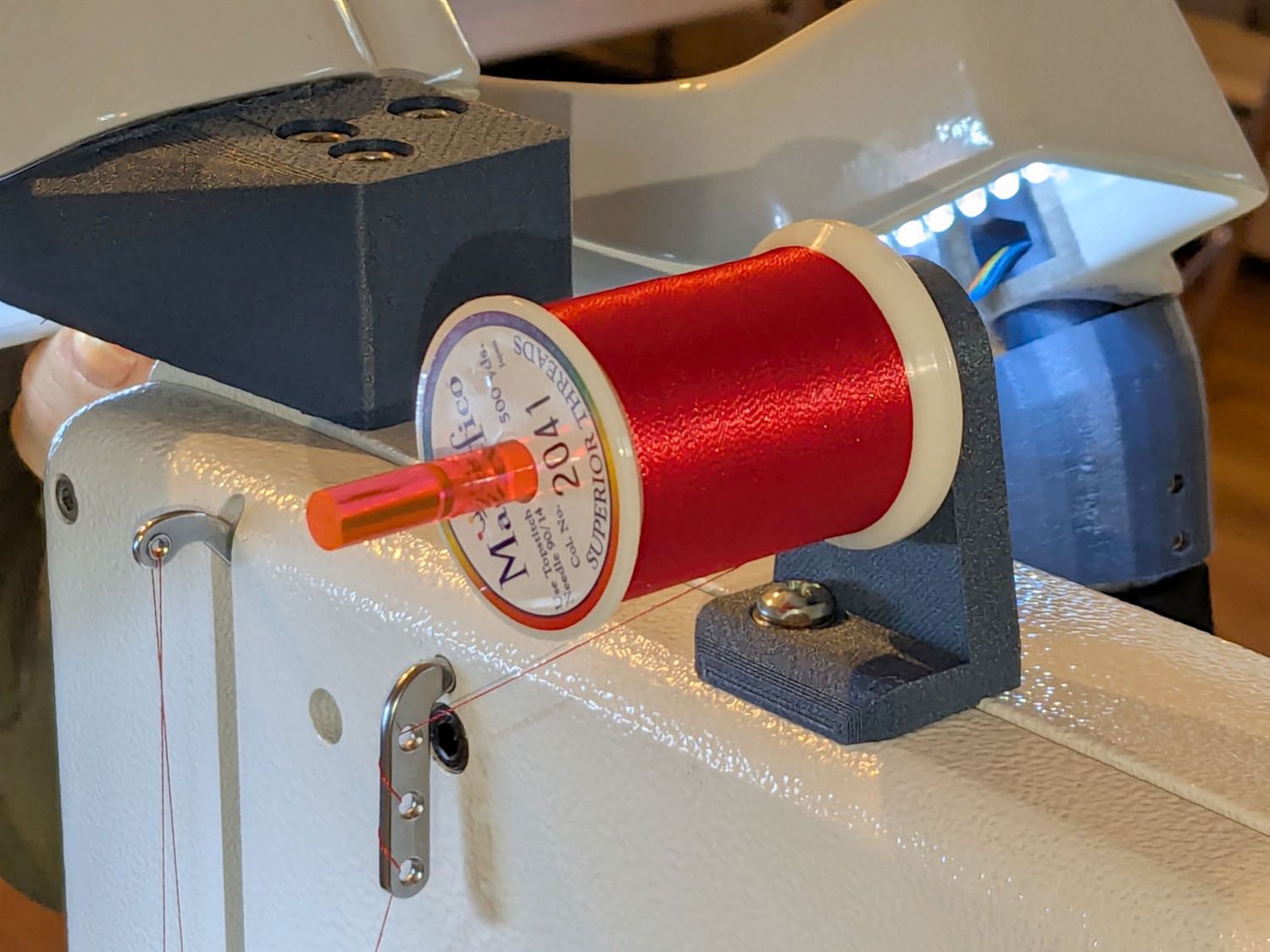
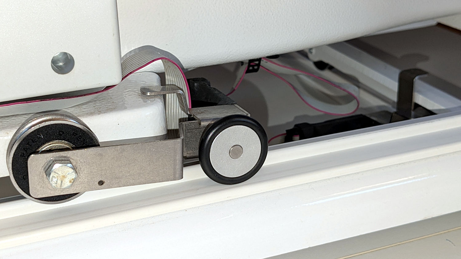
Two screws through the handlebar secure each cap. Handi-Quilter drove sheet metal screws into their OEM caps, distorting them enough to jam solidly into the handlebars. I’ve been reluctant to apply enough force to loosen them, so they remain frozen in place until the current quilt is done.
The new plugs have recesses for M3 square nuts to make them easily removable. As with the handlebar angle adapters, I’ll glue the plugs into the caps.
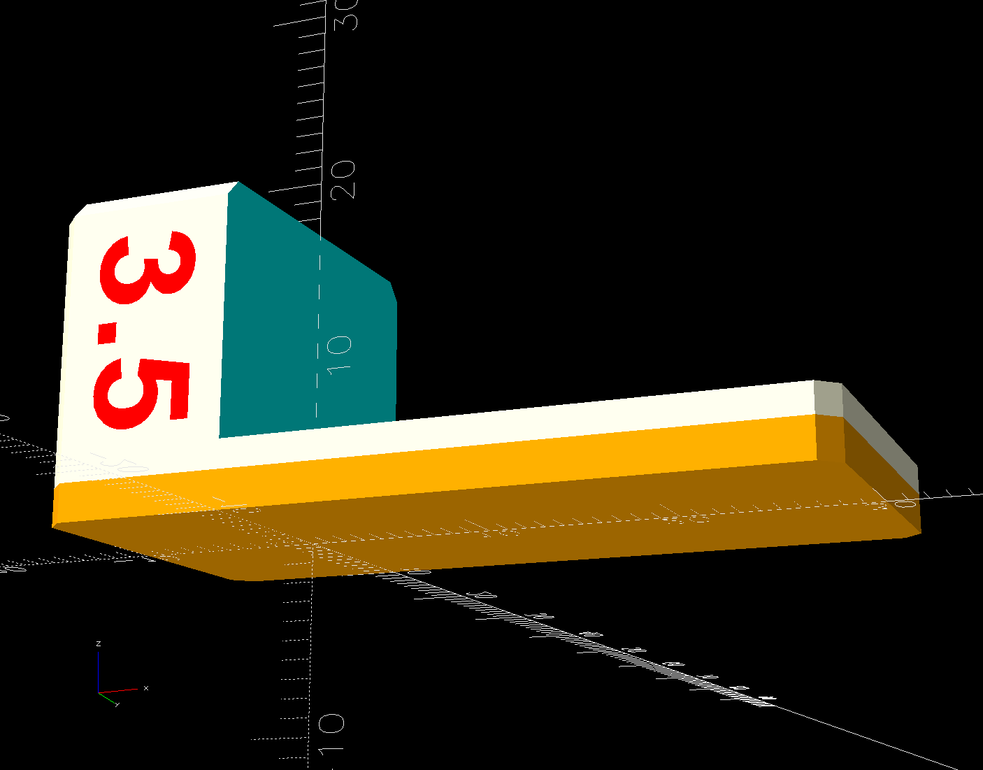
A slightly exploded view shows how the pieces fit together:
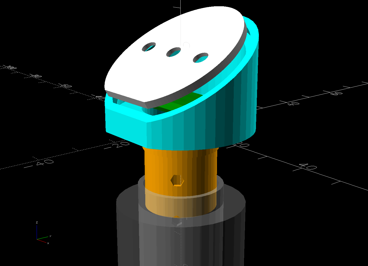
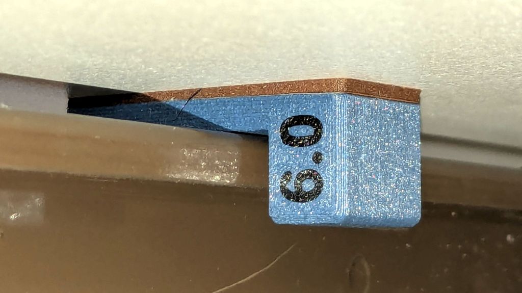
The switch plate sits recessed into the cap to allow room for the label (about which, more later):

The OpenSCAD source code as a GitHub Gist:
| // Handiquilter HQ Sixteen handlebar control button caps | |
| // Ed Nisley – KE4ZNU | |
| // 2025-04-05 | |
| include <BOSL2/std.scad> | |
| Layout = "Show"; // [Show,Build,Grip,Body,Face,FaceBack,Plug,CableLock] | |
| // Angle w.r.t. handlebar | |
| FaceAngle = 30; // [10:45] | |
| // Separation in Show display | |
| Gap = 5; // [0:20] | |
| /* [Hidden] */ | |
| HoleWindage = 0.2; | |
| Protrusion = 0.1; | |
| NumSides = 2*3*4; | |
| WallThick = 3.0; | |
| ID = 0; | |
| OD = 1; | |
| LENGTH = 2; | |
| Grip = [19.7,22.4,15.0]; // (7/8)*INCH = 22.2 mm + roughness, LENGTH=OEM insertion depth | |
| GripRadius = Grip[OD]/2; | |
| FoamOD = 34.0; // handlebar foam | |
| FoamRadius = FoamOD/2; | |
| SwitchBody = [6.3,6.3,4.0]; // does not include SMD leads | |
| SwitchStemOD = 3.5 + 2*HoleWindage; | |
| SwitchOC = 10.0; // center-to-center switch spacing | |
| LabelThick = 0.5; // laminated overlay | |
| FaceRim = 2.0; // rim around faceplate | |
| FaceThick = 2.0; // … plate thickness | |
| FaceDepth = FaceThick + LabelThick; // inset allowing for faceplate label | |
| CapOD = 38.0; // overall cap diameter | |
| CapTrim = FoamRadius; // flat trim on front | |
| CapBase = 5.0; // bottom thickness | |
| Cap = [FoamOD – FaceRim,CapOD,CapBase + CapOD*tan(FaceAngle)]; | |
| echo(Cap=Cap); | |
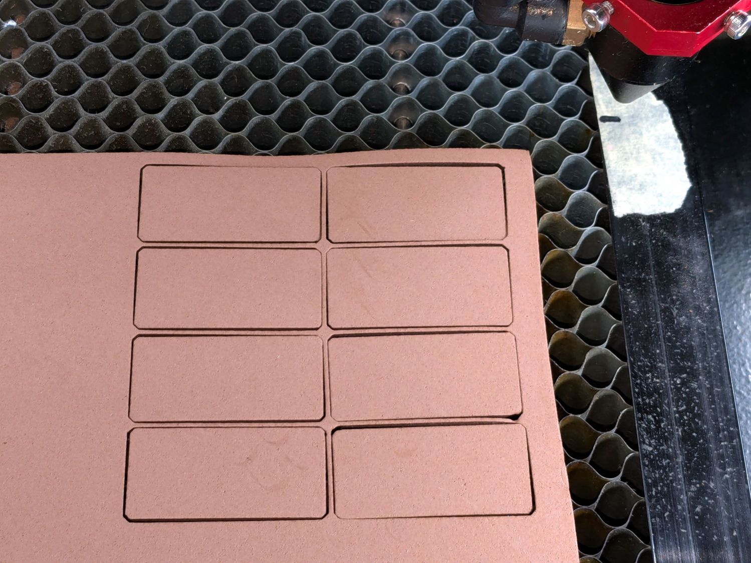
| TargetSize = 4.0; // laser alignment targets | |
| TargetsOC = [40.0,40.0]; | |
| Cable = [10.0,2.0,WallThick]; // aperture for cable lock | |
| ScrewAngles = [-45,45]; // mounting screws | |
| Screw = [2.0,3.0,7.0]; // OEM = sheet metal screw | |
| ScrewOffset = 6.0; // from top of grip tube | |
| SquareNut = [3.0,5.5,2.3 + 0.4]; // M3 square nut OD = side, LENGTH + inset allowance | |
| NutInset = GripRadius – sqrt(pow(GripRadius,2) – pow(SquareNut[OD],2)/4); | |
| PlugOA = [(Grip[ID] – 2*WallThick),(Grip[ID] – 1.0),(CapBase + ScrewOffset + 10.0)]; | |
| echo(PlugOA=PlugOA); | |
| //———- | |
| // Define objects | |
| //—– | |
| // Handlebar tube | |
| module GripTube() { | |
| difference() { | |
| tube(3*Grip[LENGTH],GripRadius,Grip[ID]/2,anchor=TOP); | |
| for (a = ScrewAngles) { | |
| down(ScrewOffset) zrot(a-90) | |
| right(GripRadius) | |
| yrot(90) cylinder(d=Screw[OD],h=Screw[LENGTH],center=true,$fn=6); | |
| } | |
| } | |
| } | |
| //—– | |
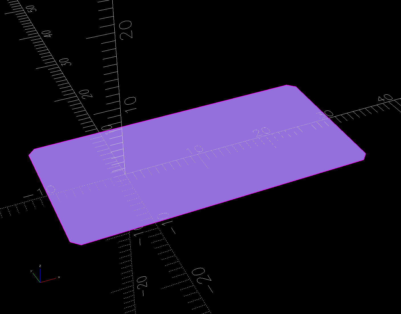
| // SVG outline of faceplate for laser cuttery | |
| module FaceShape(Holes=true,Targets=false) { | |
| difference() { | |
| scale([1,1/cos(FaceAngle)]) | |
| difference() { | |
| circle(d=(Cap[OD] – 2*FaceRim),$fn=144); | |
| fwd(CapTrim – FaceRim) | |
| square(Cap[OD],anchor=BACK); | |
| } | |
| if (Holes) | |
| for (i=[-1:1]) // arrange switch stem holes | |
| right(i*SwitchOC) | |
| zrot(180/8) circle(d=SwitchStemOD,$fn=32); | |
| } | |
| if (Targets) | |
| for (i = [-1,1], j = [-1,1]) | |
| translate([i*TargetsOC.x/2,j*TargetsOC.y/2]) | |
| square(2.0,center=true); | |
| } | |
| //—– | |
| // Faceplate backing sheet | |
| // Switch bodies indented into bottom, so flip to build | |
| module FacePlate(Thick=FaceThick,Holes=true) { | |
| difference() { | |
| linear_extrude(height=Thick,convexity=5) | |
| FaceShape(Holes); | |
| up(SwitchBody.z/4) | |
| for (i = [-1:1]) | |
| right(i*SwitchOC) | |
| cube(SwitchBody,anchor=TOP); | |
| } | |
| } | |
| //—– | |
| // Cap body | |
| module CapBody() { | |
| $fn=48; | |
| up(CapBase + (Cap[OD]/2)*tan(FaceAngle)) xrot(FaceAngle) | |
| difference() { | |
| xrot(-FaceAngle) | |
| down(CapBase + (Cap[OD]/2)*tan(FaceAngle)) | |
| difference() { | |
| cylinder(d=Cap[OD],h=Cap[LENGTH]); | |
| fwd(CapTrim) down(Protrusion) | |
| cube(2*Cap[LENGTH],anchor=BACK+BOTTOM); | |
| up(CapBase) | |
| difference() { | |
| cylinder(d=Cap[ID],h=Cap[LENGTH]); | |
| fwd(CapTrim – 2*FaceRim) | |
| cube(2*Cap[LENGTH],anchor=BACK+BOTTOM); | |
| } | |
| down(Protrusion) | |
| cylinder(d=Grip[ID],h=Cap[LENGTH]); | |
| } | |
| cube(2*Cap[OD],anchor=BOTTOM); | |
| down(FaceDepth) | |
| FacePlate(FaceDepth + Protrusion,Holes=false); | |
| } | |
| } | |
| //—– | |
| // Plug going into grip handlebar | |
| module CapPlug() { | |
| $fn=48; | |
| difference() { | |
| tube(PlugOA[LENGTH],id=PlugOA[ID],od=PlugOA[OD],anchor=BOTTOM) | |
| position(TOP) | |
| tube(CapBase,id=PlugOA[ID],od=Grip[ID],anchor=TOP); | |
| for (a = ScrewAngles) | |
| up(PlugOA.z – CapBase – ScrewOffset) zrot(a-90) | |
| right(PlugOA[ID]/2) | |
| yrot(90) { | |
| cube([SquareNut[OD],SquareNut[OD],SquareNut[LENGTH] + NutInset],center=true); | |
| zrot(180/6) | |
| cylinder(d=(SquareNut[ID] + 2*HoleWindage),h=PlugOA[ID],center=true,$fn=6); | |
| } | |
| } | |
| } | |
| //—– | |
| // Lock plate for ribbon cable | |
| module CableLock() { | |
| difference() { | |
| cuboid([2*Cable.x,PlugOA[ID],WallThick],rounding=WallThick/2,anchor=BOTTOM); | |
| for (j = [-1,1]) | |
| back(j*Cable.y) down(Protrusion) | |
| cube(Cable + [0,0,2*Protrusion],anchor=BOTTOM); | |
| } | |
| } | |
| //———- | |
| // Build things | |
| if (Layout == "Grip") { | |
| color("Silver",0.5) | |
| GripTube(); | |
| } | |
| if (Layout == "Face") | |
| FaceShape(Targets=true); | |
| if (Layout == "FaceBack") | |
| FacePlate(); | |
| if (Layout == "Body") | |
| CapBody(); | |
| if (Layout == "Plug") | |
| CapPlug(); | |
| if (Layout == "CableLock") | |
| CableLock(); | |
| if (Layout == "Show") { | |
| color("Green") | |
| up(CapBase) | |
| CableLock(); | |
| color("Orange") | |
| down(Gap) | |
| down(PlugOA[LENGTH] – CapBase) | |
| CapPlug(); | |
| color("Cyan",(Gap > 4)? 1.0 : 0.2) | |
| CapBody(); | |
| color("White",(Gap > 4)? 1.0 : 0.5) | |
| up(Gap*cos(FaceAngle)) fwd(Gap*sin(FaceAngle)) | |
| up(CapBase + (Cap[OD]/2)*tan(FaceAngle) – FaceDepth) | |
| back(FaceDepth*sin(FaceAngle)) xrot(FaceAngle) | |
| FacePlate(); | |
| down(3*Gap) { | |
| color("Silver",0.5) | |
| GripTube(); | |
| down(Gap) | |
| color("Gray",0.5) | |
| tube(3*Grip[LENGTH],FoamRadius,Grip[OD]/2,anchor=TOP); | |
| } | |
| } | |
| if (Layout == "Build") { | |
| right((Gap + Cap[OD])/2) | |
| CapBody(); | |
| left((Gap + Cap[OD])/2) | |
| zrot(180) up(FaceThick) xrot(180) | |
| FacePlate(); | |
| fwd(Gap + Cap[OD]) | |
| up(PlugOA[LENGTH]) xrot(180) zrot(180) | |
| CapPlug(); | |
| fwd(Cap[OD]/2) | |
| zrot(90) | |
| CableLock(); | |
| } |


