Ed Nisley's Blog: Shop notes, electronics, firmware, machinery, 3D printing, laser cuttery, and curiosities. Contents: 100% human thinking, 0% AI slop.
Tag: Improvements
Making the world a better place, one piece at a time
The mid-1950s wood doors on our house have wood storm doors with interchangeable wood-framed glass and screen panels. Twice a year, the diligent homeowner will swap the panels to match the season; during the last 60+ years, the glass panels remain undropped.
The back door has a diagonal tension brace to hold the door in shape; the door may be slightly distorted or the frame slightly out of square. In any event, the brace obstructs the panel, so the semiannual ritual includes loosening the brace and removing four screws. During the last 60+ years, the screw holes have required repair / filling several times; about five years ago, I plugged them with epoxy putty and drilled them to fit the screws.
That repair having aged out, I was about to renew the epoxy when I realized that I now have brass inserts that would work even better, if I replaced the original wood screws with 10-32 machine screws.
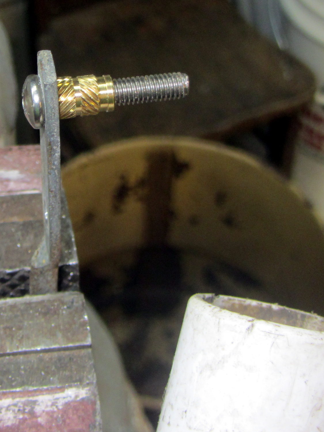
I cut the screws to the exact length using the brace and brass insert as a fixture:
Storm door – screw cutting
The vacuum cleaner nozzle to the lower right inhales the debris from the Dremel cutoff wheel that would otherwise fill the shop; I used up the last half of a wheel on four stainless steel screws.
Because each end of the brace has two screws, I knew that I couldn’t just drill out the four holes, plant four inserts, and be done with the job: the first insert on each end could go pretty nearly anywhere, but the second insert must match the brace hole spacing. The only way I know how to do that is to epoxy the first two inserts in place and let them cure, drill the other two holes slightly oversize, mount those inserts on the brace, butter them with epoxy, put the brace in place, tighten the first two screws, snug the brace, and hope I didn’t epoxy the brace to the door or the screws to the inserts.
Slips of waxed paper between the brace and the door prevented the first problem and oiling the screws prevented the second. It’s not the best-looking job I’ve ever done, but nobody will ever see the inserts behind the brace:
Storm door – inserts
Now, we’re ready for winter and I’m ready for spring!
Most likely, the new owners (whoever and whenever they may be) will never use these inserts, as they’ll replace all the windows & doors, plus sand & refinish the hardwood floors, before moving in …
A long long time ago, we bought a kitchen spatula that’s served us well ever since:
Spatula Search – original
To give you an idea of how old that poor thing is, the back of the handle bears a Japan stamp. I’ve re-set the rivets several times, the blade has rusted as badly as you think, and we recently, very reluctantly, decided it has passed its best-used-by date.
The 3 x 4.5 inch blade is 19 mil = 0.45 mm plated carbon steel, stiff enough to remain flat and springy enough to bend a little, with a 9 inch = 230 mm steel handle ending in a plastic overmold.
These days, it’s essential to the cutting, flipping, and serving of the morning’s omelet-like substance, made of eggs, bacon, veggies, green leafy things, plus this-and-that, in the cast-iron pan. Mary chops the disk into quarters with the reasonably sharp edge, maneuvers the reasonably bendy blade under each quarter, flips them over, tops with bacon & cheese, pauses for consolidation & melting, then pops them onto plates. Yum!
Omelet in cast-iron pan
So we set out to buy a replacement.
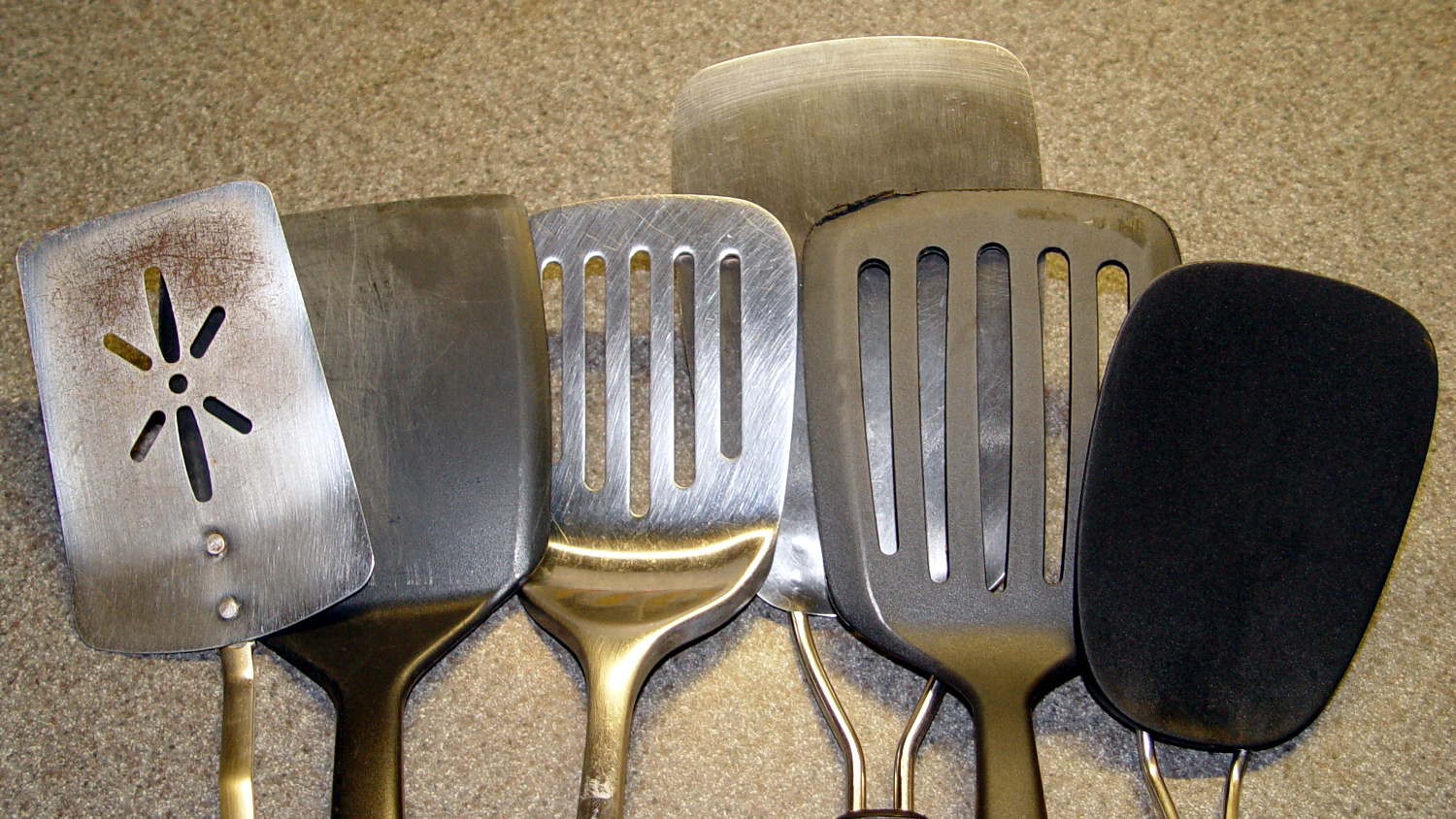
Here’s what we’ve tried and rejected so far:
Spatula Search – overview
I’ve used this one for many years to flip pancakes on a succession of non-stick griddles, a service at which it excels. The edge isn’t sharp enough to cut the green-and-leafy and the completely inflexible blade cannot be maneuvered under the omelet quarters:
Spatula Search – heavy solid plastic
This one gets deployed for burgers and their ilk, also in the cast-iron pan. The blade, although sharp enough, is completely rigid:
Spatula Search – heavy slotted metal
On the other paw, a slightly concave 7 mil = 0.18 mm spring steel blade is much too thin and, well, springy. Although very sharp, you cannot apply enough cutting force without suddenly bending the blade and, if the omelet quarter isn’t positioned exactly right, the blade will bend underneath it and dump breakfast on the stovetop. The alert reader will notice a missing weld between the blade and the bottom wire handle:
Spatula Search – thin spring steel
This very thin plastic blade has similar problems with poor cut-ability and excessive flexibility:
Spatula Search – thin springy plastic
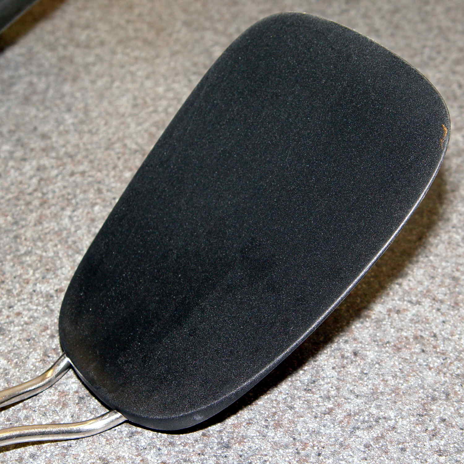
This one looked really promising and worked almost perfectly. Regrettably, its nylon blade bears a 400 °F rating and the bottom of the omelet reaches nearly 450 °F. You can see what happens to the reasonably sharp edge as it scrapes across the pan:
Spatula Search – heavy slotted nylon
The omelet cooks at the temperature it cooks at, which part of the specifications is not subject to further discussion.
So, we’re stumped. Having trawled the usual online and big-box stores, we’ve been unable to find a replacement. Simple steel blades aren’t available. Trendy silicone-bonded stainless steel blades combine the worst of all worlds: won’t cut and won’t flip. Pretty nearly anything you don’t see above seems obviously unsuitable for our simple needs: too big, too small, or too melty.
We’ll consider all recommendations and suggestions! Thanks …
One of the Hobo dataloggers asked for a new battery during its most recent data dump. The old battery dates back to January 2015:
Maxell CR2032 lithium cell – 22 month life
That was when a batch of Energizer cells failed in quick succession: it wasn’t the datalogger’s fault. I’ve been handling the cells a bit more carefully, too, although that certainly doesn’t account for the much longer life.
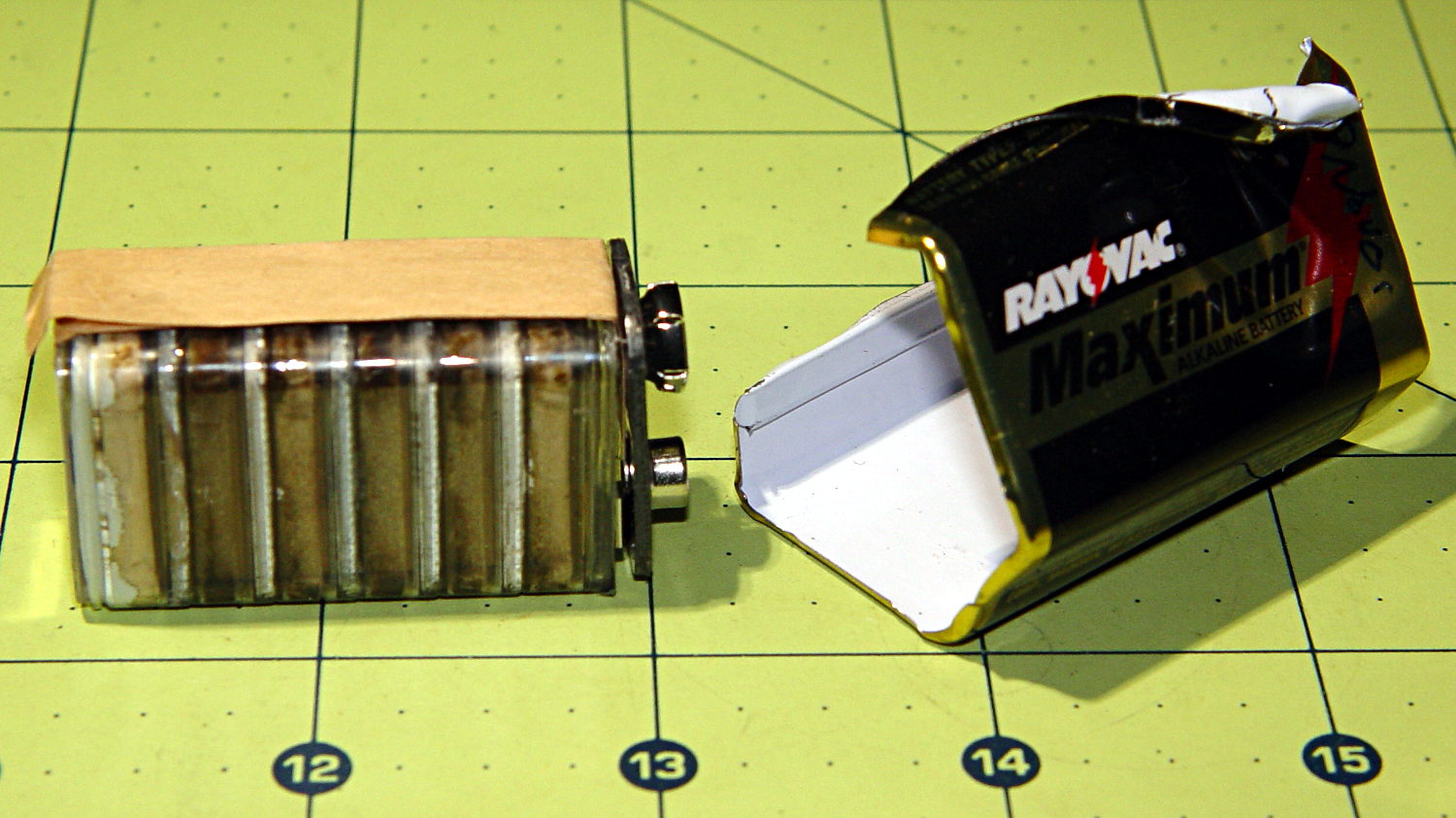
It occurred to me that I should dismantle a defunct Rayovac Maximum 9 V alkaline battery from the most recent batch (*) to see what it looked like:
Rayovac Maximum 9V battery – interior
Surprise!
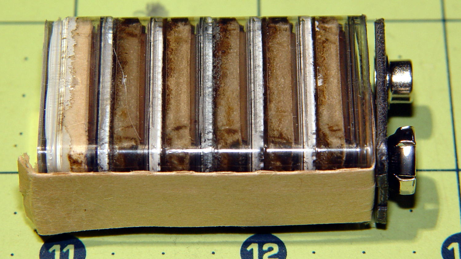
A closer look at those pancake cells:
Rayovac Maximum 9V battery – detail
They look like separate cells bonded into a stack, although there’s no easy way to probe the inter-cell contacts; the leftmost cell probably died first.
(*) Which has apparently outlived the Rayovac Maximum brand, as they don’t appear on the Rayovac site.
Mary’s new half-gallon sprayer arrived with a kink in the hose just below the handle, which is about what you’d expect from a non-reinforced plastic tube jammed into the smallest possible box containing both the sprayer and its wand. Fortunately, the Box o’ Springs had one that just fit the hose and jammed firmly into the handle:
Sprayer hose with kink-resisting spring
The kink slowly worked its way out after being surrounded by the spring and shouldn’t come back.
My Raspberry Pi-based streaming radio player generally worked fine, except sometimes the keypad / volume control knob would stop responding after switching streams. This being an erratic thing, the error had to be a timing problem in otherwise correct code and, after spending Quality Time with the Python subprocess and select doc, I decided I was abusing mplayer’s stdin and stdout pipes.
This iteration registers mplayer’s stdout pipe as Yet Another select.poll() Polling Object, so that the main loop can respond whenever a complete line arrives. Starting mplayer in quiet mode reduces the tonnage of stdout text, at the cost of losing the streaming status that I really couldn’t do anything with, and eliminates the occasional stalls when mplayer (apparently) dies in the middle of a line.
The code kills and restarts mplayer whenever it detects an EOF or stream cutoff. That works most of the time, but a persistent server or network failure can still send the code into a sulk. Manually selecting a different stream (after we eventually notice the silence) generally sets things right, mainly by whacking mplayer upside the head; it’s good enough.
It seems I inadvertently invented streaming ad suppression by muting (most of) the tracks that produced weird audio effects. Given that the “radio stations” still get paid for sending ads to me, I’m not actually cheating anybody out of their revenue: I’ve just automated our trips to the volume control knob. The audio goes silent for a few seconds (or, sheesh, a few minutes) , blatting a second or two of ad noise around the gap to remind us of what we’re missing; given the prevalence of National Forest Service PSAs, the audio ad market must be a horrific wasteland.
This file contains hidden or bidirectional Unicode text that may be interpreted or compiled differently than what appears below. To review, open the file in an editor that reveals hidden Unicode characters.
Learn more about bidirectional Unicode characters
The original SuperFormula equation produces points in polar coordinates, which the Chiplotle library converts to the rectilinear format more useful with Cartesian plotters. I’ve been feeding the equation with 10001 angular values (10 passes around the paper, with 1000 points per pass, plus one more point to close the pattern), which means the angle changes by 3600°/10000 = 0.36° per point. Depending on the formula’s randomly chosen parameters, each successive point can move the plotter pen by almost nothing to several inches.
On the “almost nothing” end of the scale, the plotter slows to a crawl while the serial interface struggles to feed the commands. Given that you can’t see the result, why send the commands?
Computing point-to-point distances goes more easily in rectilinear coordinates, so I un-tweaked my polar-modified superformula function to return the points in rectangular coordinates. I’d originally thought a progressive scaling factor would be interesting, but it never happened.
The coordinate pruning occurs in the supershape function, which now contains a loop to scan through the incoming list of points from the superformula function and add a point to the output path only when it differs by enough from the most recently output point:
The first and last points always go into the output list; the latter might be duplicated, but that doesn’t matter.
Note that you can’t prune the list by comparing successive points, because then you’d jump directly from the start of a series of small motions to their end. The idea is to step through the small motions in larger units that, with a bit of luck, won’t be too ugly.
The width and height values scale the XY coordinates to fill either A or B paper sheets, with units of “Plotter Units” = 40.2 PU/mm = 1021 PU/inch. You can scale those in various ways to fit various output sizes within the sheets, but I use the defaults that fill the entire sheets with a reasonable margin. As a result, the magic number 60 specifies 60 Plotter Units; obviously, it should have a suitable name.
Pruning to 40 PU = 1.0 mm (clicky for more dots, festooned with over-compressed JPEG artifacts):
Plot pruned to 40 PU
Pruning to 60 PU = 1.5 mm:
Plot pruned to 60 PU
Pruning to 80 PU = 2.0 mm:
Plot pruned to 80 PU
Pruning to 120 PU = 3.0 mm:
Plot pruned to 120 PU
All four of those plots have the same pens in the same order, although I refilled a few of them in flight.
By and large, up through 80 PU there’s not much visual difference, although you can definitely see the 3 mm increments at 120 PU. However, the plotting time drops from just under an hour for each un-pruned plot to maybe 15 minutes with 120 PU pruning, with 60 PU producing very good results at half an hour.
Comparing the length of the input point lists to the pruned output path lists, including some pruning values not shown above:
Eyeballometrically, 60 PU pruning halves the number of plotted points, so the average data rate jumps from 9600 b/s to 19.2 kb/s. Zowie!
Most of the pruning occurs near the middle of the patterns, where the pen slows to a crawl. Out near the spiky rim, where the points are few & far between, there’s no pruning at all. Obviously, quantizing a generic plot to 1.5 mm would produce terrible results; in this situation, the SuperFormula produces smooth curves (apart from those spikes) that look just fine.
This file contains hidden or bidirectional Unicode text that may be interpreted or compiled differently than what appears below. To review, open the file in an editor that reveals hidden Unicode characters.
Learn more about bidirectional Unicode characters