Ed Nisley's Blog: Shop notes, electronics, firmware, machinery, 3D printing, laser cuttery, and curiosities. Contents: 100% human thinking, 0% AI slop.
Tag: Improvements
Making the world a better place, one piece at a time
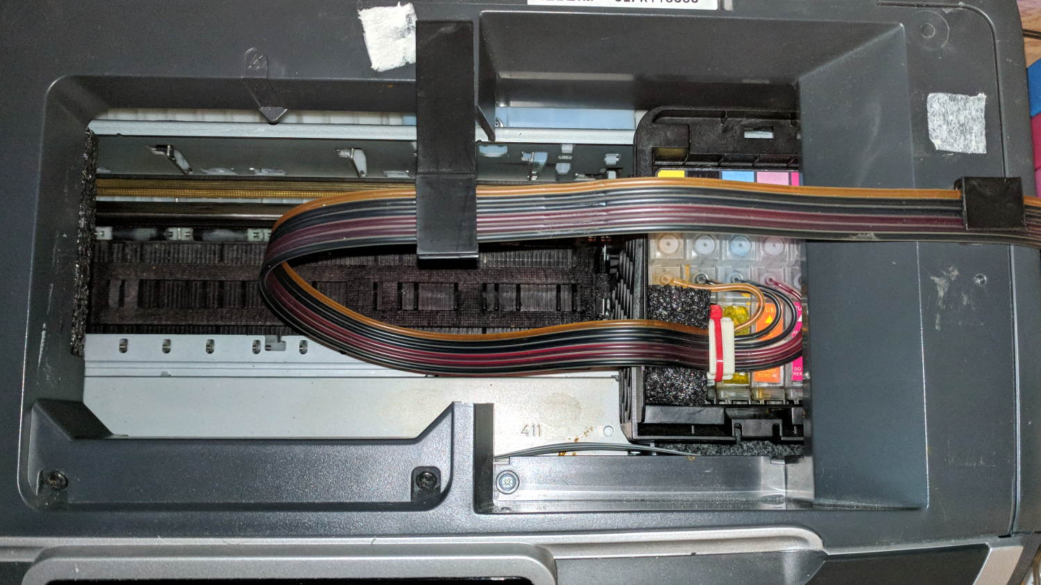
After fixing the yellow ink tube, the Epson R380 printer occasionally gave off a horrible clunk as the tubes slapped around inside the frame. This routing seems much quieter and, as you can see from the marks on the tubes, leaves much less free to flop around:
Epson R380 Printer – CISS tube routing
I cut a small collar (to the left of the white block with the red cable tie) to guide the tubing up over the edge of the ink cartridge holder, with a ramp from the upper edge and raised edges to hold the tubes in place, from a block of black closed-cell foam. It seems perfectly happy to do its job without anything other than the tubes holding it in place atop the cartridges.
There’s also a block of foam filling a gap under the printer’s top frame member (along the far left edge of the picture) to cushion the tubes as they whack against the edge.
So far, so good.
I’ve dumped a few more tanks of waste ink down the drain. When this printer eventually gives up, I’ll get a color laser and move on.
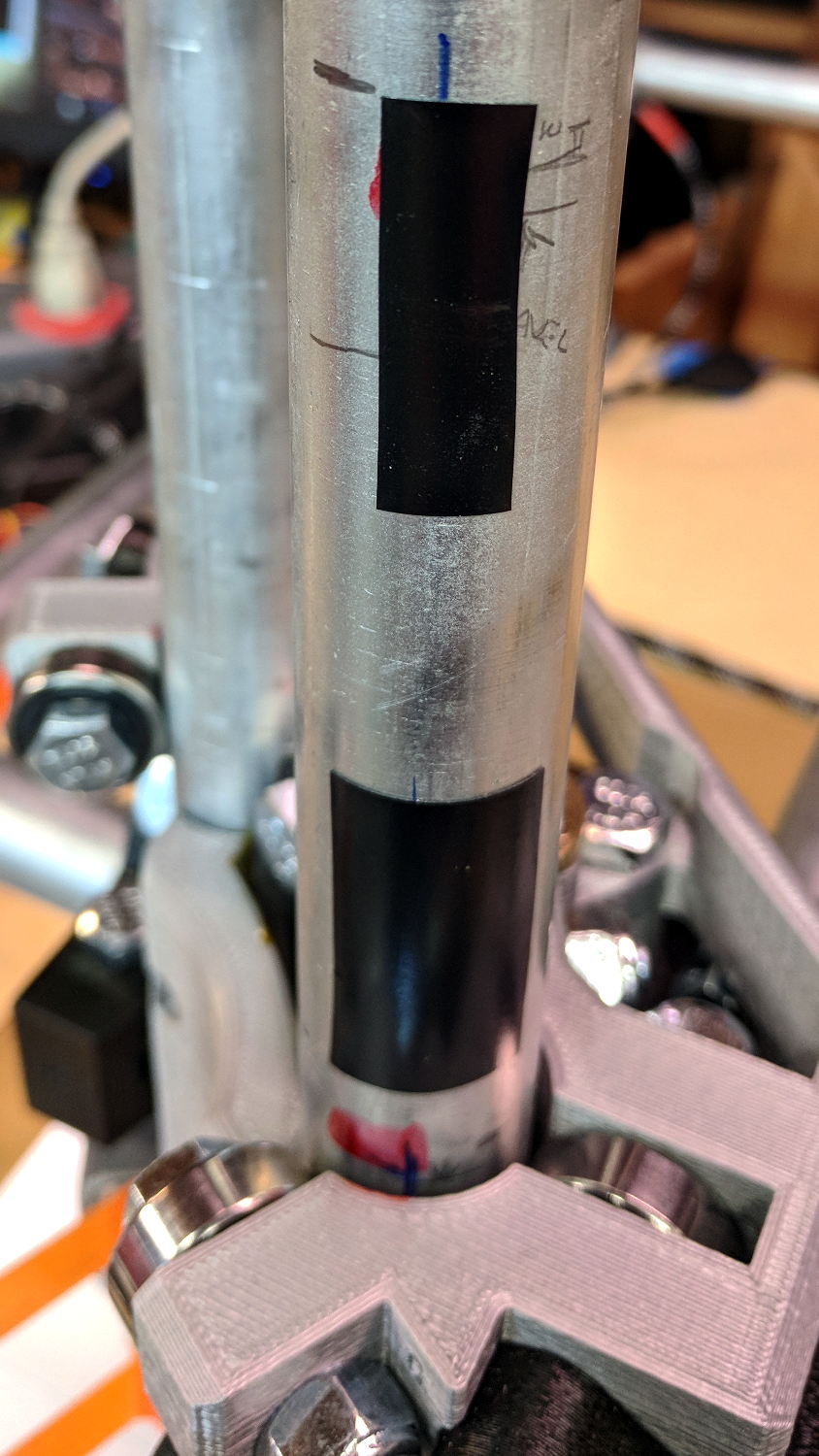
Homing the MPCNC’s Z axis at the bottom end of its travel made no sense, but the Z stage lacks a convenient spot to mount / trigger a switch at the top of its travel, so this sufficed for initial tests & fiddling:
MPCNC – Z min endstop
The EMT rail carrying the switch moves downward, tripping the lever when it hits the MPCNC’s central assembly.
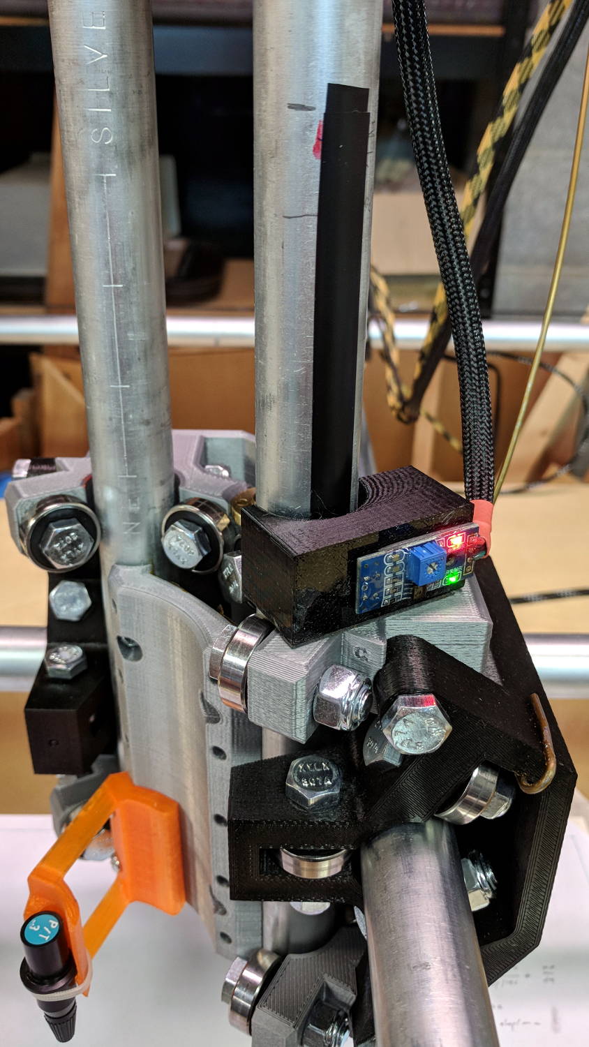
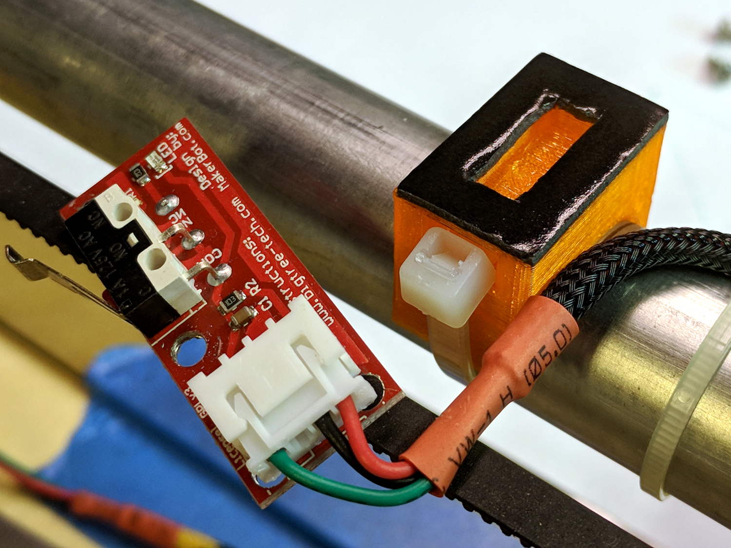
Somewhat to my surprise, a TRCT5000-based optical proximity sensor (harvested from the Kenmore 158 Crash Test Dummy’s corpse) and a strip of black electrical tape work perfectly:
I soldered the wires (harvested from the previous endstop) directly to the PCB, because the pinout isn’t the same and fewer connectors should be better.
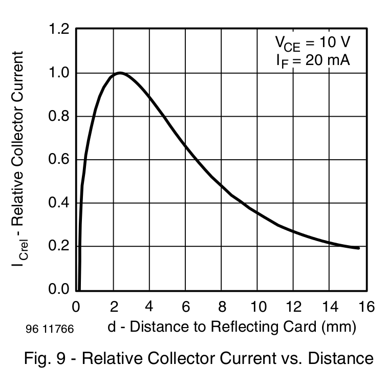
The mount uses black PETG, rather than translucent orange, in hope of IR opacity, and wraps around the EMT rail at (roughly) the 2 mm standoff producing the peak response:
IR Reflective Sensor module – TCRT5000 – response vs distance
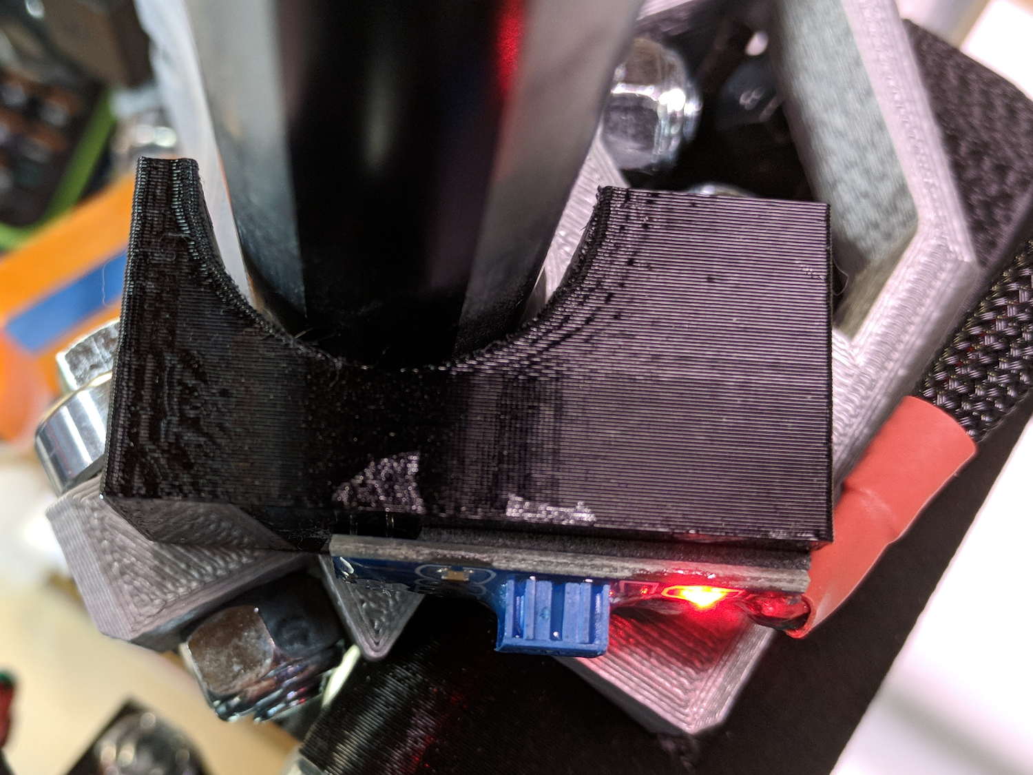
In truth, I set the gap by eyeballometric guesstimation to make the entire mount arc sit equidistant from the EMT:
MPCNC – Z Opto Prox Endstop – top view
The mount includes the 2 mm spacing around the EMT OD and puts the sensor tip flush with the arc OD, so it should be pretty close:
TCRT5000 Z Axis Endstop Mount – solid model
A strip of 3M permanent tape, cut to clear the 608 bearings, affixes the mount to the MPCNC’s central assembly. The solid model now includes a midline reference notch, with a height rounded up to the next-highest multiple of 2.0 mm. It needs a loop to anchor the cable.
The blue twiddlepot sets the comparator threshold midway between the response over black tape (incorrectly on = too low) and bare EMT (incorrectly off = too high), in the hope of noise immunity. The range spanned nearly half of the pot rotation, so I think it’s all good.
The sensor doesn’t trip when the edge of the tape exactly meets its midline, which meant I had to trim a strip of tape to suit. As part of setting the twiddlepot, I shut off the Z axis motor and laid some test strips on the EMT:
MPCNC – Z Axis Opto Prox Endstop – Test Tape
I spun the leadscrew with one hand, held the sensor with the other, twiddled the trimpot, trimmed the upper and lower ends of the tape, and generally had a fine time. The sensor responds equally well to a half-wide strip of tape (in the upper picture), with the distinct advantage of not encroaching on the 608 bearing tracks.
The GRBL setup now homes Y and Z toward the positive end of their travel, with X still toward the negative end while a set of extension cables remains in transit around the planet.
This file contains hidden or bidirectional Unicode text that may be interpreted or compiled differently than what appears below. To review, open the file in an editor that reveals hidden Unicode characters.
Learn more about bidirectional Unicode characters
Using 3D printer style endstop switches has the advantage of putting low-pass filters (i.e. caps) at the switches, plus adding LED blinkiness, but it does leave the +5 V and Gnd conductors hanging out in the breeze. After mulling over various enclosures, it occured to me I could just entomb the things in epoxy and be done with it.
The first step was to get rid of the PCB mounting screws and use 3M permanent foam tape:
MPCNC – Epoxy-coated Endstop – Adhesive Tape
Get all the switches set up and level, mix up 2.8 g of XTC-3D (because I have way too much), and dab it on the switches until all the exposed conductors have at least a thin coat:
MPCNC – Epoxy-coated Endstop – Installed
You should use a bit more care than I: the epoxy can creep around the corner of the switch and immobilize the actuator in its relaxed position. Some deft X-Acto knife work solved the problem, but only after firmly smashing the X axis against the nonfunctional switch.
Epoxy isn’t a particularly good encapsulant, because it cures hard and tends to crack components off the board during temperature extremes. These boards live in the basement, cost under a buck, and I have plenty of spares, so let’s see what happens.
At least it’s now somewhat more difficult to apply a dead short across the Arduino’s power supply, which comes directly from a Raspberry Pi’s USB port.
GRBL responds to critical errors by disabling its outputs, which seems like a useful feature for a big-enough-to-hurt CNC machine like the MPCNC. Unlike the RAMPS 1.4 board, there’s no dedicated power-control pin, so I connected the Coolant output to the same DC-DC SSR I tried out with the RAMPS board:
MPCNC – CNC Shield – Power SSR
With homing enabled, GRBL emerges from power-on resets and error conditions with the spindle and coolant turned off and the G-Code interpreter in a locked state requiring manual intervention, so turning the stepper power on fits right in:
$x – Unlock the controls
m8 – Coolant output on = enable stepper power
$h – Home all axes
The steppers go clunk as the power supply turns on, providing an audible confirmation. The dim red LED on the SSR isn’t particularly conspicuous.
Turning the stepper power off:
m9 – Coolant output off = disable stepper power
I think the A4988 drivers maintain their microstep position with the stepper power supply off, because their logic power remains on. In any event, you probably wouldn’t want to restart after an emergency stop without clearing the fault and re-homing the axes.
The board has Cycle Start, Feed Hold, and Abort inputs just crying out for big colorful pushbutton switches.
Unlike the RAMPS board, the Prontoneer CNC Shield does not feed stepper power to the underlying Arduino UNO, leaving it safely powered by USB or the coax jack.
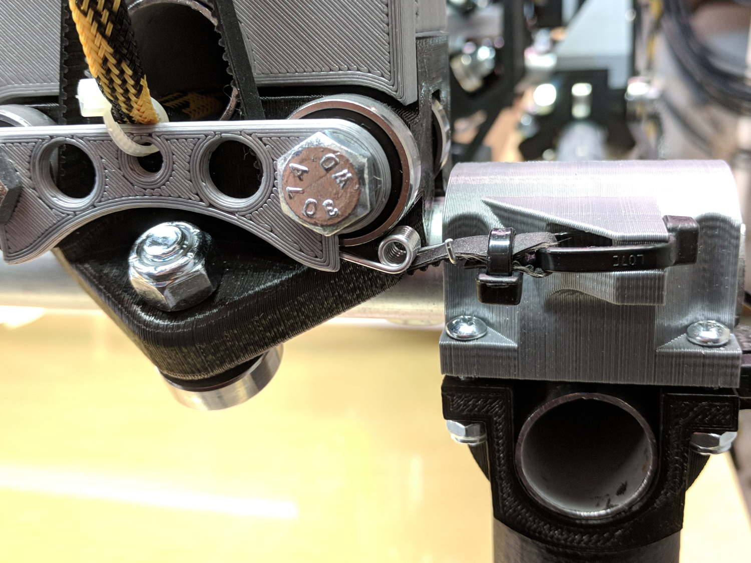
The MPCNC has the entire weight of the Z axis motor and stage resting on the leadscrew, so the instructions call for preloading the spring coupler by stretching it with the leadscrew butted against the motor shaft. The leadscrew end isn’t particularly flat, so I inserted a 1/4 inch ball bearing between the two before the stretch:
MPCNC – Z Axis leadscrew – coupler bearing
I’m reasonably sure the ball won’t make the slightest difference, but two slightly misaligned shafts can now pivot on a point, rather than grind against each other. There’s no evidence of misalignment; I feel better and that’s what counts.
The GT2 / GT3 belt specs call for 10-ish pounds of tension, but I don’t yet have a good feel for the actual MPCNC belt tension … and it’s hard to measure in-situ. So I picked up some spring tensioners and yanked one with a luggage scale:
GT2 Belt Tensioner – 4 kg
You’re looking at 4 kg = 8-ish pounds of tension. When they’re relaxed, the arms sit at roughly right angles.
I installed them on the far end of the belts, although that’s a bit snug under the roller:
GT2 Belt Tensioner – installed
An endstop switch will eventually add some clearance and it’ll be all good.
Even though they’re neither linear nor precisely calibrated, they’ll serve as a reminder to check the tension every now and again.
Install them with the same casual disregard you reserve for fish hooks and you’ll emerge unscathed.
The Protoneer CNC Shield has headers for two endstops on each axis, although they’re wired to the same Arduino input pin. I installed a pair of Makerbot-style endstops on the Y axis, plugged them in, triggered one, and … the Arduino crashed. Hard. As in, a complete loss of power and reboot.
Some fiddling around produced absolutely baffling symptoms, as I replaced each endstop board and their cables to no avail.
Perusing the schematic (the “full instructions” link is dead, of course) eventually revealed the problem:
Makerbot style endstop – schematic
Got it?
Although there’s a pullup on the COM switch terminal, the switch’s NC terminal is connected to the +5 V supply, shorting across the both resistor and the LED+resistor. With two endstops in parallel, triggering one crowbars the other’s power supply to ground. I’m sure it made sense at the time, perhaps by ensuring no possible noise source could interfere with the pullup.
The solution is simple: disconnect the NC terminal from the power supply. As it turns out, the PCB layout routes +5 V on the bottom layer, up through the via around the NC switch terminal, thence to the LED and resistor, leaving only one choice:
MPCNC – dual MG endstop hack
Yup, amputate the NC terminal and be done with it.
After that, the pullup resistor lets the endstops cooperate like you’d expect: triggering either one lights up both LEDs.