A flash gun is hard to beat for straight-up nostalgia:

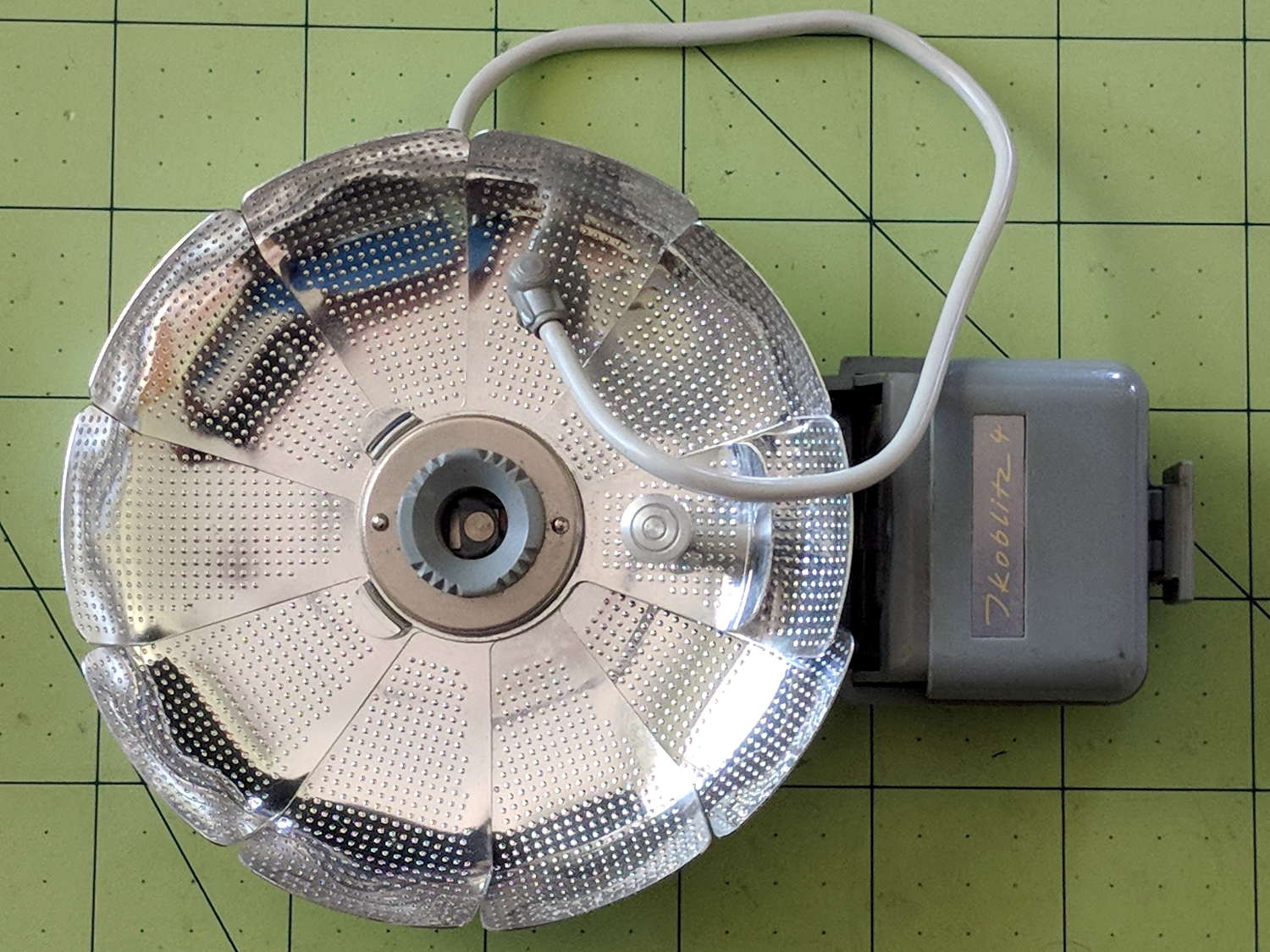
This Zeiss Ikon Ikoblitz 4 is in fine shape:

And no more grubby than one might expect after all those decades:

I distinctly remember Flash Guide Numbers:

The red dial scale has the Guide Numbers (aperture × feet) and the lower black dial scale gives the lens apertures. The manual doesn’t mention the black figures above the red Guide Numbers; they’re metric Guide Number (aperture × meters), which would have been obvious back in the day.
The tidy shell slides off when you release a latch in the back:

Then the reflector unfurls:
Mirabile dictu, the previous owner removed the 15 V “hearing aid” battery (Eveready 504, 60 mA·h in the 504A alkaline version) before storing the flash, leaving the contacts in pristine condition:
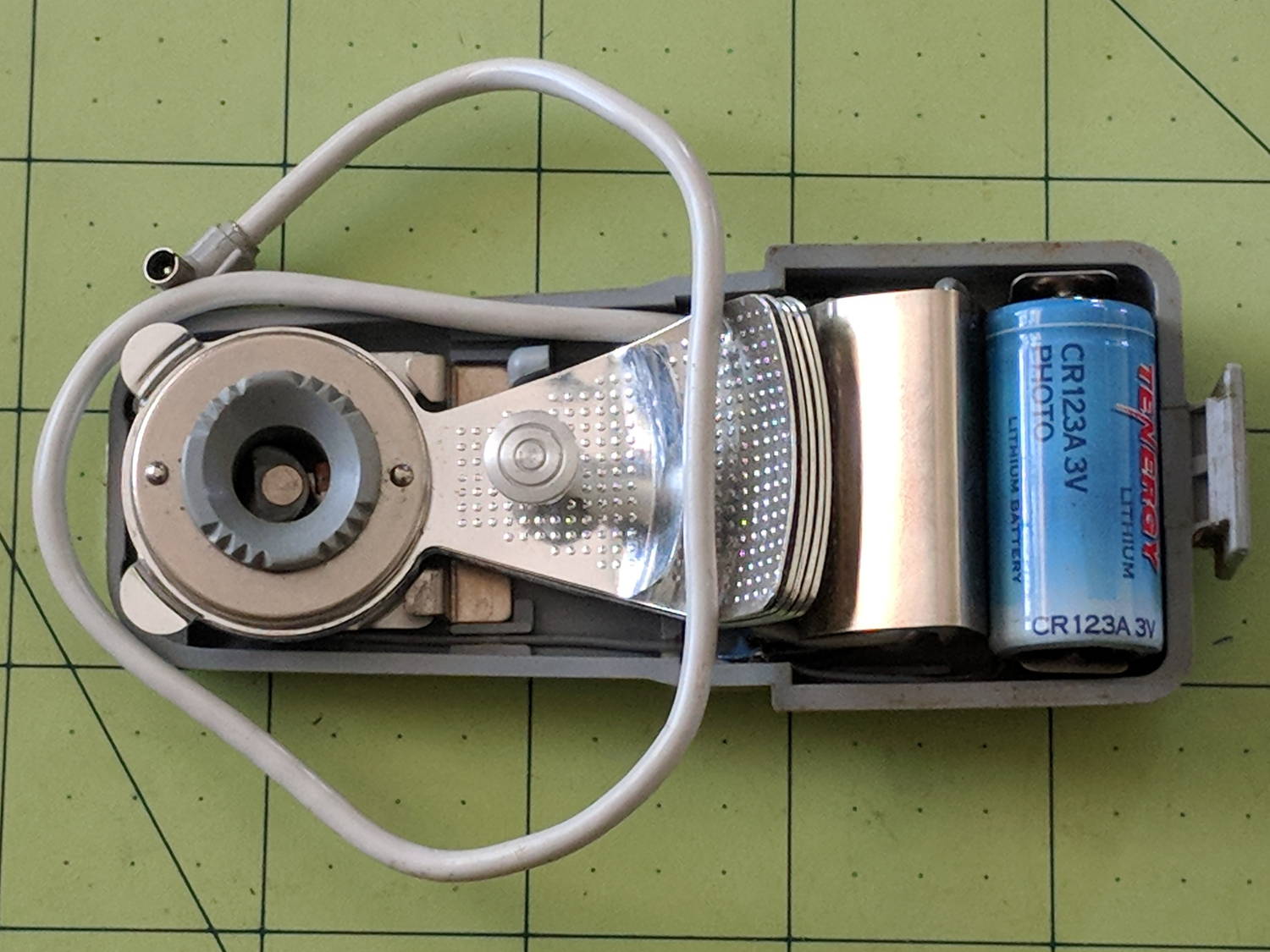
A 3 V CR123A primary lithium cell snaps perfectly into the battery holder, which I define as a Good Omen: a dab of circuitry could turn this into self-powered and highly attractive Art. This would be one of the very few applications well-suited for the coldest blue-white LEDs.
One could adapt an A23 12 V alkaline battery (33 mA·h) to the holder, at the cost of half the capacity.
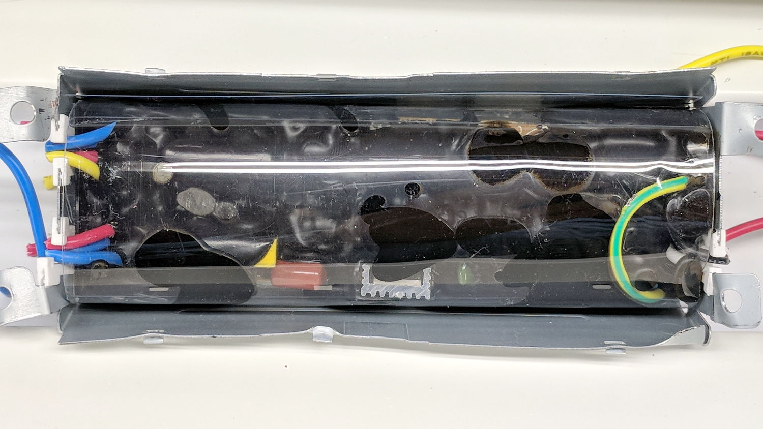
The silver shield just to the left of the battery conceals a 250 μF (!) nonpolarized capacitor.
One could build a bayonet-base (GE #5 / Press 25) adapter or poke a doodad with a 9 mm cylindrical base into the M2 bulb adapter (unrelated to my M2 printer):

Herewith, the Zeiss Ikon Ikoblitz 4 – Instruction Manual, should you need more details.
This hardware may be a progenitor of Gibson’s vat-grown Zeiss Ikon eyes.