Ed Nisley's Blog: Shop notes, electronics, firmware, machinery, 3D printing, laser cuttery, and curiosities. Contents: 100% human thinking, 0% AI slop.
Tag: Improvements
Making the world a better place, one piece at a time
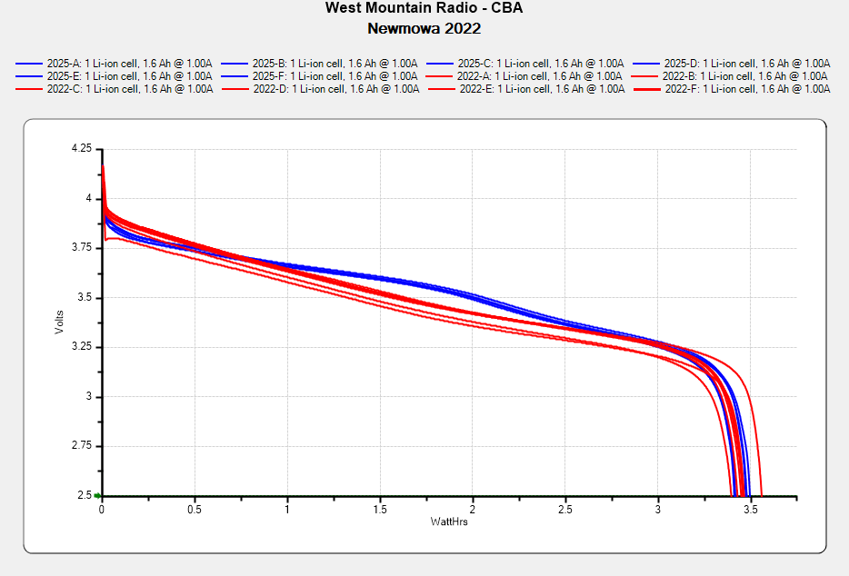
I don’t know what the bump in the middle of the new battery discharge curve means. Something weird in the chemistry, I suppose. Getting good batteries from Amazon surely remains a crapshoot and I now have four chargers.
Recharging all six batteries required 5488 mA·hr, just over 900 mA·hr apiece. Running the camera on a one-hour bike ride burns 600-ish mA·hr, so that’s comforting.
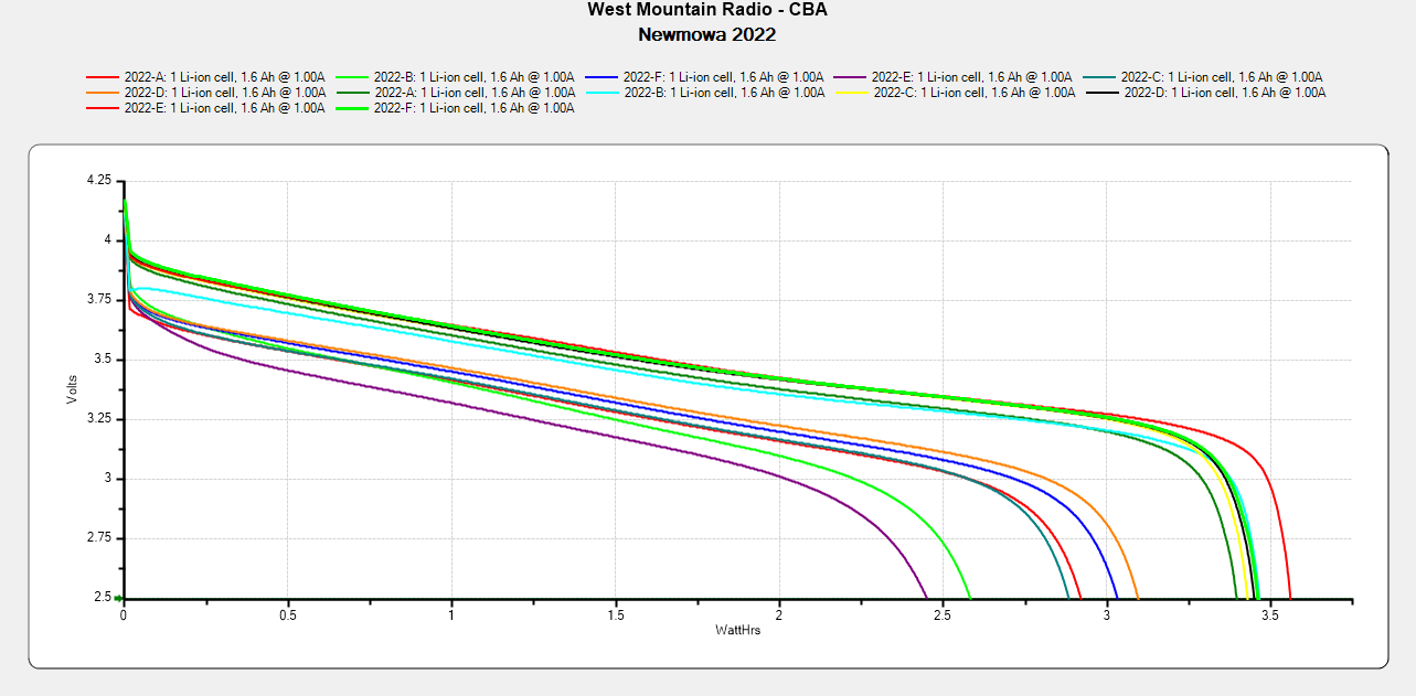
Comparing the new results with the 2022 batteries tested last month:
NP-BX1 – Newmowa 2022 in 2025-06
The upper traces appear in red in the first plot, the lower curves come from three years of use.
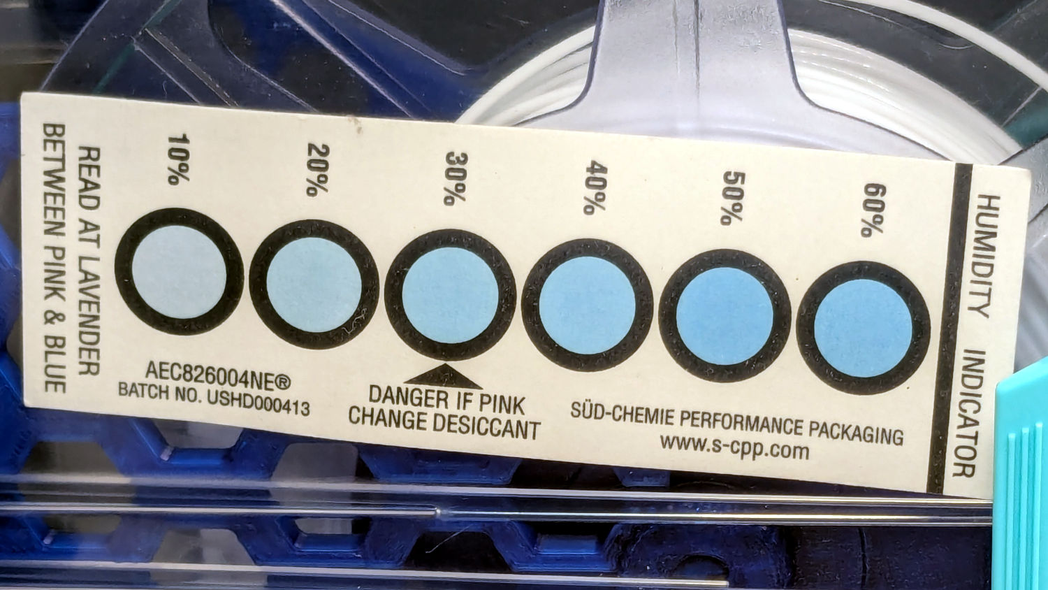
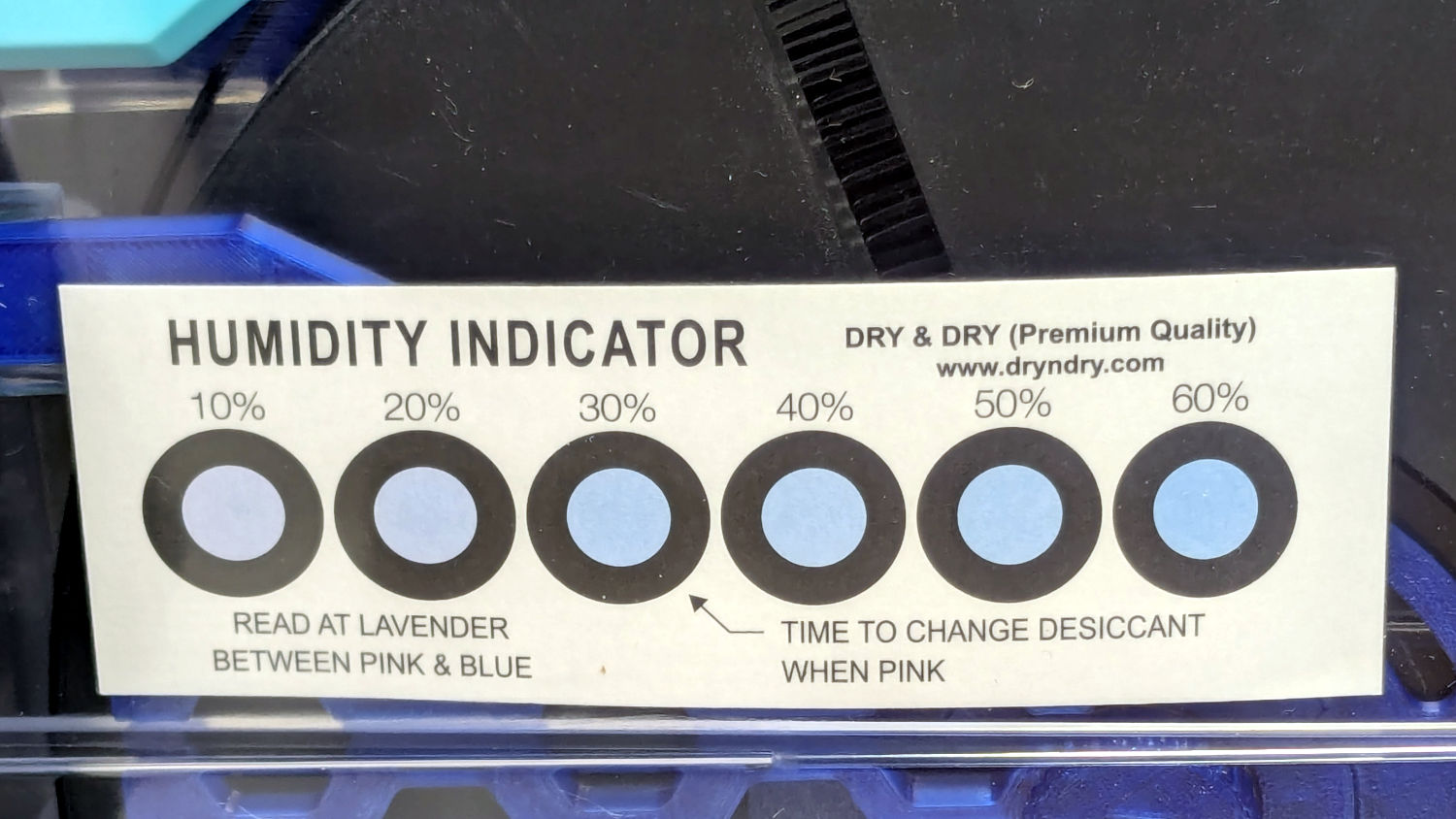
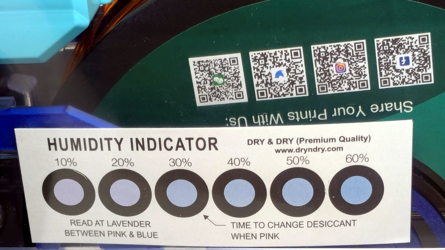
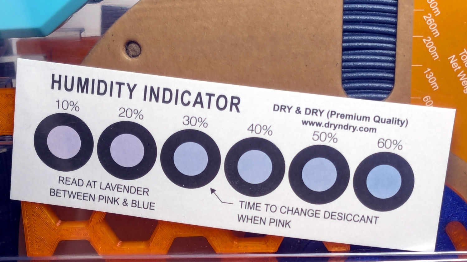
A week after installing 25 g of fresh silica gel, without any outside influence other than using some of the filaments to build things, I recorded the humidity meter reading, the indicator card colors, and the weight gain.
Click on any picture for more dots and to get rid of the captions and their stylin’ photo-blur.
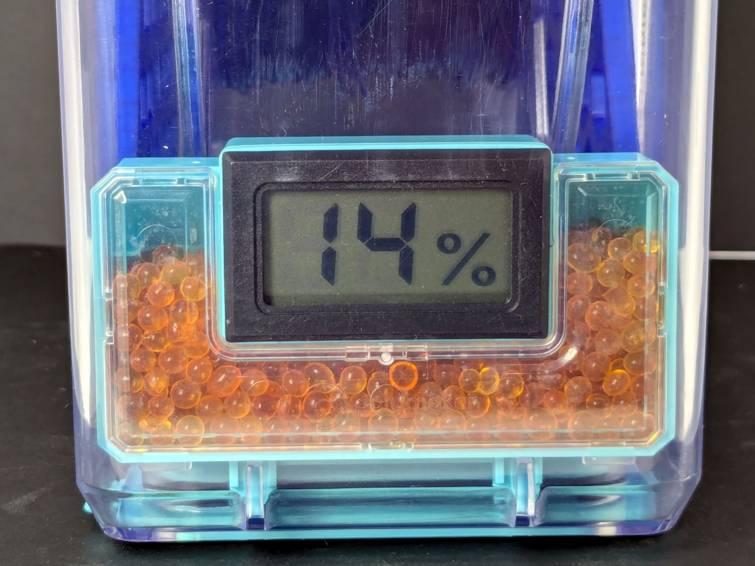
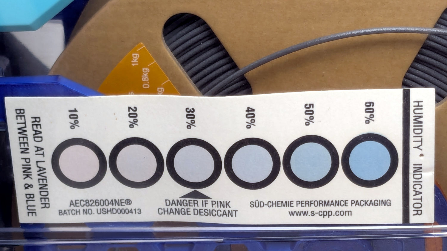
White PETG, gain 0.6 g:
Polydryer – 14 pctRH – meter – white PETGPolydryer – 14 pctRH – card – white PETG
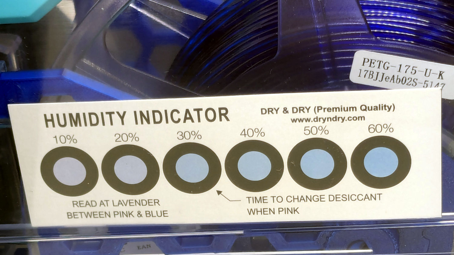
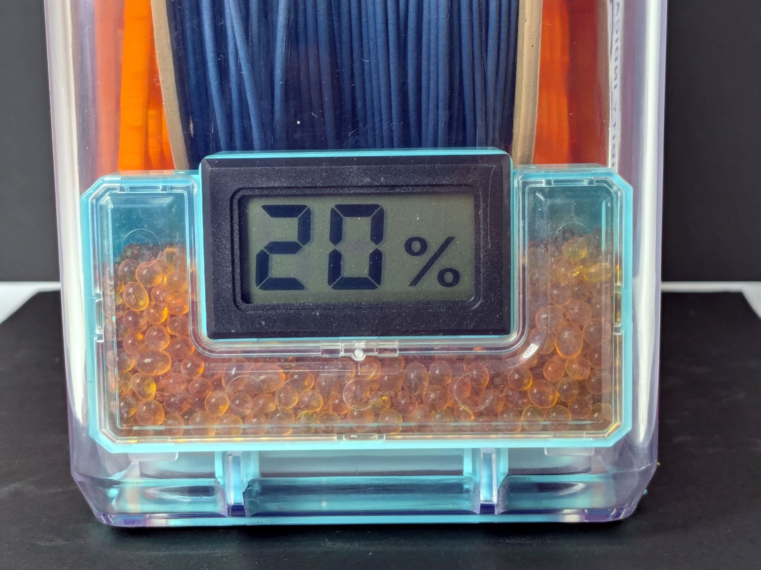
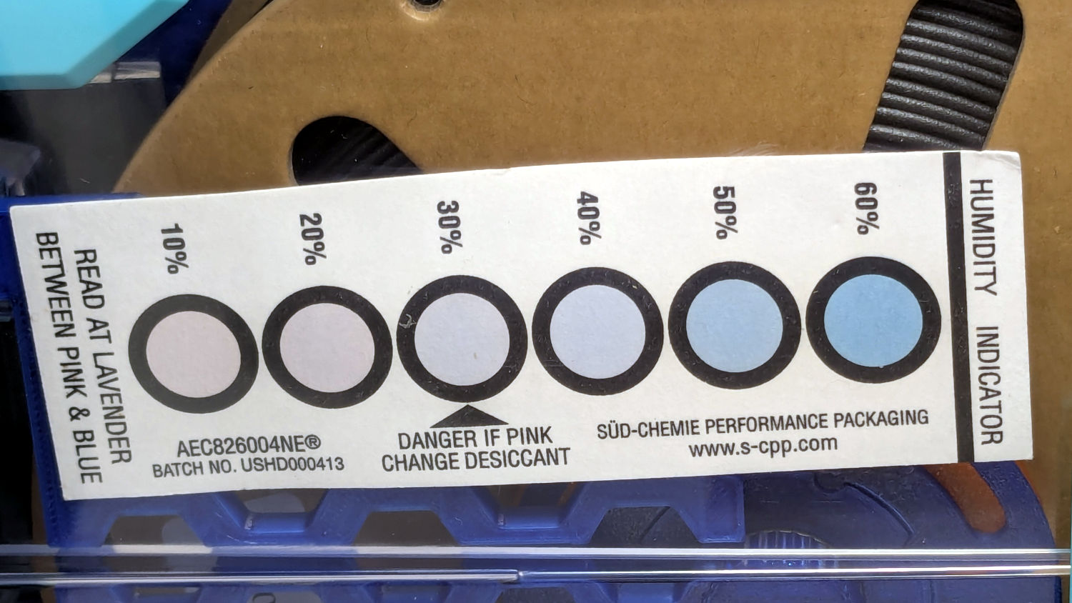
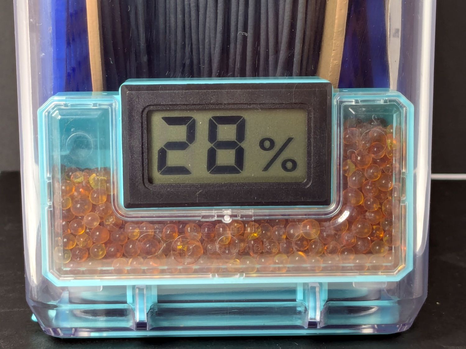
Black PETG, gain 0.8 g:
Polydryer – 21 pctRH – meter – black PETGPolydryer – 21 pctRH – card – black PETG
The (newer) indicator cards with the smaller dots / larger black borders seem less acute than the (older) large-dot cards. The two 28 %RH cards look about right, but the 20 and 21 %RH cards seem more different than the similar humidity would suggest.
Under 20 %RH, all the spots look pretty much the same, but AFAICT any humidity below 20 %RH is Good Enough for 3D printing.
The Blue PETG-CF went directly from its sealed bag into the PolyDryer box, unlike the Black and Gray PETG-CF spools that sat in the 50% RH basement long enough to soak up the ambience. The Blue has outgassed enough water to suggest spools do not arrive “bone dry” from the factory, although the Black and Gray prove the Basement Shop is wetter than the factory.
All of the silica gel together weighed 184.2 on the same scale I originally measured the 25 g quantities that should have totalled 175 g, but the individual measurements total 183.3 g. I don’t trust the scale to be better than ±0.1 g on any measurement, so half a percent is likely as good as it gets.
The silica gel weighed 187 g on the kitchen scale, sweated down to 179 g after 7 minutes in the microwave being defrosted like 1.5 pounds of fish, and, depending on which numbers you believe, released 8 to 10 g of water in the process.
Microwaving something containing so little water means the silica gel absorbs very little of the energy: the dish, glass turntable, and metal walls got absurdly hot. I think using the induction cooktop and cast iron pan makes more sense, even if it takes longer.
With fresh silica gel in place, perhaps waiting two weeks will produce interesting numbers.
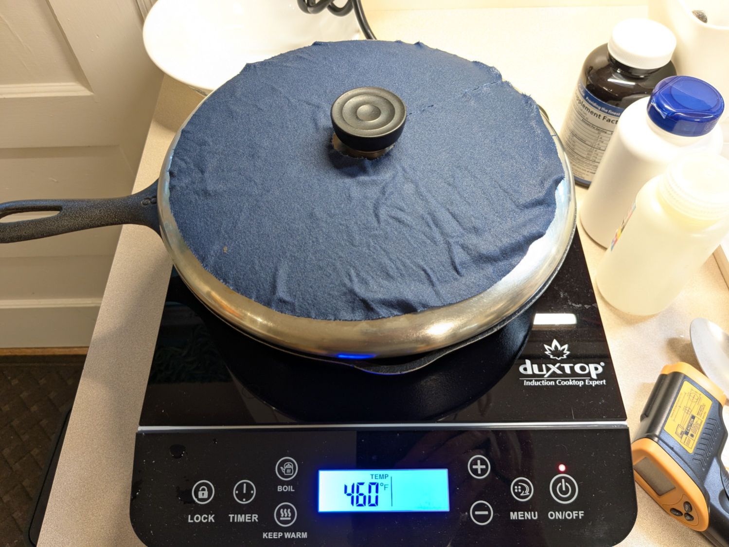
Having accumulated a bunch of used activated alumina desiccant, I figured now was a good time to try regenerating it. Industrial applications use dry gas and very high temperatures, but perhaps holding it over 100 °C for a few hours will suffice for my purposes.
After an hour the surface temperature was around 150 °F, so I covered the pan with a water-cooled lid to see if any vapor condensed on it:
Alumina regeneration – lid cooling
It did, indeed, so I alternated covering and exposing the pan, which was likely a waste of my time, until the alumina dried enough that the lid didn’t collect any condensation. The whole process took just under four hours with the cooktop set to its maximum of 460 °F for most of the time.
The beads then cooled to room temperature in a covered dish:
Alumina regeneration – final cooling
The beads weighed 626 g at the start of the adventure and sweated down to 593 g, parting with 33 g = 1.2 oz of water in the process for a loss of 5.6%. I have no idea how dry they are now, but they’re an ounce drier than before.
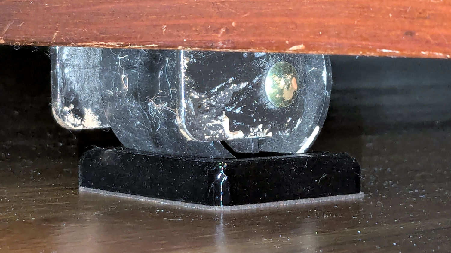
The upstairs Sewing Room came with a couch-like bed incorporating a roll-out trundle bed. It doesn’t get a lot of use, but it lacks wheel locks and tends to scoot away unless you get into it rather more carefully than seems reasonable.
So I made a pair of stops to capture the wheels:
Rolling Bed Stops – installed
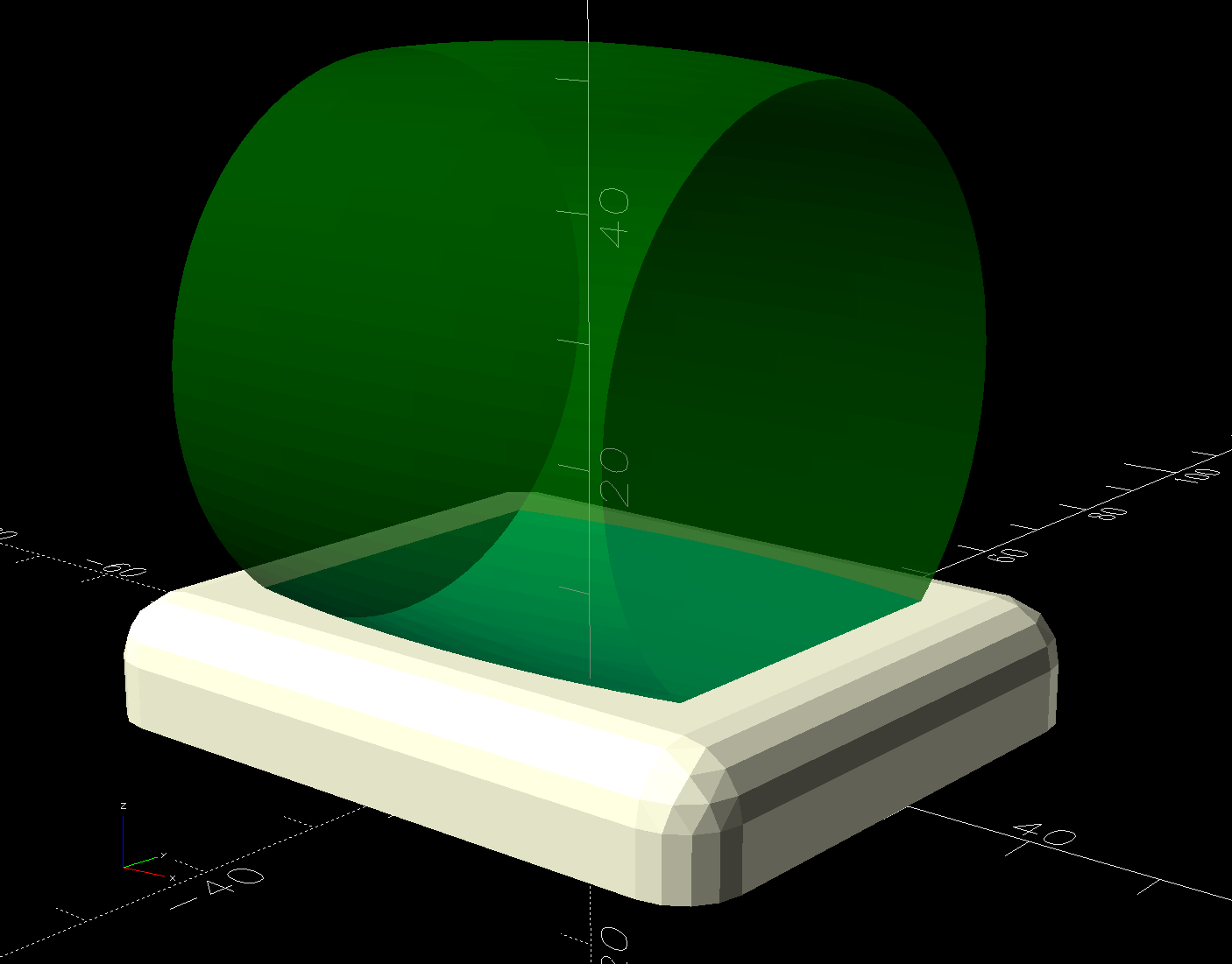
The solid model shows they’re just plastic blocks minus a model of the roller wheel:
Rolling Bed Stops – solid model – show view
I like the wood-grain effect of the doubly curved recess on printed plastic layers, even if nobody will ever see it:
Rolling Bed Stops – PrusaSlicer
The OpenSCAD code also exports a projection of the block as an SVG file to laser-cut the cork pad.
Roll the trundle bed into position, push the stops against the wheels, lift and pull forward an inch, let it down, and the wheels snap into those recesses.
These are considerably fancier than some of the other wheel stops / feet around the house, if only because I got to use the Chord Equation to solve for the radius of the circle parallel to the axle for a snug socket.
This file contains hidden or bidirectional Unicode text that may be interpreted or compiled differently than what appears below. To review, open the file in an editor that reveals hidden Unicode characters.
Learn more about bidirectional Unicode characters
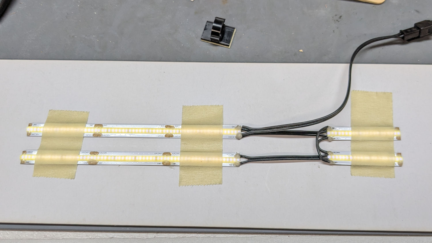
With the nose ring lights in place, I soldered up eight more 24 V LED strips to light the quilt under the HQ Sixteen’s arm:
HQ Sixteen – under-arm lights – bottom view
A simple fixture aligned the strips for soldering:
HQ Sixteen – under-arm lights – soldering fixture
I intended to peel the masking tape off the glossy cardboard, then use it to keep the strips aligned while I pressed the PSA adhesive on the back of the strips to the machine. The silicone molded over the LEDS turned out to be supremely un-stick-able to the tape and the strips got far more handling than I planned, but I think the adhesive will work.
The cable from the power supply now has a pair of JST SM connectors on the end. Although crimping two conductors into the same pin is not good practice, all 14 of the LED strips draw an aggregate of maybe 130 mA, so I think it’ll suffice.
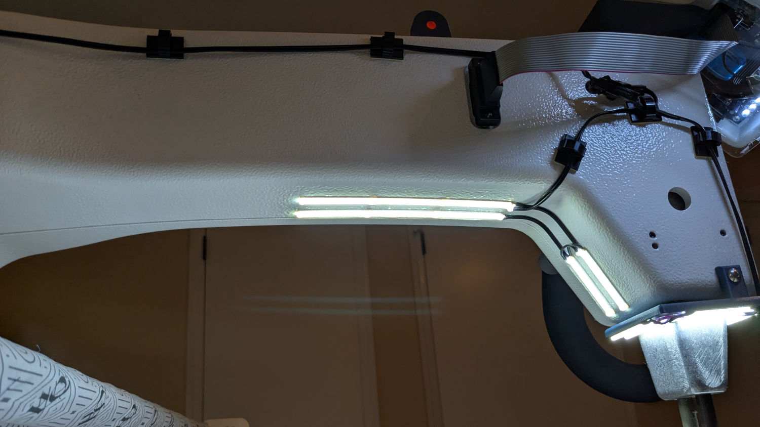
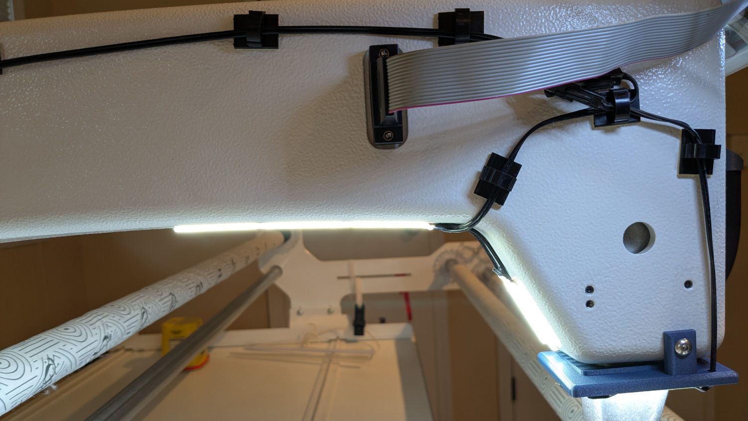
The JST connectors hide behind the ribbon cable going to the machine’s front panel, so there’s not a lot of basis for arguing they’re unsightly:
HQ Sixteen – under-arm lights – side view
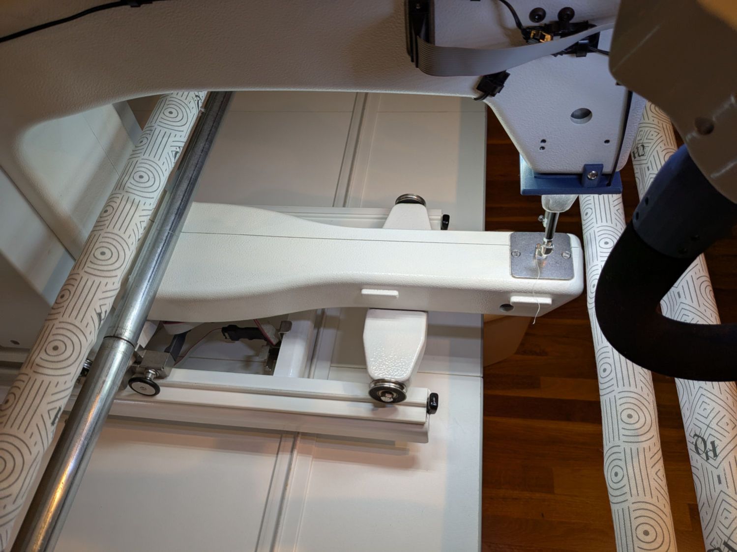
The finished part of the quilt passes under the bottom bar on the left (the rear of the machine table) and forms an ever-increasing roll around the top bar; the white fabric leader attaches to the edge of the quilt. The LED strips illuminate the in-progress part of the quilt under the arm and should be far enough forward to not snag on the rolled-up finished part.
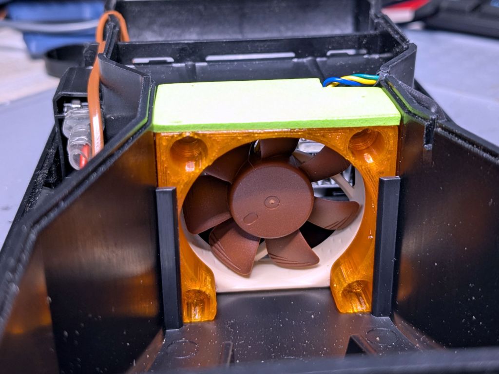
The OEM fan inside the PolyDryer is annoyingly loud, even to my deflicted hearing, so I printed a Noctua NF-A4x10 fan adapter and installed a much quieter fan:
PolyDryer – Noctua fan installed
The adapter is upside-down from the suggested orientation, I didn’t bother screwing it to the fan because it has sleeves fitting into the fan screw holes, the slot holds everything together, the vivid green EVA foam sheet sits atop a craft adhesive sheet (both cut with scissors!) ensuring they don’t part company, and it works just fine.
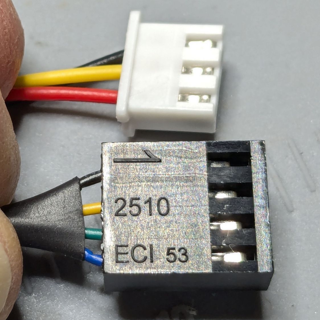
Of course, the OEM fan has a three-wire cable and the Noctua has a four-wire cable:
PolyDryer – OEM vs Noctua fan cables
Although you can’t quite make it out on the white plastic, both connectors have their Pin 1 marks adjacent to each other. I oriented them like that to put the pin release latches on top; a foolish consistency is the hobgoblin of small minds.
Fortunately, Noctua documents their pinout, a bit of probing verified the OEM fan pinout (which does not match the Noctua 3-wire pinout), and the Basement Warehouse Wing emitted an assortment of matching JST XHP connectors. Chop off the black connector and rewire it in a 3-pin XHP connector:
Pin 1 = OEM Red → Noctua Yellow = +24 V
Pin 2 = OEM Yellow → Noctua Green = Tachometer
Pin 3 = OEM Black → Noctua Black = Ground / Common
unused = Noctua Blue = PWM Speed Control
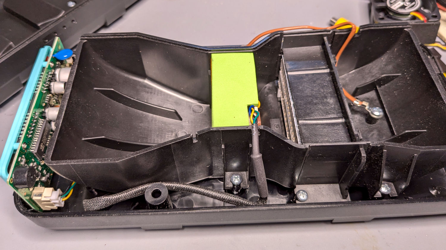
Which is barely visible plugged into the control PCB on the left:
PolyDryer – Noctua fan wiring
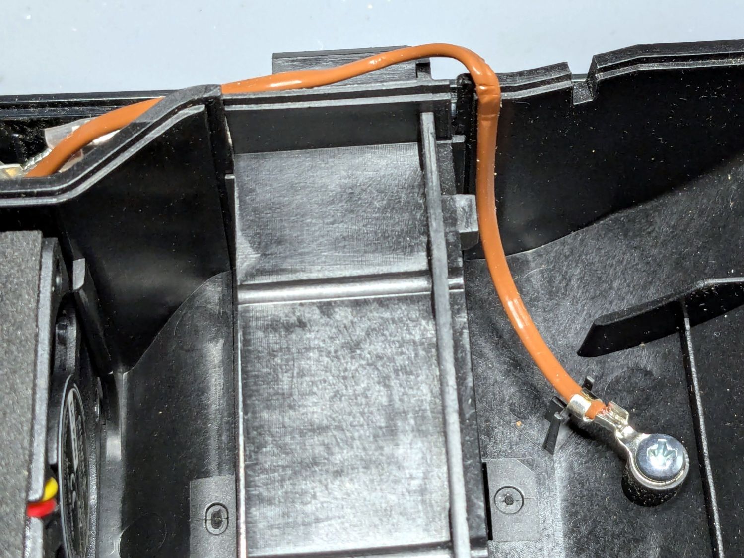
The brown thermocouple wire in the upper right didn’t start out in the notch intended to pass it out of the air flow downwind of the heater:
PolyDryer – crunched thermocouple wire
The wire is exceedingly stiff and requires some persuasion, but it will eventually stay in that slot.
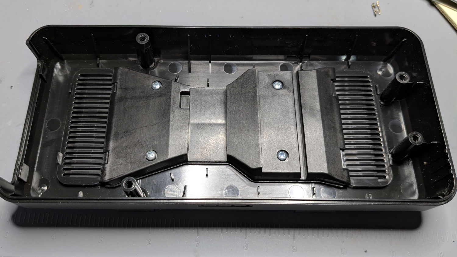
One of the PolyDryer modifications (which I can no longer find) suggested improving the vent openings, because the default slats block more than half of the surface area:
PolyDryer – molded vent slats
I chopped out all but three of the slats and stuffed an arch of aluminum window screen into each recess:
PolyDryer – vent screens installed
Admittedly, it looks a bit raggedy:
PolyDryer – vent screen – detail
As far as I can tell without actually measuring anything, the air flow has increased.
Now, to see how whether all that makes any difference.
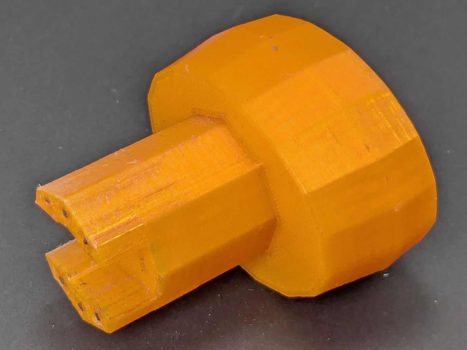
Mary found the wrench I made five years ago in the bottom of her tool bucket:
Hose Valve Knob – five years later
Having moved away from the garden with all the valves that wrench turned, it can now go into the 3D Printed Sample Box for use in the unlikely event I ever give another talk on the subject.
I’d design it differently these days, what with BOSL2 in my sails, but it got the job done.