Ed Nisley's Blog: Shop notes, electronics, firmware, machinery, 3D printing, laser cuttery, and curiosities. Contents: 100% human thinking, 0% AI slop.
Tag: Improvements
Making the world a better place, one piece at a time
A SquidWrench meeting discussion about printing transparent objects prompted me to conjure a soap dish from the vasty digital deep:
Shower Soap Dish – solid model
They’re all done in “natural” PETG with sufficient variations in speed, temperature, extrusion multiplier, and fill pattern to stock the shower & tub:
Translucent soap dishes
The single-thread sidewalls came out reasonably translucent in all the variations, but the baseplate remained stubbornly white-ish, even at 20 mm/s and 250 °C with 100% infill. The seams where the extruder retracts and lifts to the next layer remain conspicuous, with a scarf joint forming the white slab in the left-rear dish.
Quite a while ago, I’d considered making soap dishes with shattered-glass bottoms, but came to my senses. These have some key advantages:
Exactly the right size for narrow shower shelves
Light enough to not damage anything when it inevitably falls off
Reasonably unbreakable when that happens
Easily replaced
They’re also test pieces for the whole transparency thing, so it’s all good.
This file contains hidden or bidirectional Unicode text that may be interpreted or compiled differently than what appears below. To review, open the file in an editor that reveals hidden Unicode characters.
Learn more about bidirectional Unicode characters
The standard jaws for the Ortur Rotary loom over small-diameter workpieces:
Ortur Rotary Focus Pad – home offset adjustment
Some measuring and modeling produced petite 3D printed jaws:
Ortur Rotary – printed jaws
Admittedly, those jaws aren’t doing much of anything, but they’re not nearly as much in the way. You (well, I) can screw them in closer to the center to overlap the chuck jaws or another hole outward for slightly larger cylinders.
The solid model looks about the same:
Ortur Rotary Jaws – 2-3 show view
They build face-down with a little support under the screw recesses for a clean fit on the chuck:
Ortur Rotary Jaws – Prusaslicer
Teeny jaws might be handy:
Ortur Rotary Jaws – 2-2 show view
Screwing them in one hole outward lets them grip medium cylinders without sticking out from the chuck jaws:
Ortur Rotary – small printed jaws
The OpenSCAD code lets you pick which screw holes you want, but it does not error-check the perverse choices.
This file contains hidden or bidirectional Unicode text that may be interpreted or compiled differently than what appears below. To review, open the file in an editor that reveals hidden Unicode characters.
Learn more about bidirectional Unicode characters
Ruida laser controllers do not allow the platform to rise above the U=0 origin set by the autofocus pen = switch. While this isn’t a problem for flat surfaces, focusing on the exact top of a horizontal cylinder, particularly a small rod, may be overly difficult.
So a focusing pad seems like a Good Idea™:
Ortur Rotary Focus Pad – focus pen positioning
The general idea:
Align a flat horizontal surface with the rotary chuck’s axis
Do the autofocus operation with a well-defined landing zone under the pen
Jogging the head upward (= platform downward) by the workpiece radius puts the focused spot exactly at the right height
Remove the focus pad
Install the workpiece
Fire The Laser
The solid model:
Ortur Rotary Focus Pad – solid model
Features of note:
The chuck jaws fit into the recesses on the left end for a firm grip with good alignment
The lengthwise notch lies on the rotary axis parallel to the laser’s X axis
The crosswise notch is juuust rightward of the chuck jaws, marking the leftmost end of whatever you’re engraving
Because I added a home switch to the Ortur YRC-1 case, Jaw 1 automagically ends up on top after homing, thus automagically making the focus pad horizontal. Getting that right required fine-tuning the rotary’s home switch trip point, which turned out to be easier to do using the Home Offset configuration value after I replaced the cam I thought would work:
Ortur Chuck Rotary home switch – pulley cam
Instead, a simple M4 setscrew (standing proud of the pulley surface in one of the tapped holes for the real setscrew securing the pulley to the shaft) trips the switch much more repeatably :
Ortur Rotary Focus Pad – home trip setscrew
The setscrew on the right sits flush with the surface to prevent the switch roller from falling into the hole. The real setscrew underneath it locks the pulley to the shaft’s flat.
With that in place, a quick binary search settled on a Y axis Home Offset = 1.75 mm to put the pad level with the top of the rotary’s case, which is Level Enough™ due to my tweaking the machine’s foot elevations after jacking the whole machine up on risers:
Ortur Rotary Focus Pad – home offset adjustment
The Home Offset value:
The speed and acceleration values are much lower than used with the linear Y axis, because apparently Ruida computes the corresponding step values using the workpiece diameter in the Rotary section. Small diameters produce impossibly fast motions, which suggests they expect you to set the optimum values based on back-calculations from the object diameter; ain’t nobody got time for that.
Anyhow.
After autofocusing, the red-dot pointer now indicates the laser spot position, so jog the X axis and drag the gantry to put the spot on the axis mark:
Then jog the X axis to put the dot at the transverse mark just beyond the chuck jaws:
Ortur Rotary Focus Pad – red dot at origin
Hit the Ruida Origin button to set that as the user origin, so you can reference the LightBurn design to the hardware position.
Move the platform down by the workpiece radius, jog the nozzle along the X axis to get it out of the way, remove the focus pad, install the workpiece, and you’re good to go. The checklist visible beyond the bubble level shows it’s not quite that simple, but we’re getting there.
This file contains hidden or bidirectional Unicode text that may be interpreted or compiled differently than what appears below. To review, open the file in an editor that reveals hidden Unicode characters.
Learn more about bidirectional Unicode characters
I used to think there was some correlation between the indicated humidity and the amount of water adsorbed by the silica gel, with the humidity rising as the gel absorbed more water. That is obviously not the case.
Instead of the adsorption being a function of the equilibrium humidity, it’s the other way around. With the humidity held constant (by adding water vapor), the silica gel will adsorb thus-and-so percentage of its weight and equilibrate at that humidity. If the filament was an infinite reservoir of dampness, then the equilibrium humidity would indicate how much the silica gel had coped with.
At least I think that’s how it goes. I have been wrong before.
Anyhow, IMO the right way to proceed is to just replace the silica gel every month and be done with it.
Also true: the humidity meters aren’t particularly accurate at the low humidity values in those boxes.
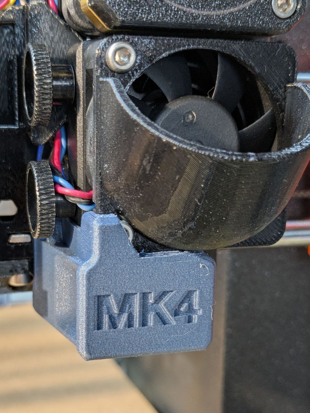
I’d stuck four exercise mat tabs (scraps of a flooring project) under the feet, but the loading was much too high:
Prusa MK4 Foam Feet – foam snippets
It was really an excuse for some non-critical cutting with the 3 inch lens in the laser cutter:
Prusa MK4 Foam Feet – assembled
The foam cut nicely, albeit with a 1.3 mm kerf, and the chipboard & plywood seemed about the same. They’re 30 mm square and, should they flatten out, I have enough foam scraps for a larger set.
Unlike the 3018 feet, my deflicted ears can’t tell the difference with these in place, so I assume a standard MK4 squash-ball foot upgrade isn’t worth the filament.
The manual accompanying my OMTech 60 W CO₂ laser clearly states it has a 1.5 inch focus lens:
OMTech laser packing list – 1.5 inch focus lens
Which I had always assumed was the case, even though a short lens like that would typically be used for fine engraving due to its smaller spot size. One could argue the carton should have included a 1.5 inch lens in addition to whatever was in “its optics”, but it didn’t.
It has a 2 inch lens, as I confirmed while switching to a 3 inch lens to get more clearance over the Ortur rotary than the stock lens allows:
Ortur Chuck Rotary – 2 inch focus lens
The bottom of the lens (its planar surface) sits inside the nozzle at (about) the same level as the joint just above the assist air fitting:
OMTech laser – 3 inch lens focus distance
That’s the proper focus distance for the 3 inch lens, with the lens 3 inch = 3 × 25.4 = 76.2 mm above the platform. There’s obviously some room for quibbling about the optical center of the lens vs. the lower surface and so forth and so on, but a ramp test shows it’s Close Enough™:
Ramp Test – 3inch lens – 2025-12-29
Which adds an inch of clearance, enough to prevent obvious collisions:
Ortur Chuck Rotary – 3 inch focus lens
Changing the lens requires removing the air fitting, during which operation I also moved the clamp holding the focus pen. Because that changed where the switch trips, the Focus Distance also changed:
2 inch lens = 12.7 mm
3 inch lens = 12.7 + 25.4 = 38.1 mm
The clearance under the nozzle depends only on the lens:
2 inch lens = 18.5 mm
3 inch lens = 18.5 + 25.4 = 43.9
I’ve been using step gauges for manual focusing with the 2 inch lens:
OMTech focus pen – tripped vs nozzle
I figured a rod would be more appropriate for the 3 inch lens and, hey, now that I have a rotary, I can engrave it:
OMTech laser – 3 inch lens focus stick
Through no fault of mine at the lathe, that stick is exactly 43.9 mm long, but “44 mm” fit better.
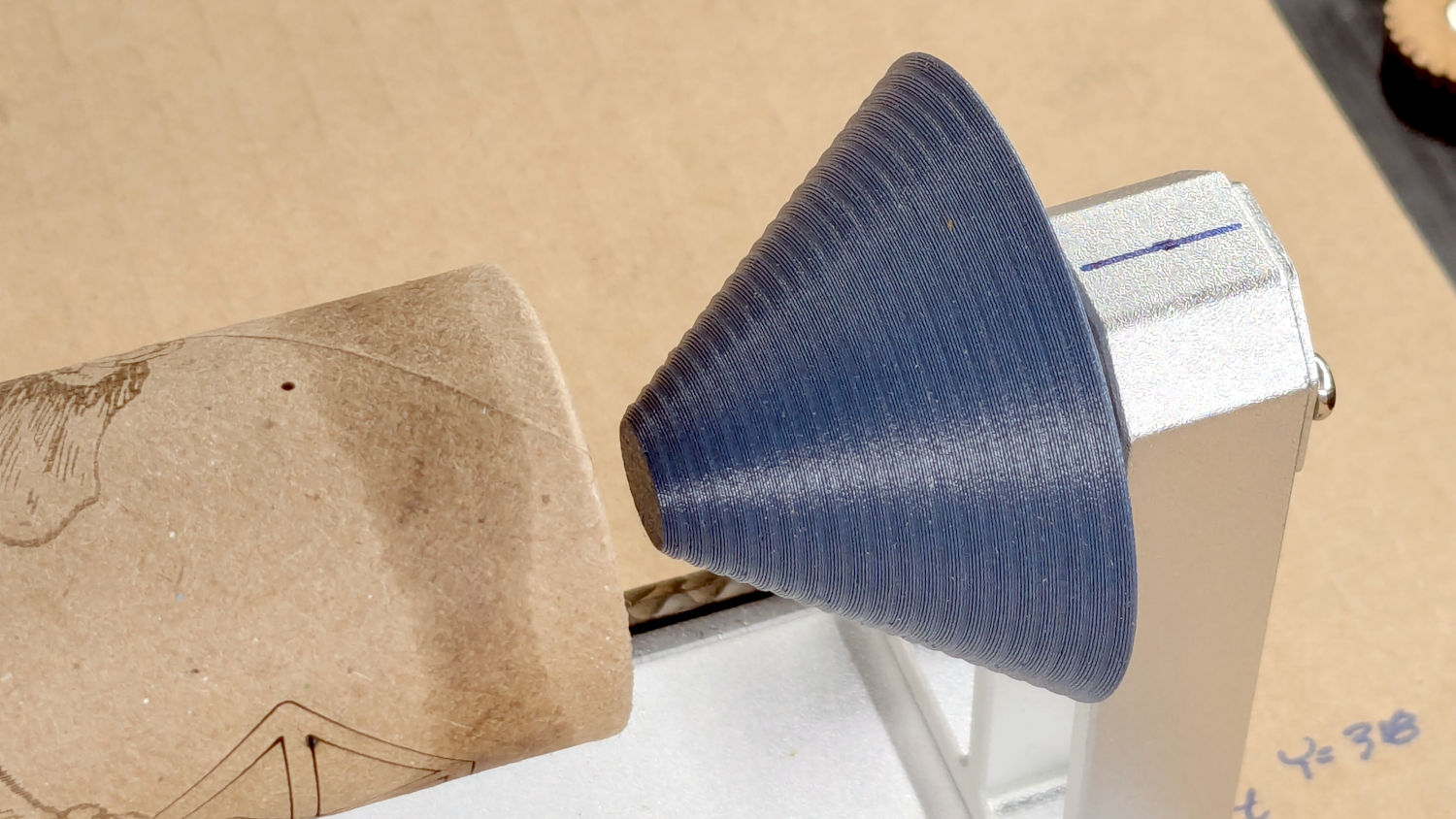
A conical (a.k.a. bullnose) center in the tailstock simplifies supporting cylindrical objects:
Ortur Chuck Rotary conical center – installed
The spring-loaded tailstock bearing has a 5 mm bore. The bullnose rests against a small spacer on its 5 mm shaft to hold it away from the bearing’s mounting screws with some bearing spring compression. I turned the spacer from aluminum rod because lathe work is satisfying, but a printed spacer would work fine.
The bullnose is a cone with steps encouraging the cylinder to sit properly:
Ortur Rotary Conical Center – 10-50mm
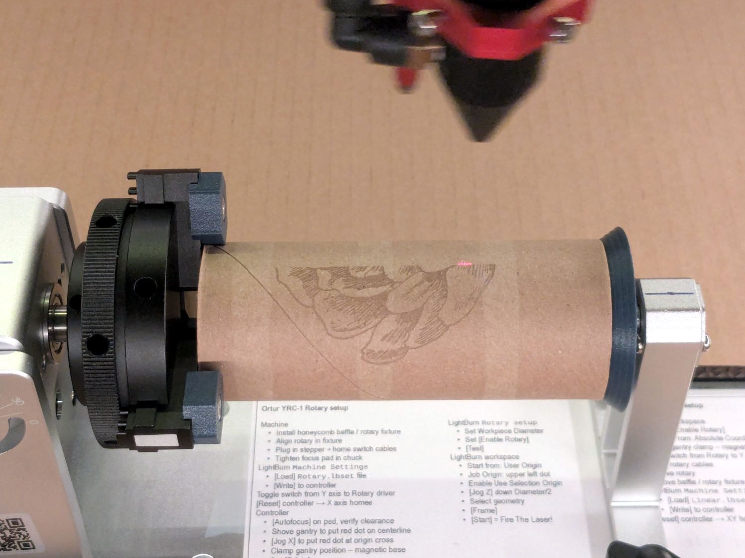
With both ends centered, the cylinder sits concentric with the chuck axis:
Ortur Chuck Rotary home switch – jaw position
The chuck grabs the OD and the bullnose supports the ID, so removing crud from both ends is in order.
The bullnose won’t work for a solid rod, so a negative cone = cup center may come in handy:
Ortur Chuck Rotary cup center – installed
Stipulated: A CO₂ laser will bounce right off a solid aluminum rod. Imagine I chucked up a wood dowel, OK?
A cup center is what remains afteryoinking a bullnose out of a cylinder:
Ortur Rotary Conical Centers – cup
Looks like I did exactly that:
Ortur Chuck Rotary conical centers
Somewhat surprisingly, the two parts nest perfectly:
Ortur Chuck Rotary conical centers – nested
That’s without the shaft installed on the cup, so they won’t sit quite so neatly on the shelf.
Aligning the rotary axis along the laser’s X axis and setting the focus requires attention to detail, but a decent tailstock center makes that effort meaningful.
This file contains hidden or bidirectional Unicode text that may be interpreted or compiled differently than what appears below. To review, open the file in an editor that reveals hidden Unicode characters.
Learn more about bidirectional Unicode characters